CDL Offset Pivot Installation Instruction
Open the original PDF document
View PDFInstallation Instructions Concealed Door Loop (CDL) for 3/4" Offset Pivot Application Only

Purpose:
The CDL-EXT is used to provide a concealed transfer of power from the door frame to the door for 3/4" offset pivot applications ( NOT for center hung or 1-1/2" offset pivots). This product has a limited swing range of up to 105º .

DO NOT PROCEED WITHOUT READING THIS SECTION OF THE INSTRUCTIONS.

To determine the best location for installation, please take the following into consideration:
- 1. Be sure that the opening does not exceed 105º swing range.
- 2. Fixed side of the CDL MUST be attached to the door and the active side of the CDL MUST be attached to the frame. DO NOT ADJUST CENTER STOP ON CDL .
- 3. When door is closed the total length of the CDL (12") will be concealed inside the door frame, so be sure to allow enough room for total concealment.
- 4. Be sure to select a location on the door for the CDL that does not compromise the structural integrity of the door when drilling the 5/8" hole.
- 5. Be sure to select a location on the frame for the CDL that will not come into contact with any reinforcement or anchoring brackets within the frame when drilling the 5/8" hole.
- 6. The height the CDL is mounted is not critical, but commonly are installed at least 30" off the floor. For best results, position the CDL in a location that allows the loop to travel down the inside of the door frame and provides proper wire slack for free movement. (see fig. 4)
- 7. The wire cable MUST slide freely within the CDL's armored cable. Installing a cable that is too thick to slide freely will result in premature failure due to flexing and stretching.
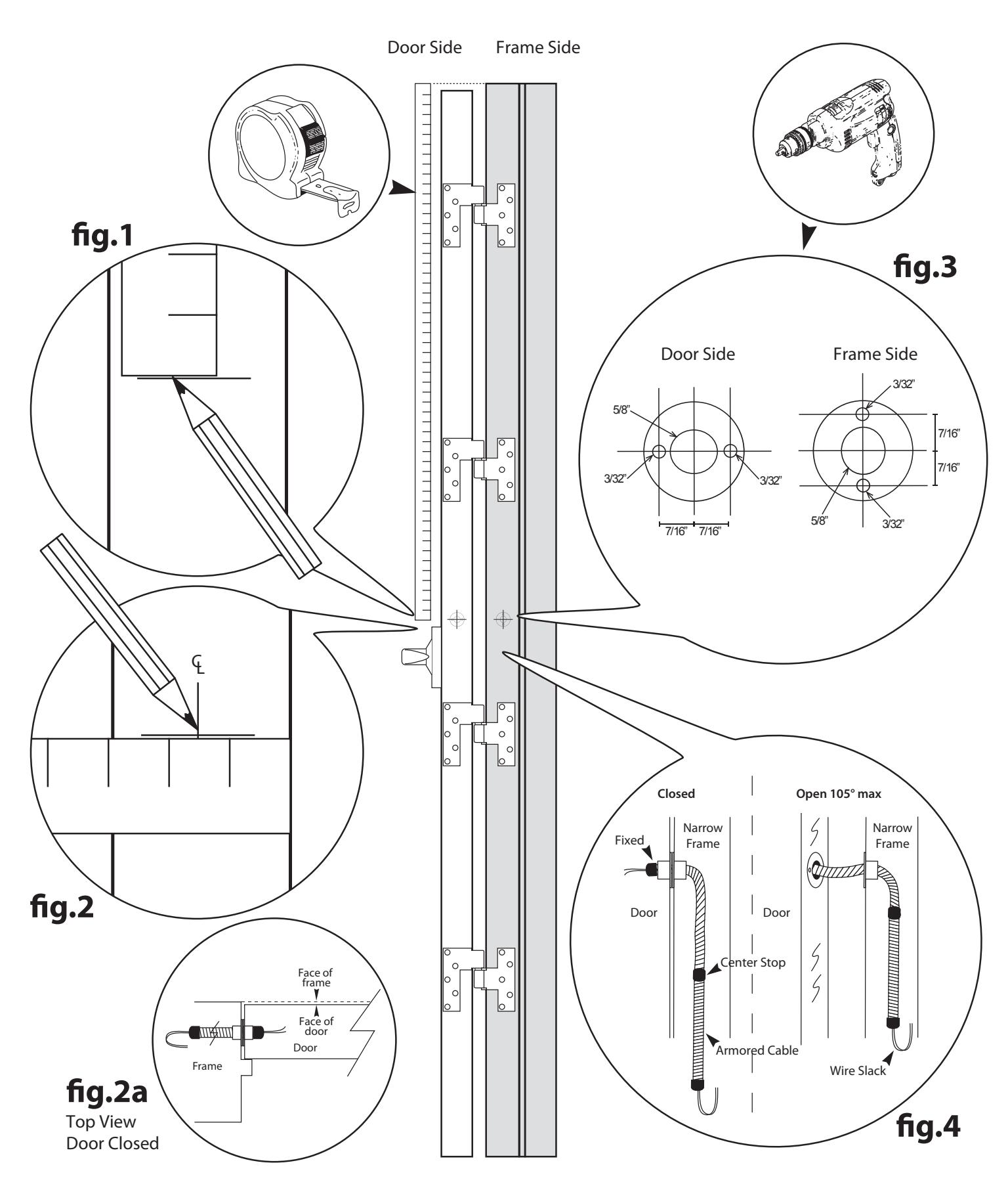
THE FOLLOWING STEPS GO ALONG WITH THE DIAGRAM ON PAGE 2
Preparation of door & frame:
- fig.1- With the door partially open, measure and mark the distance from the frame header to the desired location on the frame. Using the same measurement, mark the distance from the frame header to the desired location on the door. This will be your vertical location.
- fig. 2- Measure and mark to the center of the door for your horizontal location (this makes the center point for your door prep). Take the center door measurement and mark the frame accordingly. If pull side of the door is not flush with the face of the frame, be sure to add any difference from the face of frame to face of door, if any, when marking the reference point on your frame. (see fig. 2a)
- fig. 3- Drill a 5/8" hole in both the door and frame sides for the CDL to slip into. For the CDL to conceal properly, there must be 12" of room inside the frame for the CDL armored cable to move freely. (see fig. 4) Insert one end of the CDL in the door and mark the screw holes at the 3 and 9 o'clock positions. Insert one end of the CDL in the frame and mark the screw holes at the 6 and 12 o'clock positions. Use a #43 (approx 3/32") drill bit and pilot out all four screw holes.
Installation:
fig. 4- Insert the wire through the CDL and make any required wire terminations. Install the door side of the CDL using the proper type of screws provided (leave appropriate slack). Install the frame side of the CDL using the proper type of screws provided (leave appropriate slack). Carefully open & close the door to verify proper alignment and function of the CDL. The armored cable should move freely through the frame side CDL end piece.
For Continuous and Butt Hinge installation, see CDL for Continuous and Butt Hinge Installation Instructions.
Command Access Technologies | 22901 La Palma Ave. Yorba Linda, CA 92887 | Phone: (888) 6-ACCESS Fax: (888) 622-2302
DIAGRAM FOR VISUAL REFERENCE ONLY - NOT DRAWN TO SCALE
For Continuous and Butt Hinge installation, see CDL for Continuous and Butt Hinge Installation Instructions.
Command Access Technologies | 22901 La Palma Ave. Yorba Linda, CA 92887 | Phone: (888) 6-ACCESS Fax: (888) 622-2302