CAT AIR REX Installation Instruction
Open the original PDF document
View PDF

CAT-AIR
I N S E R T I n s t r u c t i o n s
The Command Access CAT-AIR is a field-installable Request to Exit Sensor with Active Infrared Detection (AIR) that focuses directly in front of the door handle.
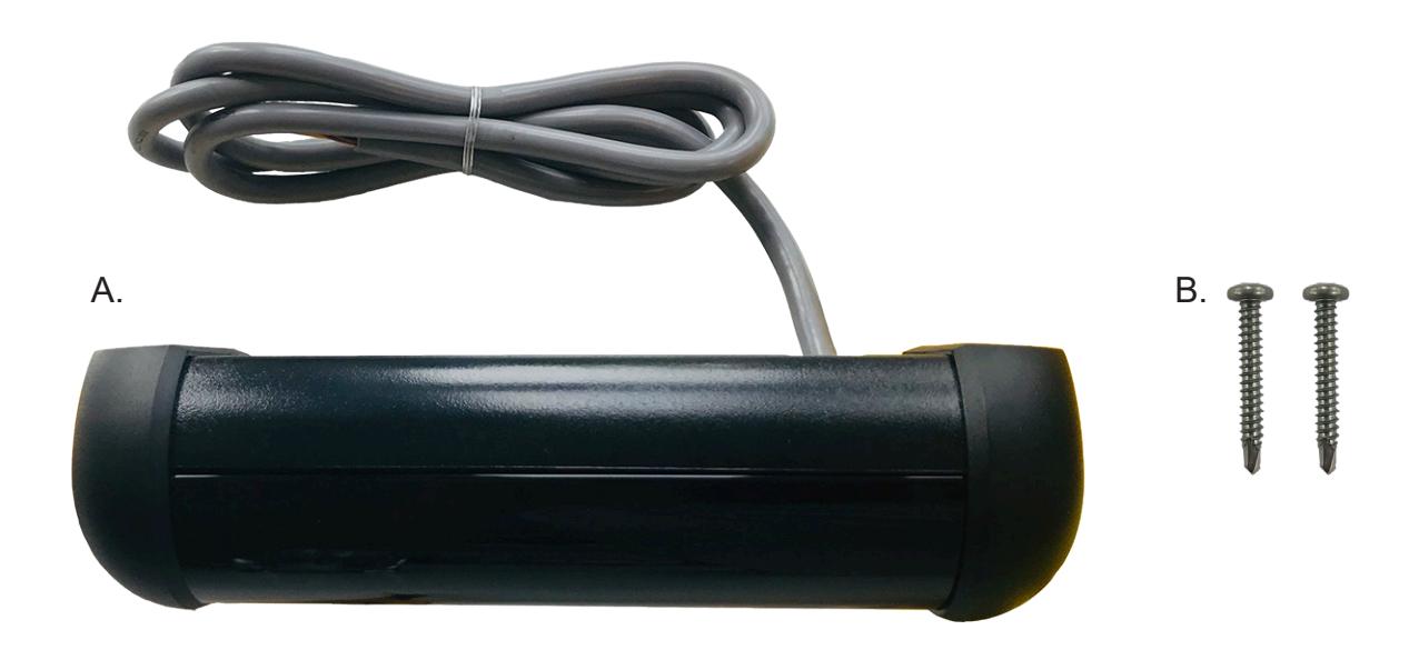
INCLUDED IN KIT
- CAT-AIR sensor A.
- Self-tapping screws (x2) B.
Features
- Low profile sensor mounts on or above the door frame
- Multiple re-locking modes for timed or door position conditions
- Relay consists of two Form "C" contacts for NO/NC wiring
- Three dry auxiliary inputs: request to exit, card reader and push button
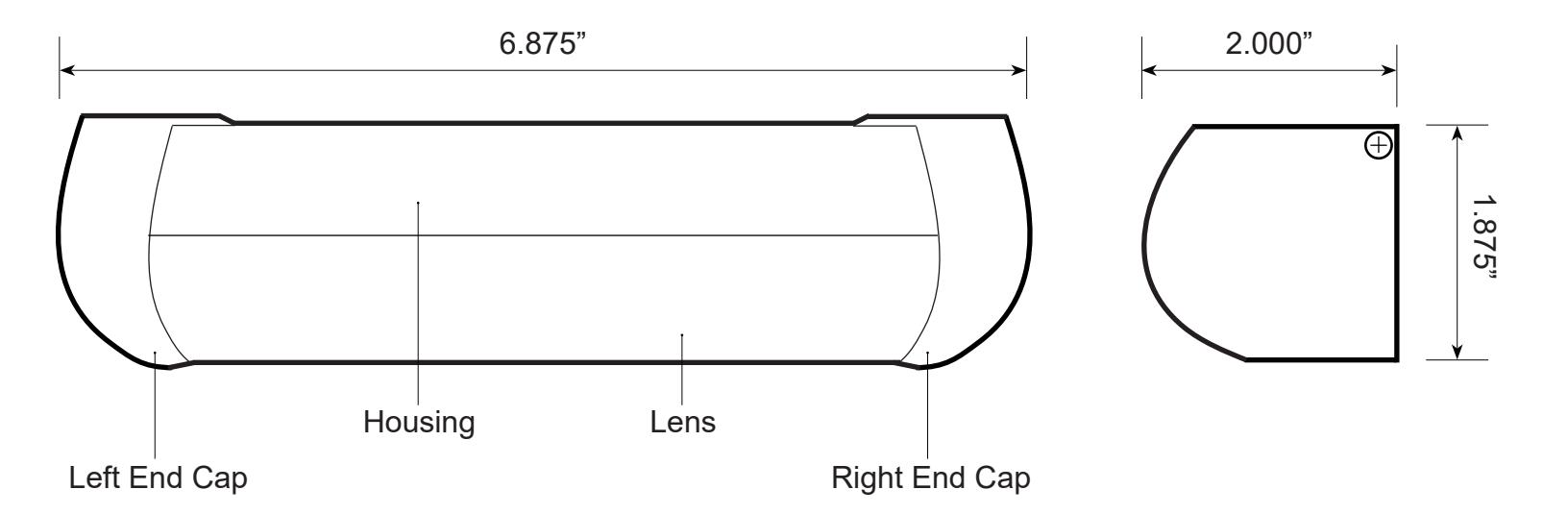
- Adjustable tilt angle from 0 10 degrees
- Adjustable detection range from 20 48 inches
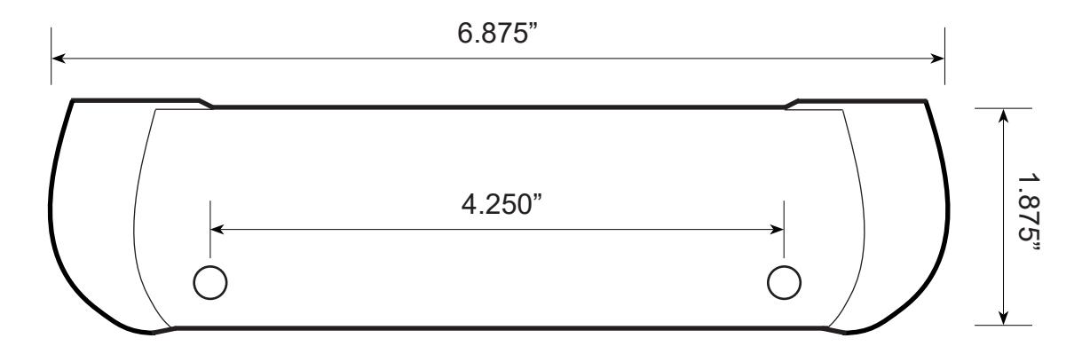
dimensions and specifications

specifications
• Detector Type: • Supply Voltage: Focused Active Infrared 12 - 24 VAC/VDC - 60 Hz
• Current: Sounder OFF: 155mA - Sounder MAX Volume: 200mA
• Detection Range: 20 - 48 inches, adjustable
• Relay: 2 form "C" contact sets; 1.3A - 24VAC / 30VDC
• Relay Hold Time: • Sounder: 0.5 - 60 seconds, adjustable 85 dB max, adjustable
• Indicator LEDs: • Wiring Interface: Green, Red, Yellow and Orange JST (14-pin) with 4 foot cable
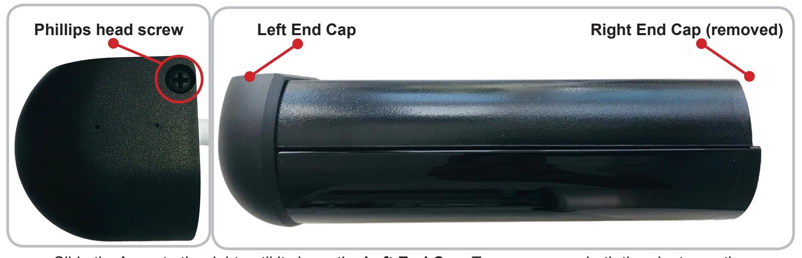
INSTALLATION

Remove the Phillips head screw on the right side of the sensor to slide off the Right End Cap .
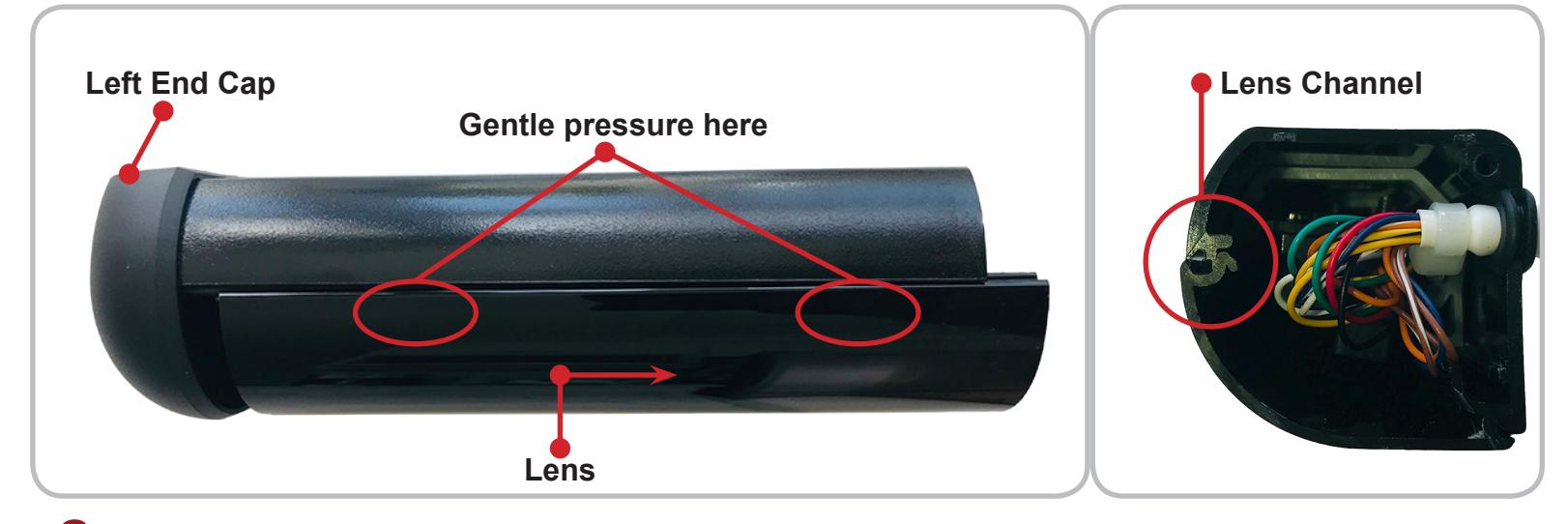
Slide the Lens to the right until it clears the Left End Cap . To remove, use both thumbs to gently press down on the top the Lens , near the Housing , in order to clear its Channel . Then gently pull forward and away from the Housing .
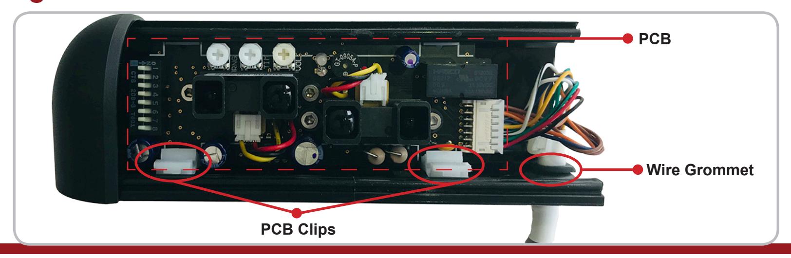
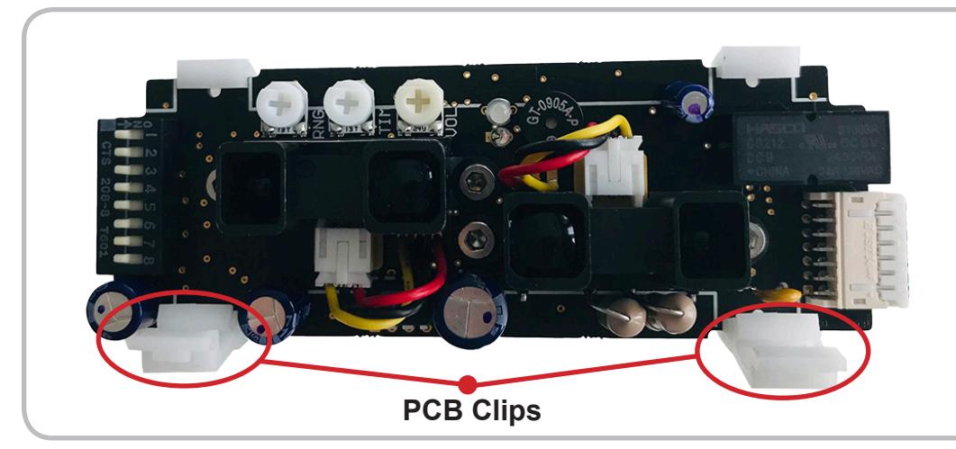
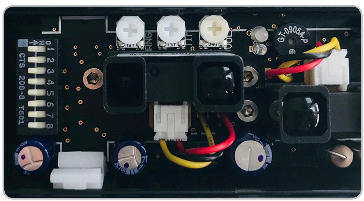
With the Lens removed, identify the PCB (printed circuit board), its Two Clips and the Wire Grommet .
installation

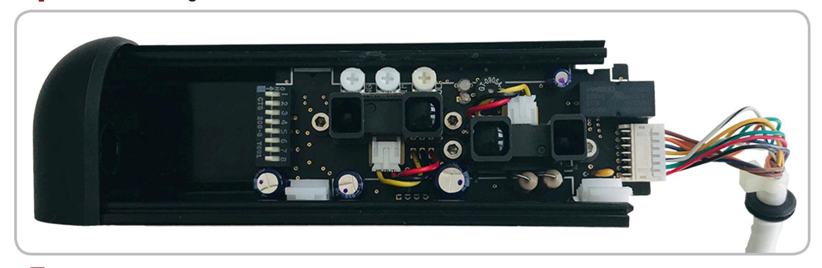
4 Gently pull the Wire Grommet to the right and out of the Housing . Next, slide the PCB to the right and out of the Housing as well.
5 The Housing has two pre-drilled Mounting Holes you will loose when installing the sensor.
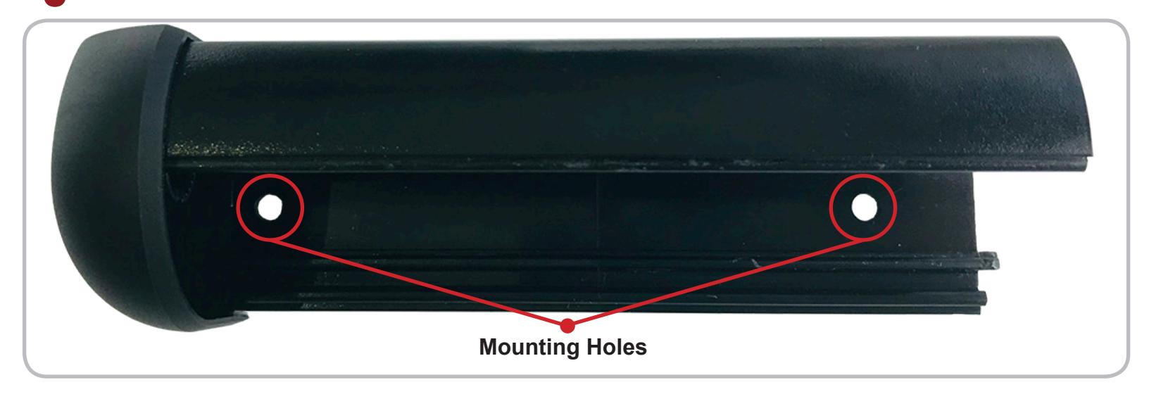
*Use an 1/8" bit if drilling pilot holes.
installation

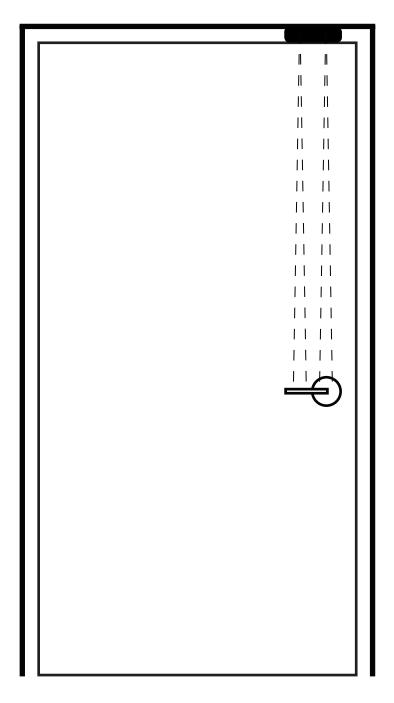
The active infrared sensor (AIR) is made up of two narrow, side-by-side detection zones that project at slightly offset angles. Centering the Housing directly above the door handle helps create the ideal detection zones that cover the full width of the handle.
6 For best performance, mount the Housing so it is centered directly above the door handle using the two provided self-tapping screws.
*If cabling needs to pass directly into the header, drill a 3/8" hole next to the sensor's right end cap where the wire grommet is located.
- 7 Once the Housing is mounted in its desired location, re-install the PCB , Lens and Right End Cap by reversing Steps 1-4.
- 8 Once the sensor is installed, the final wiring can be completed use its 4' cable and 14-pin connector.
| Wire Color | Signal | Wire Color | Signal |
|---|---|---|---|
| Red | 12 to 24 VAC / DC +/- 10% | Black | 12 to 24 VAC / DC +/- 10% |
| White/Black Stripe | Relay 1 Common | Blue | DRY Card Reader Input |
| Green/Black Stripe | Relay 1 Normally Open | Blue/White Stripe | DRY Card Reader Input |
| Yellow/Black Stripe | Relay 1 Normally Closed | Orange | DRY REX Input |
| White | Relay 2 Common | Orange/White Stripe | DRY REX Input |
| Green | Relay 2 Normally Open | Brown | DRY Door Position Switch Input |
| Yellow | Relay 2 Normally Closed | Brown/White Stripe | DRY Door Position Switch Input |
SENSOR ADJUSTMENT

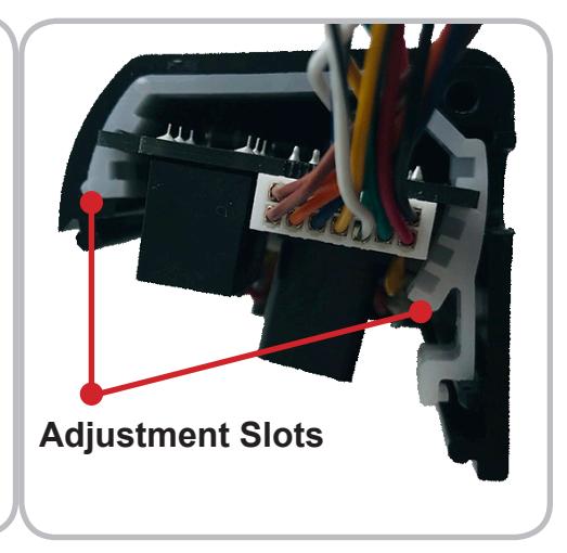
Aside from the placement of the housing, the only mechanical adjustment remaining is the sensor's angle. The sensor is factory pre-set to the 5 degree position but may be reduced to 0 degrees or increased to 10 degrees. The greater the angle, the farther from the door handle the detection zones will be. For most applications, it is recommended that the unit be powered on and tested at the factory pre-set 5 degrees.
The ideal position of the detection zones is directly in font of, but not touching the door handle. This will allow the sensor to read when someone grasps the handle but will also be close enough so that the sensor isn't engaged by someone walking past the door. After testing, if the detection fields needs to be changed, adjust the angle setting as shown below.
*After powering on, if the sensor is always activated or detecting erratically, there is a good possibility that the sensor's detection zones are reflecting off of the door handle and should be adjusted outward.
With the PCB and its Clips removed from the housing, gently press down on the front of the Clips and push them off the PCB. Then slide the PCB into different Slots of the Clips to adjust as needed.
-
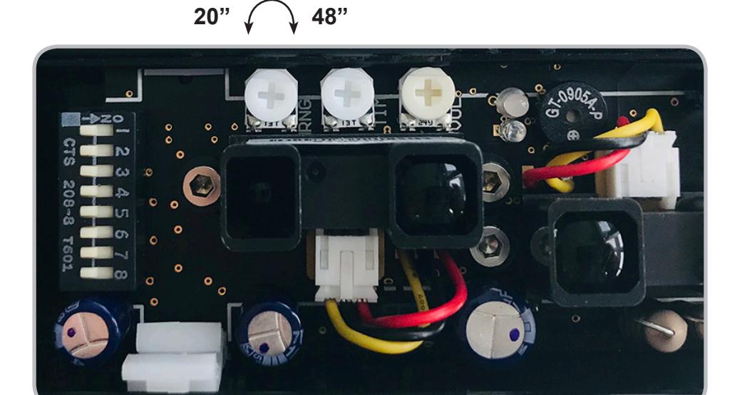
The detection distance (range) is adjusted using the Single-Turn "RNG" Potentiometer.
- To decrease the detection distance, turn the potentiometer counterclockwise. Minimum distance = 20"
- To increase the detection distance, turn the potentiometer clockwise. Maximum distance = 48"
SENSOR ADJUSTMENT

-
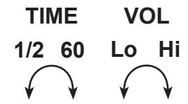
The relay hold time is adjusted using the
Single-Turn "TIME" Potentiometer
. The potentiometer will we be non-linear, with the 1/2 10 second adjustment covered by the first half-turn and the 11 60 second adjustment covered by the second half-turn.
- To decrease the hold time, turn the potentiometer counterclockwise. Minimum hold time = 1/2 second
- To increase the hold time, turn the potentiometer clockwise. Maximum hold time = 60 seconds
-
1 The alarm volume is adjusted using the Single-Turn "VOL" Potentiometer.
- To decrease the hold time, turn the potentiometer counterclockwise. Minimum hold time = 1/2 second
- To increase the hold time, turn the potentiometer clockwise. Maximum hold time = 60 seconds
INDICATOR LED
Green On/Running and no detection.
Red Object in detection or input activated. (example: hand in detection or REX asserted)
Yellow Relay active by relay hold time. (re-lock mode set to timer mode as selected by DIP 2)
Flashing Orange When the sensor or any of the enabled inputs are in constant detection for greater than
10 seconds successively. As soon as the sensor is no longer in detection, it will resume
normal opertaion.
dip switch adjustment

13
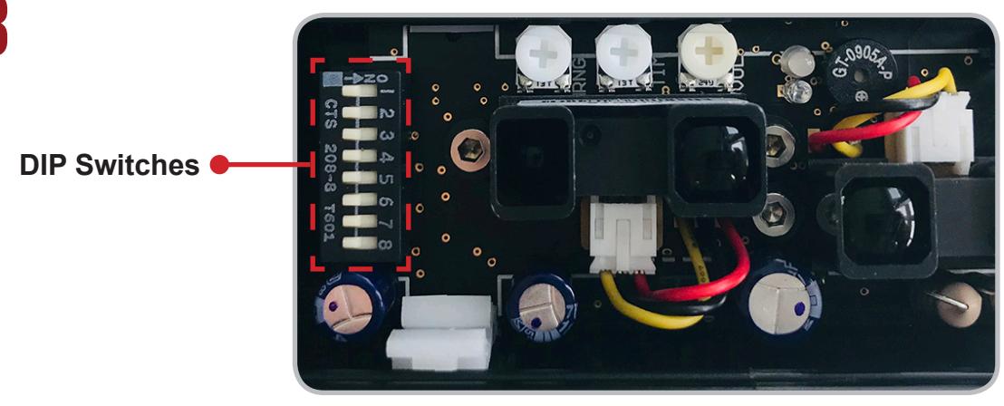
| DIP 1 | The sensor will enter either Fail-Safe (ON) or Fail-Secure (OFF) if stuck in constant detection. | ||
|---|---|---|---|
| DIP 2 | Re-lock mode is door position (ON) or timer mode (OFF).* | ||
| DIP 3 | Door position mode advanced re-lock time is 10 seconds (ON) or 30 seconds (OFF).* | ||
| DIP 4 | Relay hold-time restart (ON) or continue down (OFF) upon re-detection. | ||
| DIP 5 | Alarm enabled (ON) or disabled (OFF). | ||
| DIP 6 |
Enable the Card Reader Input (ON) or disable the Card Reader (OFF).
Card reader input is normally-closed (NC). |
||
| DIP 7 |
Alarm sounds when normally-closed (NC) Card Reader Input is opened (ON) or
Alarm does not sound based on Card Reader (OFF). |
||
| DIP 8 | Future development. | ||
| * |
A normally-closed door position switch (switch is closed when door is closed) is required to be
connected to the Door Position Switch Input if this feature is ON. The door position switch is not included. |
||
| a) |
DIP 1: When any of the enabled inputs are in constant detection for greater than 10 seconds successively, the sensor is
considered masked and will enter either a fail-safe mode (ON) where the door is unlocked or a fail-secure mode (OFF) where the door is locked. As soon as the sensor is no longer in detection, it will resume normal operation. |
||
| b) |
DIP 2: Re-lock mode is door position mode (ON), and re-locking will be based on a door position switch which will re-lock
the door after the door has first been opened and then re-closed. Re-lock mode is timer mode (OFF), and re-locking will be based solely on the potentiometer adjusted relay hold time.* |
||
| c) |
DIP 3: If re-lock mode is door position mode as selected as by DIP 2 and any of the enabled inputs go into detection but
the door does not open, the door re-locks after 10 seconds (ON) or 30 seconds (OFF) and becomes secure again.* |
||
| d) |
DIP 4: if re-lock mode is timer mode as selected by DIP 2 and any of the enabled inputs go into detection and the de
tection is held or repeated, the potentiometer adjusted relay hold time will be restarting (ON), where the relay hold time will not expire as long as the sensor is in detection. Timer mode will be non-restarting (OFF), where the relay will remain active for only the adjusted relay hold time. |
||
| e) |
DIP 5: Enable the alarm (ON) or disable the alarm (OFF). If the alarm is enabled and the re-lock mode is in door position
mode, the alarm will only sound whenever the door is opened (door position switch input is opened). If the re-lock mode is in timer mode, the alarm will sound as long as the relay hold time is not expired. |
||
| f) |
DIP 6: Enable the Card Reader Input to provide activation (ON). Disable the Card Reader Input from providing an activa
tion (OFF). The Card Reader Input is normally-closed (NC). |
||
| g) |
DIP 7: If the Card Reader Input is enabled on DIP 7 and the alarm is enabled on DIP 5, enable the alarm to sound (ON)
when Card Reader Input is opened under normal operation or tampered with by wire cutting from the reader and leaving the input opened. The alarm will not sound based on the Card Reader Input (OFF). |
||
| h) | DIP 8: Currently has no function, but is allotted for future development. | ||