Blocking System Installation Instructions
Open the original PDF document
View PDF

Installation Instructions

Company
Founded in 1983 with the aim of providing a complete range of professional products, Tecnosicurezza is now a consolidated reality in the field of locks and security systems for safes.
The experience gained in over 35 years of activity in the security sector has allowed the designing and manufacturing of high technology and reliability systems, which continue to receive the approval of an increasingly demanding clientele.
TECNOSICUREZZA is present directly on the Italian, Spanish and US markets and, through a extensive distribution network, in many European and extra-European countries.
TECNOSICUREZZA is aimed at national and international customers of primary importance, such as banks, safe manufacturers, cash in transit companies, mass market retailers and post offices.
Today TECNOSICUREZZA is a leading company focused on the customers' needs and constantly in step with technology.


| Table of contents | |
|---|---|
| COMPANY | 2 |
| TABLE OF CONTENTS | 3 |
| IMPORTANT NOTES! | 4 |
| ROTOBOLT LOCK DIMENSIONS | 5 |
| STRAIGHTBOLT LOCK DIMENSIONS | 5 |
| SPRINGBOLT LOCK DIMENSIONS | 6 |
| MOTORLOCK LOCK DIMENSIONS | 6 |
| MOTORSPRINGBOLT DIMENSIONS | 6 |
| ROTOBOLT LOCK INSTALLATION INSTRUCTIONS | 7 |
| STRAIGHTBOLT AND SPRINGBOLT LOCKS INSTALLATION INSTRUCTION | 8 |
| MOTORLOCK AND MOTOR SPRINGBOLT LOCKS INSTALLATION INSTRUCTIONS | 9 |
| CHARACTERISTICS AND CABLING | 10 |
| FUNCTIONAL TEST | 10 |
| NOTES | 11 |
| CONTACTS | 12 |

Important notes!
- Before installing this product, please read carefully the installation and operating instructions.
- Locks can be installed in all traditional safes.
- Lock has to be mounted on secure storage metal (preferred steel) units only.
- Locks must be protected against external attacks, for this reason it is recommended to install them on the door away from any through holes.
- Any electronic part must be properly protected and not easily accessible even when the door is open.
- Locks have been developed to work correctly in a temperature range from -5 ° C to + 50 ° C and in an environment with non-condensing humidity between 25% and 90%.
- The mounting dimensions are standard (magic module).
- Locks are supplied with metric (M6) mounting screws. Upon request, Imperial 1/4-20 UNC format mounting screws are available.
- The type of material and the length of the screws must, in any case, be selected so as to guarantee long life and reliability.
- Tighten the screws so that the lock is firmly fixed to the mounting surface (recommended torque between 2.5 and 5.5 Nm).
- The mounting surface must be perfectly flat.
- In order to prevent loosening of the screws it is recommended the use of LOCTITE® threadlocker and/or specific washers positioned under the head of the fixing screw.
- The diameter of the passage hole for the connection cable or the spindle must not exceed 11 mm.
- The hole must be completely cleaned of drill dust and no edge should be sharp.
- Lock must not be lubricated.
- In the locked position, the distance between the bolt and the boltwork part that is moving the lock bolt must comply with the following specifications for each type of lock.
- Any component to be fixed to the lock bolt must be previously approved by Tecnosicurezza before installation. In any case, the maximum load must not exceed 2.5 N.

- Secure the cables away from moving parts by using cable ties and cable ties bases.
- If placed in normal domestic or office environments, the locks do not require particular maintenance; in any case, after 10,000 opening/locking cycles, it is recommended to run a test that verifies the correct and complete operation of the product.
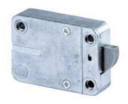
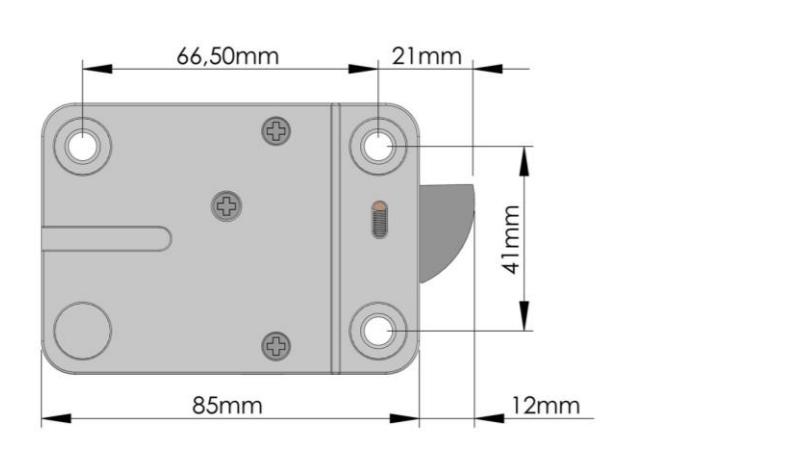
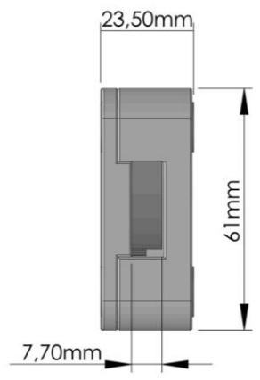
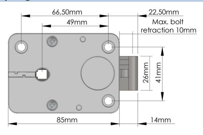
RotoBolt lock dimensions
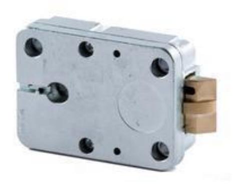
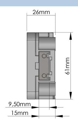
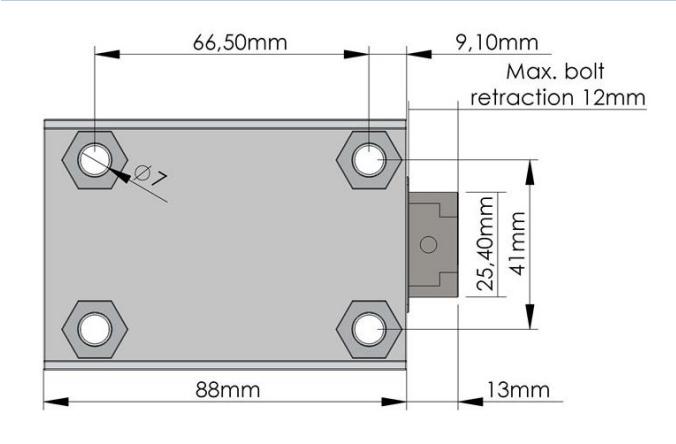
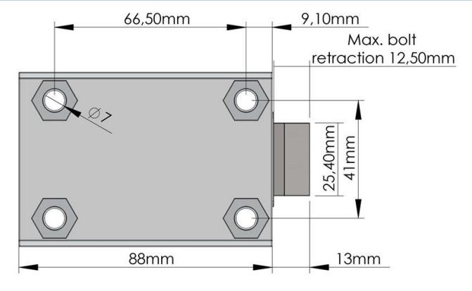
StraightBolt lock dimensions
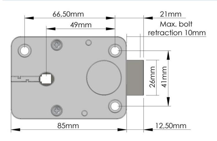
II_T4500_05_eng 5 di 12

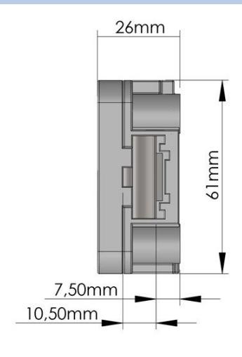
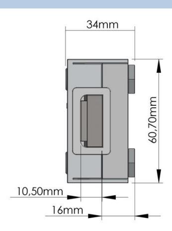
SpringBolt lock dimensions
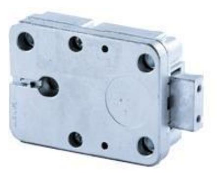
MotorLock lock dimensions
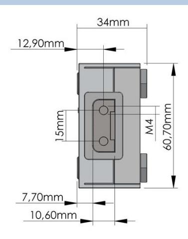
MotorSpringBolt dimensions

RotoBolt lock installation instructions
The RotoBolt lock is a swingbolt lock whose block is carried out by a motor; it can be installed in all 4 directions, even upside down.
By powering the lock, it removes the blocking and the boltwork can be moved into open position by pushing the bolt inside the lock case.
The bolt automatically secures when the safe handle, or the safe door mechanism, is brought to the locked position.
If the RotoBolt lock is used in conjunction with other locks, the safe door mechanism must ensure the closure of the RotoBolt before the other locks.
The lock can be mounted in all four mounting directions (RH, LH, VU, VD).
Furthermore, by flipping over the lock, both locking directions can be realized (RH/LH).
In the locked position the distance between the RotoBolt bolt and the RotobBolt part that is moving the lock bolt should be approximately 1 mm.
The bolt must be able to move freely without force being applied to it.
The maximum load applicable to the bolt must not exceed 1KN. Contact Tecnosicurezza in case of heavier loads.
II_T4500_05_eng 7 di 12

StraightBolt and SpringBolt locks installation instruction
StraightBolt and SpringBolt locks are locks with, respectively, a dead bolt and a spring bolt, whose block is carried out by a motor.
By powering the lock, it removes the blocking and the boltwork can be moved into open position by turning the spindle inserted in the lock.
The spindle can be connected to a knobor to a handle. When the spindle is brought to the locked position, the bolt comes out ensuring the lock is locked.
The StraightBolt and SpringBolt locks can be mounted in all four mounting directions.
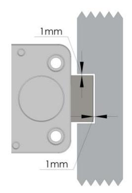
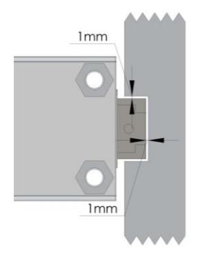
In the locked position, there should be approximately 1 mm clearance between the lock bolt and the cavity in the blocking bar of the boltwork. The bolt must be able to move freely without force being applied to it.
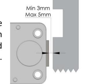
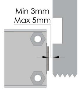
In open position, there should be minimum 3mm and maximum 5 mm clearance between the lock bolt and the blocking bar of the boltwork.
The maximum load applicable to the bolt must not exceed 1KN. Contact Tecnosicurezza in case of heavier loads.
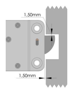
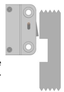
The spring-latch version (SpringBolt) is specially designed to ensure self locking when the door closes.
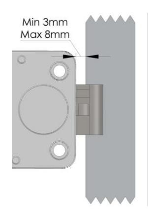
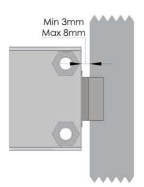
The distance between the SpringBolt lock and the locking edge must be between a minimum of 3 mm and a maximum of 8 mm.
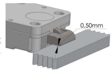
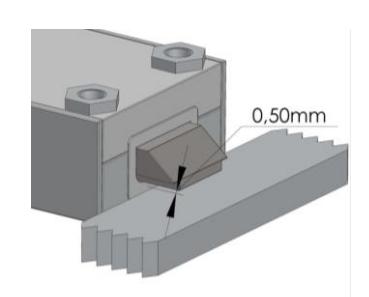
When locked, there must be a 0.5mm gap between lock bolt and locking surface.
The spindle must be inserted between a minimum of 7 mm to a maximum of 12 mm inside the lock.

MotorLock and Motor SpringBolt locks installation instructions
MotorLock and Motor SpringBolt locks are locks with, respectively, a motor driven dead bolt and a motor driven spring bolt, whose block is carried out by a motor.
By powering the lock, the motor retracts the bolt which remains in the open position for about 30 seconds and then automatically returns to the locked position.
In the locked position, there should be approximately 1 mm clearance between the lock bolt and the cavity in the blocking bar of the boltwork. The bolt must be able to move freely without force being applied to it.
In open position, there should be minimum 3mm and maximum 5 mm clearance between the lock bolt and the blocking bar of the boltwork.
The spring-latch version ( Motor SpringBolt) is specially designed to ensure self locking when the door closes.
The distance between the SpringBolt lock and the locking edge must be between a minimum of 3 mm and a maximum of 8 mm.
When locked, there must be a 0.5mm gap between lock bolt and locking surface.
II_T4500_05_eng 9 di 12

Characteristics and Cabling
Characteristics
The T4500 series is composed of RotoBolt, StraightBolt, SpringBolt and MotorBolt locks, whose block is realized through engine.
The power supply can be 9, 12 or 13.8 Volts.
Simply providing power supply, electronics instantly permits unlocking of the bolt.
The locks series T4500 can be mounted in all four directions (RH, LH, VU, VD). Further, by flipping the lock, both blocking directions can be realized (DX/SX).
The mounting dimensions are standard (magic module).
The lock is delivered with M6 metric mounting screws. Withworth screws 1/4 – 20 are available on demand.
Cabling
Power supply:
Red positive – Black negative. V = 9Vdc – 12Vdc – 13.8Vdc
I = 200mA @ 12Vdc
Maximum power supply time:
VERSION T4500, T4500/D, T4500/S
Tmax= 300sec @ 12Vdc (do not power it
for a longer time).
Bolt microswitch:
Blue cable – common
Red cable – normally open
Green cable – normally closed
Imax = 0,5A – Vmax = 50Vdc
Minimum power supply time:
VERSION T4500/M
Tmin= 40sec @ 12Vdc (do not power it for a
shorter time).
Functional test
To be carried out with the door open.
Provide power to the lock.
Turn boltwork handle towards OPEN position. Bolt must move freely.
Cut power to the lock.
Turn boltwork handle towards LOCKED position.
The lock bolt must fully extend and secure.
Make sure there is an air space on all sides of the lock bolt when the safe's boltwork is fully thrown into LOCKED position.
Repeat functional test several times before locking the safe door.
Failure to follow these installation instructions or opening the lock by personnel not authorized by Tecnosicurezza will void the warranty.


| NOTES |
|---|

Correct disposal of this product: (Waste Electrical & Electronic Equipment)
Applicable in the European Union and other European countries with separate collection systems.

This marking displayed on the product or its literature indicates that it should not be disposed with other wastes at the end of its working life.
To prevent possible harm to the environment or human health from uncontrolled waste disposal, please separate this from other types of wastes and recycle it responsibly to promote the sustainable reuse of material resources.
Contacts
GLOBAL HEADQUARTERS USA HEADQUARTERS SPAIN HEADQUARTERS
| Tecnosicurezza SpA | Tecnosicurezza Inc. | Tecnosicurezza Sa |
|---|---|---|
| Via Cesare Battisti. 276 | 50, Thomas Lane | C/Menor, 4 - Nave 10 |
|
37057 San Giovanni Lupatoto
Verona |
Versailles, KY 40383 |
Pol. Ind La Mina 28770
Colmenar Viejo |
| Tel.+39 045 826 64 70 | Tel.+1 859 490 89 30 | Tel.+34 91 804 33 91 |
| Fax. +39 045 826 64 69 | Fax.+34 91 804 32 63 | |
| info@tecnosicurezza.it | info@usatecno.com | info@tecnosicurezza.es |