Big Red Safe Locks CDL 3 and CDL 4 Mounting Instructions 010312
Open the original PDF document
View PDFBig Red® Safe Locks
"Big Red® , The Safe-Lock with the Red-Wheels" ®
Featuring DeadLoc Technology® ™
MOUNTING INSTRUCTIONS FOR LOCK MODEL CDL-3 AND CDL-4 GROUP 2 COMBINATION LOCKS :
WARNING! DO NOT REMOVE ANY INTERNAL PARTS. THIS IS A PRECISION MECHANISM WHICH SHOULD ONLY BE SERVICED BY A QUALIFIED SAFE TECHNICIAN. REMOVAL OR TAMPERING WITH ANY OF THE INTERNAL PARTS WILL VOID WARRANTY.
- 1. Remove the two Phillips head cover screws and Remove the lock cover and set it aside. Please read the complete instructions below before attempting to install the lock.
- 2. Align the spindle hole of the lock case with the spindle hole in the safe door and securely fasten the lock to the safe's mounting plate by installing a 1/4-20 machine screw at each of the lock case individual mount holes. After which, check to see that the lock case is firmly tightened against the safe door and will not move.
- 3. Mount the dial ring on the front of the safe door using two 8-32 machine screws. Carefully align the hole in the center of the ring as closely as possible with the spindle hole in the safe door. Note: A misaligned dial ring with the safe lock & safe door spindle hole will cause the dial to turn off center and the lock to operate non-smoothly.
- 4. Slide the Plastic Bushing over the dial spindle and seat it on the rear of the dial. Then insert the dial's spindle through the safe door and lock. Thread the spindle into the drive cam until the dial is snug in its ring and the drive cam is snug against the wheel post of the lock. Measure and note extra spindle length at the spot where the spindle first projects through the drive cam. Figure 2.

- 6. Insert the dial's spindle through the safe door and thread it into the drive cam until snug. The end of the spindle should now be nearly flush with the surface of the drive cam.
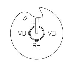
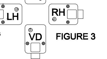
- 7. Back the cam off the spindle enough to align the slot (Spline Key) in the spindle with the slot in the drive cam which corresponds to the mounting position of the lock (RH, LH, VU, VD). If less than 1/2 turn is required to align the spline keyways, back the cam off one extra revolution. Figure 3.
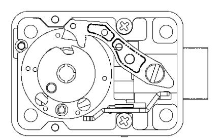
- 8. Insert a NEW, unused spline key into the aligned spindle and drive cam slots. The flag of the spline key should extend over the DIAL SPINDLE and NOT the body of the drive. Using a small, light hammer, tap the spline key until the flag just touches the surface of the dial spindle. Make certain the spline key is a tight friction fit, or the lock will not function properly. Figure 4.
- 9. Replace the lock's cover and fasten it securely with the cover screws.
- 10. Refer to operating and changing instructions for the model of lock you have installed.