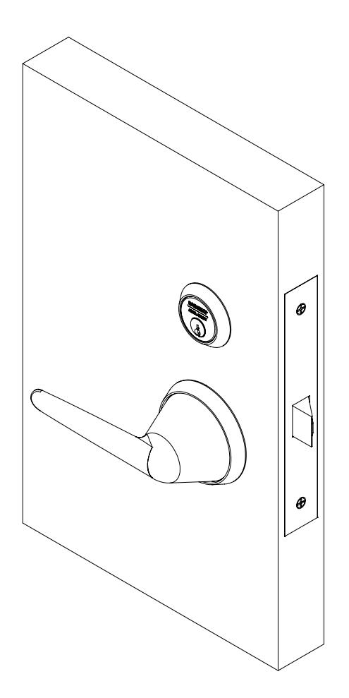
BHL Freewheeling Trim Retrofit (For Trim purchased prior to August 2019)
Open the original PDF document
View PDF

For Trim purchased prior to August 2019
8200 Series

This product can expose you to lead which is known to the state of California to cause cancer and birth defects or other reproductive harm. For more information go to www.P65warnings.ca.gov.
Copyright © 2019, SARGENT Manufacturing Company. All rights reserved. Reproduction in whole or in part without the express written permission of SARGENT Manufacturing Company is prohibited.
8200 Series
Installation Instructions

| TOC | Table of Contents | |
|---|---|---|
| 1 | Tools Required 3 | |
| 2 | Package Contents 3 | |
| 3 | Assembly 3 | |
| a | Prepare Spring Cartridges 3 | |
| b | Assemble Spring Cartridges into BHL Levers 4 | |
| c | Rose Handing 4 | |
| d | Assemble Outside Adapter Plate and Rose 5 | |
| 4 | Installation 5 | |
| a | Install Adapter Clutch 5 | |
| b | Install Outside Lever Assembly 5 | |
| c | Install Outside Trim 6 | |
| d | Install Inside Adapter Plate Assembly 6 | |
| e | Install Inside BHL Rose Assembly 7 | |
| f | Install Inside Lever Assembly 7 |
Attention Installer
Please read these instructions carefully to prevent missing important steps.
Notes
- Improper installation may result in damage to lock and void factory warranty.
- Other product brand names may be trademarks or registered trademarks of their respective owners and are mentioned for reference only.
8200 Series
Installation Instructions

1 Tools Required
- Phillips Screwdriver (# 2)
- Torx Tamper Resistant Driver (T-20)
- Torx Tamper Resistant Driver (T-10)
- Hex Key Driver 5/64"
2 Package Contents
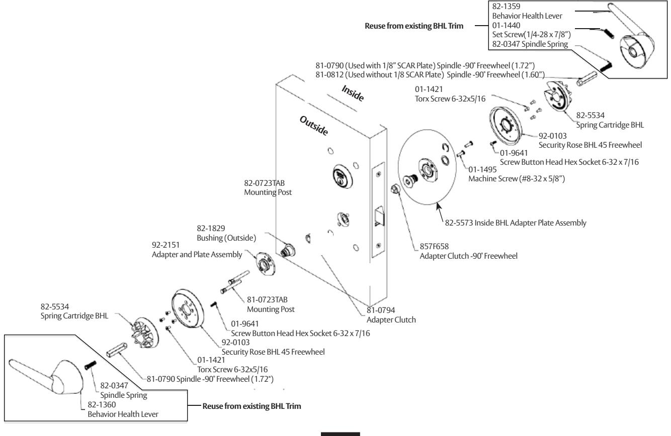
Figure 1
3 Assembly
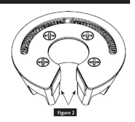
a Prepare Spring Cartridges
Remove clear adhesive tape liners from spring cartridges before use. ( Figure 2 )
1-800-727-5477 • www.sargentlock.com
A8259A 07/19
h
Installation Instructions

Finished Lever Assembly
3
Assembly (cont.)
b
Assemble Spring Cartridges into BHL Levers
Press spring cartridge assemblies into levers so that top of spring cartridge is flush or slightly below flush to lever's top surface. (Figure 3)
Note
Clean lever surface with rubbing alcohol prior to installing spring cartridge.
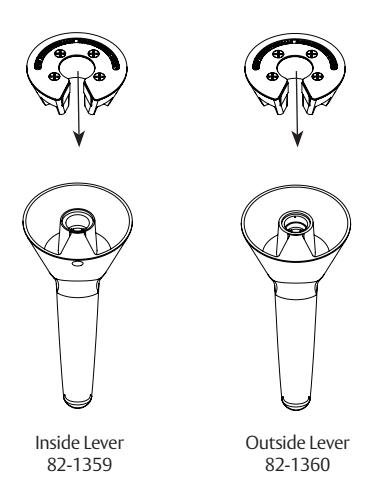

Figure 3
C
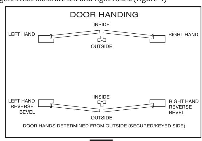
Rose Handing
• Review following figures that illustrate left and right roses. (Figure 4)
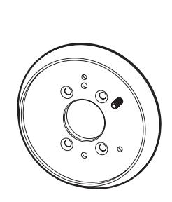
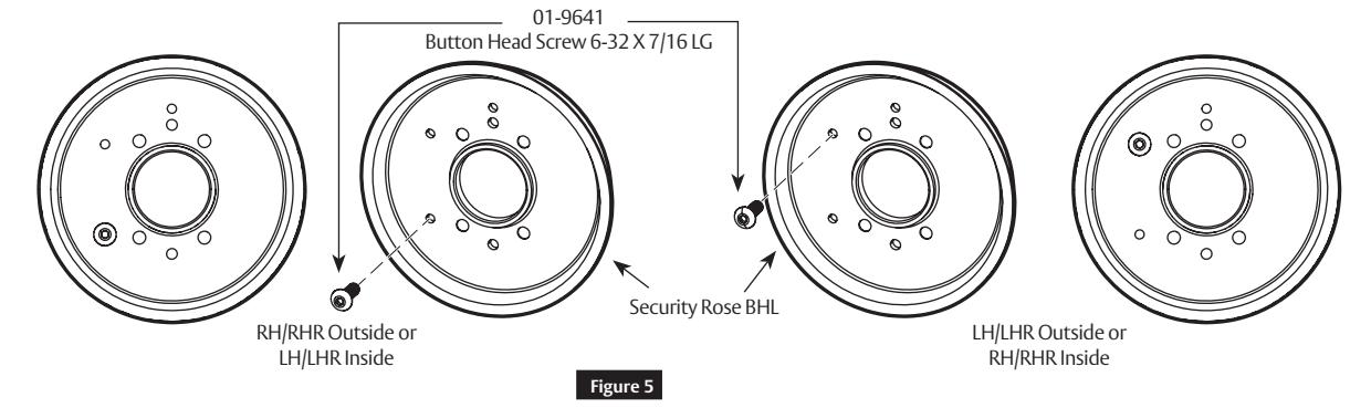
LH/LHR Outside or RH/RHR Inside
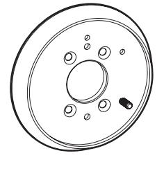
RH/RHR Outside or LH/LHR Inside
Figure 4
• Install button head screw into each rose. Use a 5/64" hex key to tighten screw firmly to rose. (Figure 5)
1-800-727-5477 • www.sargentlock.com
A8259A 07/19
8200 Series
Installation Instructions

3 Assembly (cont.)
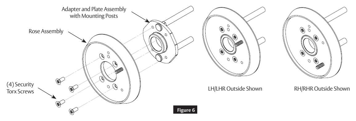
d Assemble Outside Adapter Plate and Rose
- Insert two (2) mounting posts into adapter plate. ( Figure 6 )
- Install rose using four (4) security torx screws.
Note:
Tighten screws evenly.
4 Installation
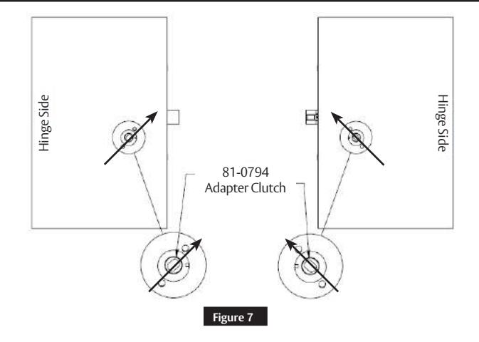
a Install Adapter Clutch
Install adapter clutch into mortise lock hub. (Figure 7 )
Note:
Adapter clutch is oriented toward latchbolt as shown.
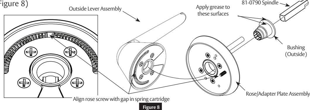
b Install Outside Lever Assembly
Use outside bushing and spindle to connect rose/adapter plate assembly to outside lever assembly. ( Figure 8)
A8259A 07/19 1-800-727-5477 • www.sargentlock.com
8200 Series
Installation Instructions

4 Installation (cont.)
b Install Outside Lever Assembly (cont.)
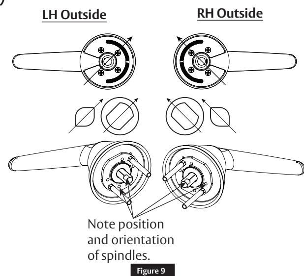
- Insert spindle into bushing; ensure that spindle is inserted no more than ¾" deep.
- Use spindle to rotate bushing clockwise into outside lever hole.
- Fully tighten bushing, then unthread bushing just enough to allow spindle to be inserted into lever, keeping bushing as tight as possible.
- Once assembled, spindle orientation should be as shown. ( Figure 9 )
Note:
Longer spindle used on outside
c Install Outside Trim
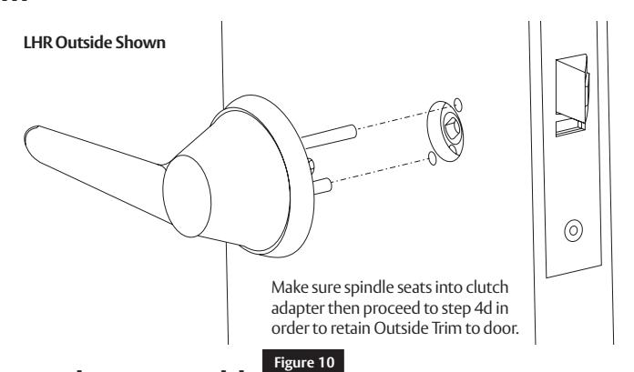
d Install Inside Adapter Plate Assembly
Install inside adapter plate assembly using two (2) machine screws. (Figure 11)
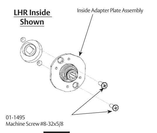
Figure 11
A8259A 07/19
1-800-727-5477 • www.sargentlock.com
8200 Series
Installation Instructions

4 Installation (cont.)
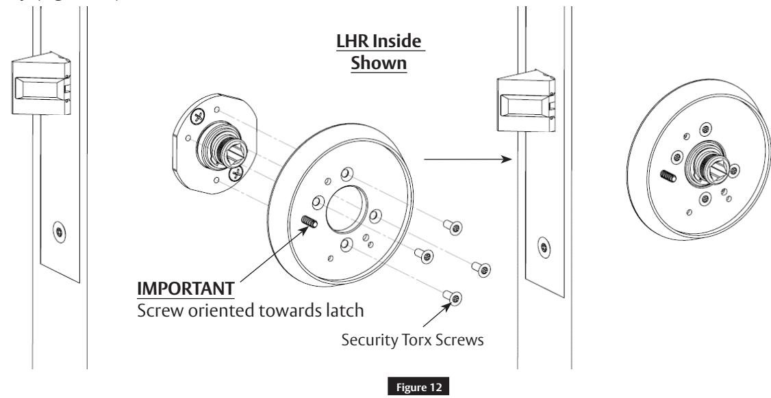
e Install Inside BHL Rose Assembly
Attach inside rose assembly to inside adapter plate using four (4) security Torx screws. Tighten screws evenly. ( Figure 12)
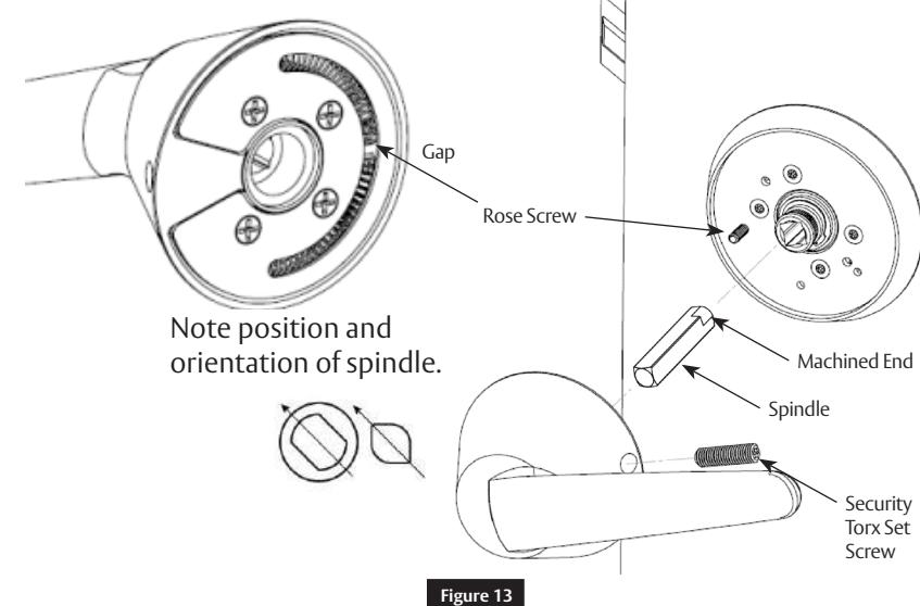
f Install Inside Lever Assembly
- Install inside Spindle. (Figure 13 )
- Install inside BHL lever assembly to inside adapter plate assembly using security torx set screw.
IMPORTANT
- Line up rose screw with gap on spring cartridge.
- Make sure machined end of spindle seats into clutch adapter before assembling lever onto rose. ( Figure 13 )
Note
- Inside of LHR shown.
- Shorter spindle used on inside.
1-800-727-5477 • www.sargentlock.com
A8259A 07/19

SARGENT Manufacturing Company 100 Sargent Drive New Haven, CT 06511 USA 800-727-5477 www.sargentlock.com
Founded in the early 1800s, SARGENT® is a market leader in locksets, cylinders, door closers, exit devices, electro-mechanical products and access control systems for new construction, renovation, and replacement applications. The company's customer base includes commercial construction, institutional, and industrial markets.