BEST V Series Offline Lock User Guide
Open the original PDF document
View PDF

B.A.S.I.S.® Offline User Guide

Copyright©2014 Stanley Security, Inc. All rights reserved.
Information in this document is subject to change without notice and does not represent a commitment on the part of Stanley Security Solutions, Inc. The software described in this document are furnished under a license agreement or nondisclosure agreement.
This publication is intended to be an accurate description and set of instructions pertaining to its subject matter. However, as with any publication of this complexity, errors or omissions are possible. Please call SSS Technical Support Group at 1-800-392-5209, if you see any errors or have any questions. No part of this manual and/or databases may be reproduced or transmitted in any form or by any means, electronic or mechanical, including photocopying, recording, or information storage and retrieval systems, for any purpose, without the express written permission of Stanley Security, Inc.
This document is distributed as is, without warranty of any kind, either express or implied, respecting the contents of this book, including but not limited to implied warranties for the publication's quality, performance, merchantability, or fitness for any particular purpose. Neither Stanley Security, Inc, nor its dealers or distributors shall be liable to the user or any other person or entity with respect to any liability, loss, or damage caused or alleged to be caused directly or indirectly by this publication.
The Best Access Systems logo and B.A.S.I.S.® are registered trademarks of Stanley Security, Inc.
Microsoft Windows, CE, Mobile Device Center, and ActiveSync are registered trademarks of Microsoft Corporation.
T80946-D 2014
Contents
| 5 | Overview |
|---|---|
| 7 | How B.A.S.I.S. Readers Work |
| 10 | Feature Comparisons of B.A.S.I.S. G and V |
| 12 | Setup Checklist |
| 13 | Installation and Configuration |
| 14 | Needed Components |
| 15 | Task 1: Install B.A.S.I.S. Software |
| 15 | Task 2: Install Encoder |
| 18 | Defining the system |
| 19 | Task 3: Define Card Formats |
| 22 | Task 4: Define Badge Types |
| 26 | Task 5: Define Offline Access Panels |
| 28 | Task 6: Define the Guest Locks/Readers |
| 39 | Task 7: Install B.A.S.I.S. Transport |
| 49 | Task 8: Installing B.A.S.I.S. Transport for PDA |
| 62 | Task 8: Install B.A.S.I.S. Transport for Netbook/Notebook |
| 67 | Set Up and Maintain Offline Locks |
| 68 | Transferring Lock/Reader Configurations |
| 69 | Transferring Lock/Reader Configurations to the PDA |
| 69 | Connecting the PDA to the Lock/Reader |
| 88 | Transferring Lock/Reader Configurations to the Netbook/Notebook |
| 94 | Connecting the Netbook/Notebook to the Reader |
| 116 | To Manually Change the PIN in a Dual Validation Lock |
| 117 |
Managing B.A.S.I.S.
Cardholders |
| 118 | Creating Cardholders |
| 121 | Searching for Cardholders |
| 123 | Encoding Existing Cardholders |
| 127 | Glossary |
1 Overview
This manual is your guide to B.A.S.I.S. Offline System.
The information in this guide is presented in a linear manner; however, tasks to install hardware and software and configure the system for the first time do not necessarily progress in a linear manner. You will find a Setup Checklist at the end of this section to take you through the initial setup and configuration tasks in a logical sequence.
B.A.S.I.S. Online and Offline Diagram
The B.A.S.I.S. system is capable of being configured as both an online and an offline access control system. This means that with B.A.S.I.S., you can manage any access control hardware, whether they are wired directly to a panel or not.
This diagram describes a typical combined online and offline B.A.S.I.S. system.
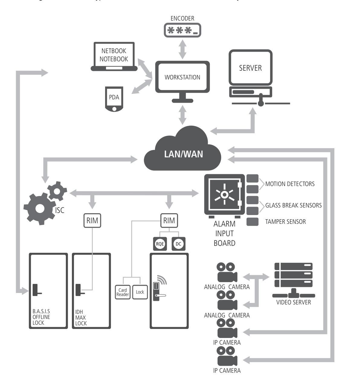
Figure 1 B.A.S.I.S. online and offline diagram overview
Overview 6
How B.A.S.I.S. Readers Work
B.A.S.I.S. G
B.A.S.I.S. G offline locks are designed primarily for the college/university dormitories . However, they can be effectively used in any application where a room has continuous occupancy change over a period of time, or where the lock location is remote or isolated enough that going out to reprogram the lock becomes undesirable.
Guest functionality is the lock feature that enables you to add and delete users to and from the lock without having to go out and visit the lock to reprogram it.
Operation
B.A.S.I.S. G allows a range of per-programmed badge numbers access into a locked unit that secures a dormitory room. These badge numbers are available for issue and reuse as students are assigned to their dormitory accommodations. The badge number is automatically issued to a student when the lock for the room is chosen in the cardholder setup screen. The card number from the assigned range can then be encoded and presented to the student for use in his or her assigned room.
New students may be assigned access to a particular room by using badge IDs from the same range without ever needing to reprogram the lock. By taking advantage of the issue code look ahead feature, a badge ID issued with an incrementally higher issue code will deactivate any other like badge ID for the lock.
The following diagram describes the design and process that B.A.S.I.S. G locks use to achieve the guest functionality.
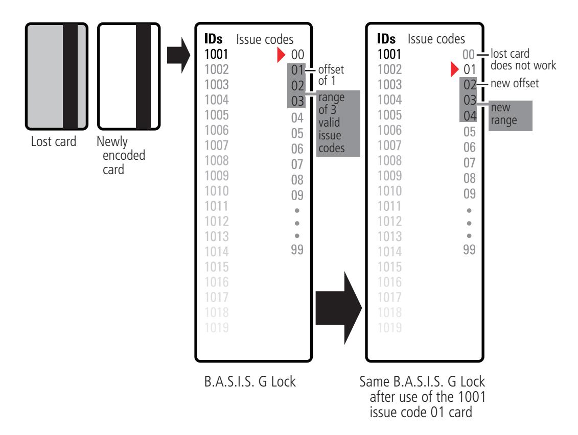
Figure 2 Guest functionality diagrammed
The diagram uses the following issue code look ahead values:
| Look ahead function | Value |
|---|---|
| Offset | 1 |
| Range | 3 |
| Number of issue code digits | 2 |
The next diagram shows what happens when the issue code has reached its limit. The issue code look ahead values remain the same.
Overview 8
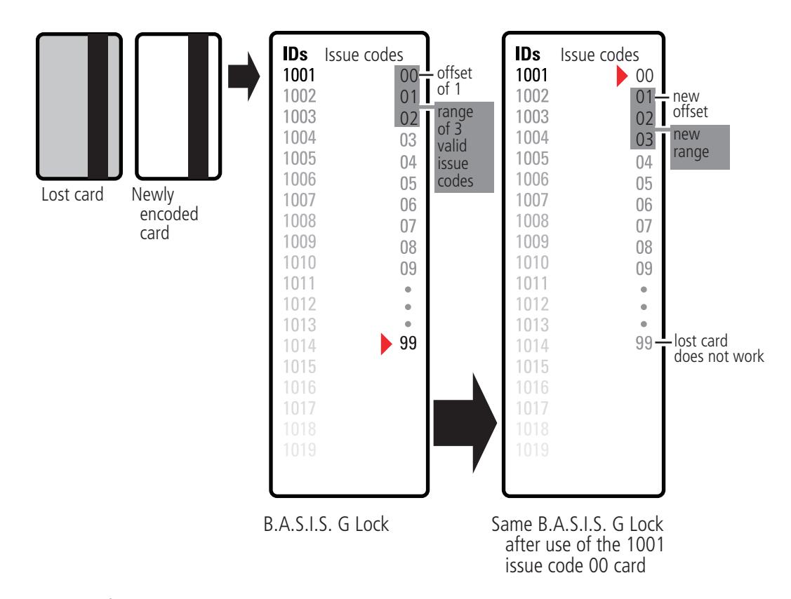
Figure 3 Guest functionality diagrammed
B.A.S.I.S. V
B.A.S.I.S. V offline locks are designed to include all functions of B.A.S.I.S. G (including Guest Functionality as described in previous section), plus upgraded features. On the following page, the 'Feature Comparisons of B.A.S.I.S. G and V' table compares the systems.
Feature Comparisons of B.A.S.I.S. G and V
| Feature | Description | G | V |
|---|---|---|---|
|
Guest (dormitory
feature) |
Provides the ability to issue pre-created badge IDs to students. This supports the
assignment of one reader directly to the badge. Other readers may be assigned to the badge through normal access level assignment. |
| |
| Look ahead | Issue code look ahead feature through offset and range fields. | | |
| Encoding | Provides the ability to encode both magstripe. | | |
| Passage mode |
Allows the cardholder to place the reader into an unlocked mode. This status is
cleared only by another passage mode attempt or reader mode change occurrence. |
| |
| Deadbolt override | Allows the cardholder to retract the deadbolt | | |
| Key override event |
An event logged into history whenever the key override feature is used in a
mortise lock. Not supported in Cylindrical. |
| |
| Use activation date |
Determines if the lockset will use the activation date field stored in the cardholder
record when validating. This option has no impact on Dormitory functionality. |
| |
| Use deactivation date |
Determines if the lockset will use the deactivation date field stored in the
cardholder record when validating. This option has no impact on Dormitory functionality. |
| |
| Two card control | Requires that two valid users must present their cards in order to unlock the door. | | |
| Enforce use limit |
Allows for the temporary use of cards. After a certain number of uses the card is
disabled. The number of uses is configured through the badge tab. |
| |
| Denied attempts |
Includes attempts count and time out duration. Sometimes referred to as 'Three
strikes you're out'. |
| |
|
Logging (grant denies,
status) |
Provides the ability to filter the displaying/logging of history events. This feature is
implemented at the Management System level. |
| |
| Daylight savings time | Support for all OS world time zones. | | |
| 128K RAM | 5000 Users/History | | |
| Card formats (8) |
Support for up to eight card data formats per reader. Facility codes are assigned
through card formats. |
| |
| Magnetic | 5 bit ABA data only. |
track
3 |
track
1&2 |
| Wiegand | Any valid Wiegand format. | | |
| Online mode |
Automatic (time zone control of reader mode), Facility Code, Card Only, Unlocked,
Locked, Card and Pin, and Card or Pin. |
| |
|
Reader mode
(automatic unlock/ relock) |
This feature provides the ability to change (automatic
operational modes at specified periods through unlock/relock) time zone control. The current modes would be Facility Code, Card Only, Unlocked, Locked, Card and Pin, Card or Pin, and First Card Unlock. |
2 | 32 |
| Unlock duration | The amount of time that the lock set will remain unlocked for a valid access grant. | | |
| Extended unlock |
This feature provides the ability to extend the unlock duration for certain
cardholders. |
| |
| Chassis type | Cylindrical & Mortise with support for a user defined type 'Custom'. | | |
|
Automatic Chassis
Volume |
Chassis volume automatically corresponds to the chassis type chosen. | ||
| Holidays | Special days of the year can be categorized as one of the eight types. | 8 | 32 |
| Time Zones |
Time Zones are necessary for the use of Access Levels. A time zone can be
comprised of up to six intervals. |
4 | 32 |
| Access levels | Access Level assignment to readers. | | |
| Battery warning/alarm | Reported through the activation of LED's and the lock internal sounder. | | |
Overview 10
| Panel password | Communication password is configured at the Access Panel level. | | |
|---|---|---|---|
|
Diagnostics (PDA or
Netbook/Notebook) |
The PDA or Netbook/Notebook will support the capability of performing
diagnostics on the lock set. |
| |
| Cycle count/reset |
The lock set will maintain a current count of access grants. The count can be
reset by the user. |
| |
| Diagnostics code | This code provides some feedback of the lock set's status. | | |
| Backup battery level | Displays the current level of the backup battery. | | |
| Electronics level | Displays the current level of the main battery. | | |
| Unlock once | This feature allows for the unlocking of the door for the unlock duration. | | |
| Reader mode |
This feature allows for the setting of the current operating mode directly to the
reader through the PDA or Netbook/Notebook. This action would override the online mode set at the management system level. All online reader modes are supported. |
| |
| Reader support | Dual Validation | | |
| Magstripe |
track
3 |
track
1&2 |
|
| HID Proximity | | ||
| Motorola Proximity | | ||
| Batch Update | This feature allows for the bulk updating of Activation/Deactivation Dates. | | |
Setup Checklist
In the next chapter you will find complete step-by-step instructions for the first-time installation and configuration of a B.A.S.I.S. offline system. Listed below are the major steps of that process.
- Task 1: Install B.A.S.I.S. Software See page 15.
- Task 2: Install Encoder See page 15.
- Task 3: Define Card Formats See page 19.
- Task 4: Define Badge Types See page 22 .
- Task 5: Define Offline Access Panels See page 25 .
- Task 6: Define Guest Locks/Readers See page 27 .
- Task 7: Install B.A.S.I.S. Transport See page 38 .
- Task 8: Install B.A.S.I.S. Transport on PDA or Netbook/Notebook See page 48 or page 60 .
Overview 12
2 Installation and Configuration
This chapter will guide you through performing the following tasks:
Task 1 — Install B.A.S.I.S. Software
Task 2 — Install Encoder
Task 3 — Define Card Formats
Task 4 — Define Badge Types
Task 5 — Define Offline Access Panels
Task 6 — Define Guest Locks/Readers
Task 7 — Install B.A.S.I.S. Transport
Task 8 — Install B.A.S.I.S. Transport on PDA or Netbook/Notebook
Needed Components
The following describes the hardware and software that it takes to create an offline B.A.S.I.S. system.
Components include:
- B.A.S.I.S. ET691 software, or higher
- Dedicated computer or 'workstation' (consult your Stanley representative for complete details)
- B.A.S.I.S. G or V lock(s), includes cylindrical, mortise or exit hardware trim models
- Personal digital assistant (PDA) or Netbook/Notebook. See www.bestaccess.com for supported models
- Encoder
- Magnetic Stripe encoder: Unitech Model MSR206
- Cables
- PDA to lock (requires PDA programming cable, proprietary cable). See "Figure 54 Connecting the PDA to a lock" on page 67.
- Netbook or Notebook to lock (requires USB to Serial programming cable, Null Modem Serial Cable-female to female, and programing cable). See "Figure 94 Connecting the Netbook/ Notebook to a lock" on page 94 .
Task 1: Install B.A.S.I.S. Software
For complete B.A.S.I.S. software installation and configuration, see the B.A.S.I.S. Installation and Setup User Guide. Contact your Stanley Representative for a copy or visit www.bestaccess.com .
Task 2: Install Encoder
One types of encoder is available for the B.A.S.I.S. Offline system:
• Magnetic Stripe encoder: Unitech Model MSR206
The card encoder or some type of encoding device (that is, an encoder or a printer with a built-in encoder) is intended for B.A.S.I.S. G locks. So the following instructions are required for B.A.S.I.S. G functionality, but optional for B.A.S.I.S. V. For a comparison of B.A.S.I.S. G and V, see "Feature Comparisons of B.A.S.I.S. G and V" on page 10 . The following instructions are for a stand-alone encoder.
Perform the following steps to set up the encoder:
- Click Start > Programs > B.A.S.I.S. ET > System Administration.
- At the login window, type your user name and password and then click OK. If you do not know your user name or password, see your System Administrator.
- Click Administration > Workstations.
- From the Workstation tab, confirm that the name of your computer is in the list. If your computer is not in the list, add your workstation by using the browse button and select your workstation.
- Click Add.
- Type the name of your computer or click the browse button and browse the network for your computer.
- Click OK.
- Click the Encoders/Scanners tab.
- Select the General tab and name your encoder under the encoder settings.
- Make sure that your workstation is selected under the Workstation setting.
- Under Device type, select your device. Credential technology should automatically select Magnetic.
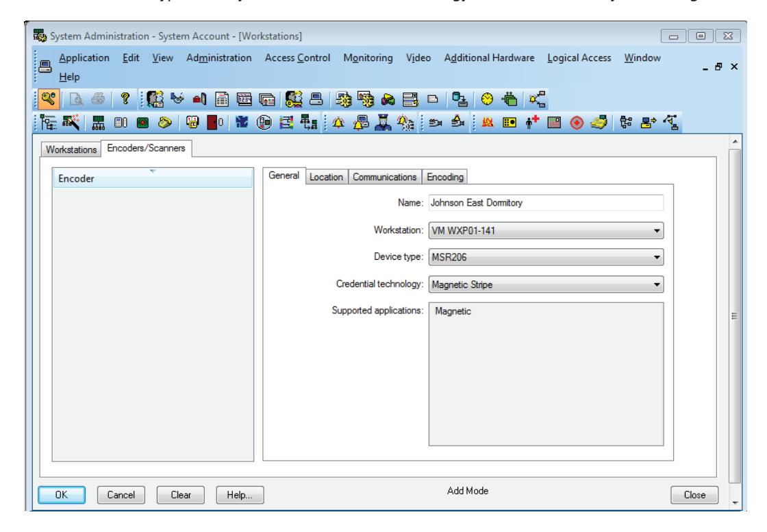
Figure 4 Device type
Confirm that the encoder is physically connected to a COM port on the computer, by selecting the Communication tab.
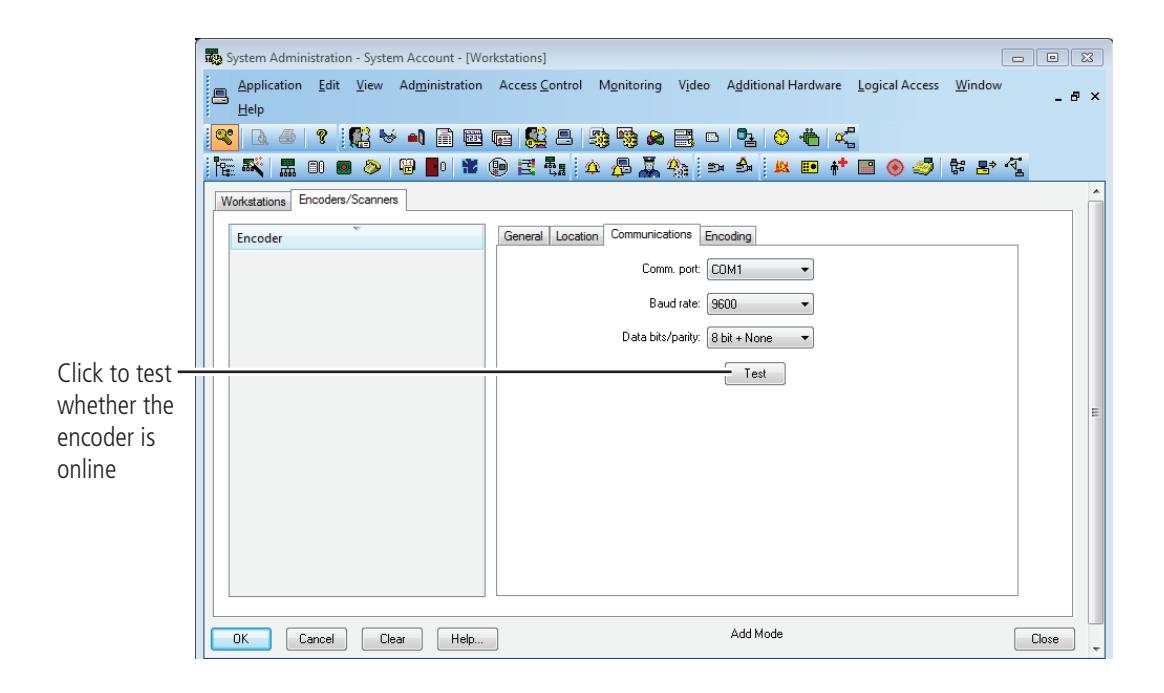
Figure 5 Configuring the encoder
13 Click Test.
Note The encoder can be tested at any time by returning to the Encoder tab. You do not need to put the encoder in modify mode to test the encoder. The corecitivity setting must be selected as "High" on the Encoding tab.
14 Click OK.
Defining the system
To define a B.A.S.I.S. offline system, you need to configure:
- Card Formats
- Badge Types
- Guest Readers
- Offline Access Panels
- Timezones
- Access Levels
- Adding a cardholder
Although B.A.S.I.S. locks are offline (stand-alone) and are not managed by access control panels, you must define Access Panel settings for the locks. In effect, you define access control panels for the locks. More than one lock – called a reader in B.A.S.I.S. — can share the same panel configuration. However, these locks (readers) must all:
- be managed by the same Server or Workstation
- share the same password
- be located in the same time zone
- use the same daylight savings time setting.
Task 3: Define Card Formats
Defining a card format is the starting point to configure guest access control. If guest access control is not needed, a standard card format can be used or configured for a reader assignment through access levels. Badges using standard formats on compatible tracks can only be assigned readers through access levels. Perform the following steps:
1 From System Administration, click Administration > Card Formats.
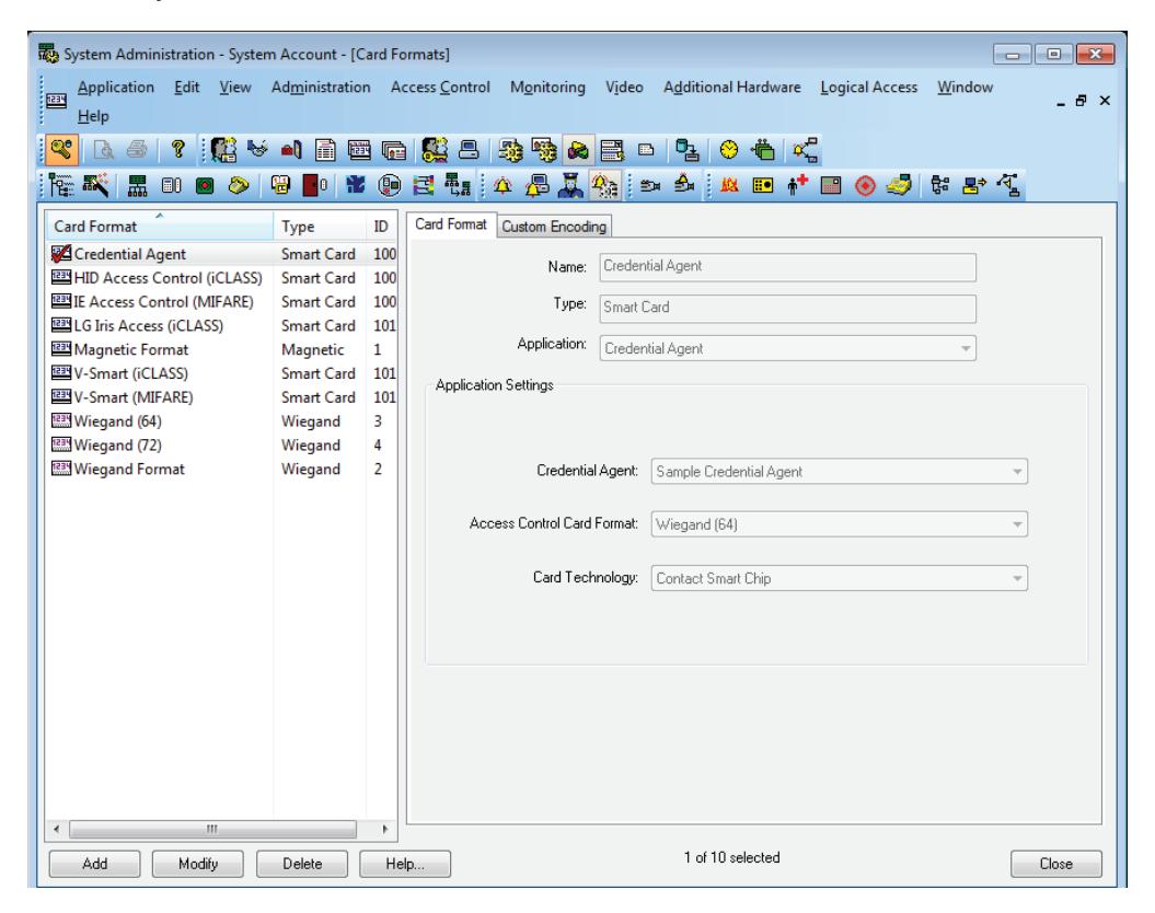
Figure 6 Card format
2 Click Add.
The Card Format form displays:
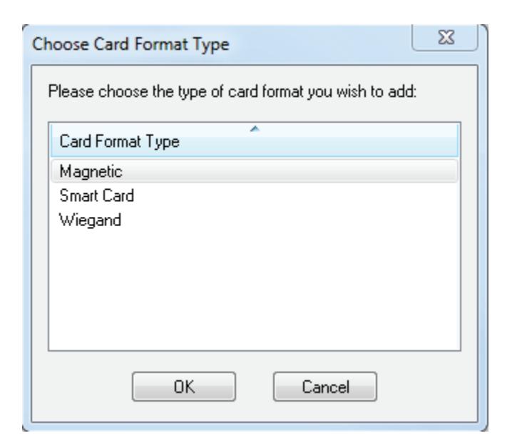
Figure 7 C hoose card format type
3 Choose the appropriate card format and click OK.
When the guest format check box is selected, the data is offset from the start of the card by the fact that the activation and deactivation dates are encoded onto the card.
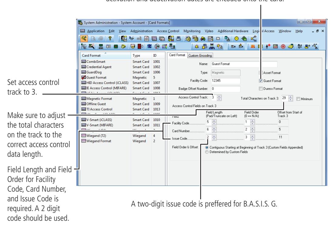
Figure 8 Defining card formats
- 4 Type the name of the card format. A typical name for the guest format is 'Guest format.'
- 5 Complete all appropriate fields including field length and field order for facility code, card number, and issue code.
Task 4: Define Badge Types
To use B.A.S.I.S. G offline lock basic functionality, you must define a guest badge type. This badge type allows you to define and allocate a range of badge ID numbers that will be programmed into the lock. Badge type is an ID Credential Center function used in the configuration of Guest products and determines the block or pool of badge numbers to be allocated to a group of locks.
Also, badge type determines the card format to be encoded on the badge. In this instance, think of the badge type as a way of allocating a block of badge numbers to a facility, building, or other group of related guest locks.
Note A badge type could be used to allocate a pool of badge numbers for a dormitory from which smaller blocks of numbers could be obtained for the individual dormitory units.
Perform the following steps:
- 1 From System Administration, click Administration > Badge Types.
- 2 Click Add.
The modify badge type window displays.
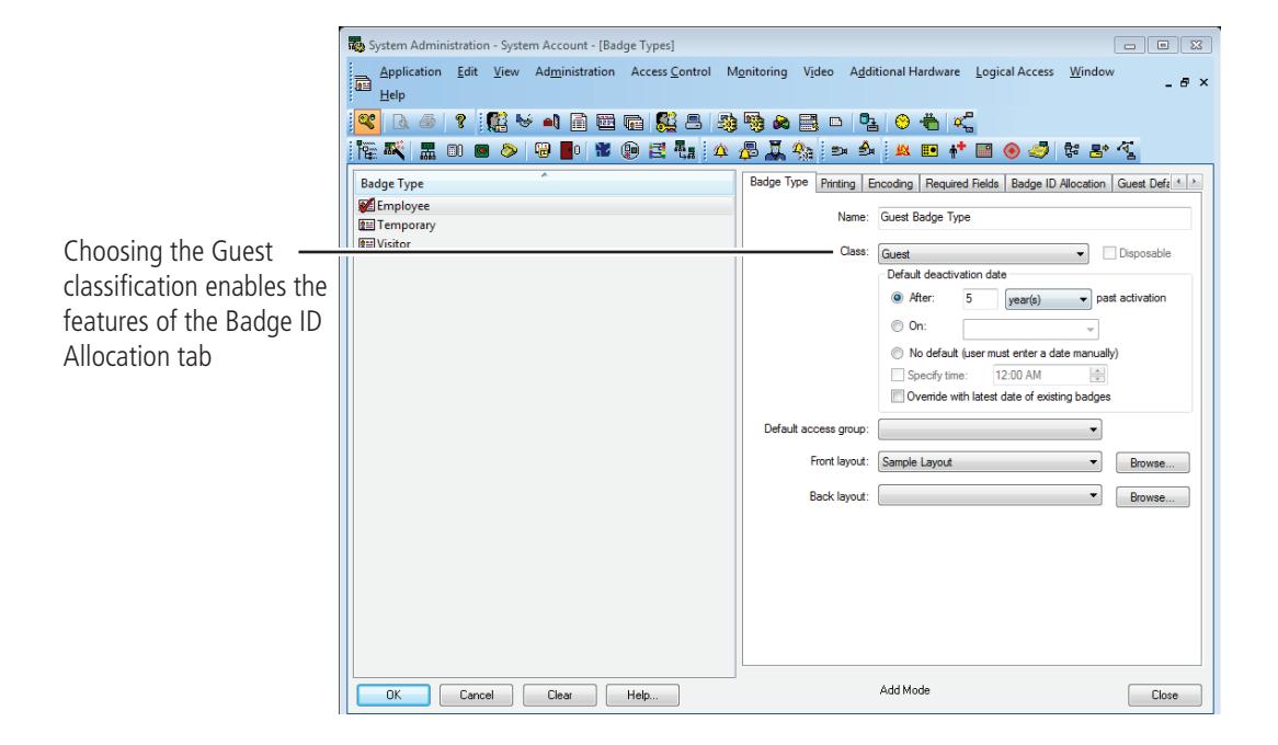
Figure 9 Selecting the Guest class for B.A.S.I.S. G badge type
- 3 Select the Guest class from the drop down box.
- 4 Complete all other necessary information on the tab.
- 5 Click the Encoding tab > Click Add
- 6 Select the appropriate card format to be encoded for the badge type by clicking the icon to the left of the "Guest Format". A red arrow will appear over the card illustration > Click OK
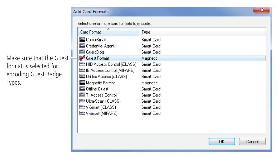
Figure 10 Add card formats
7 Click the Badge ID Allocation tab and then click the ID Ranges tab.
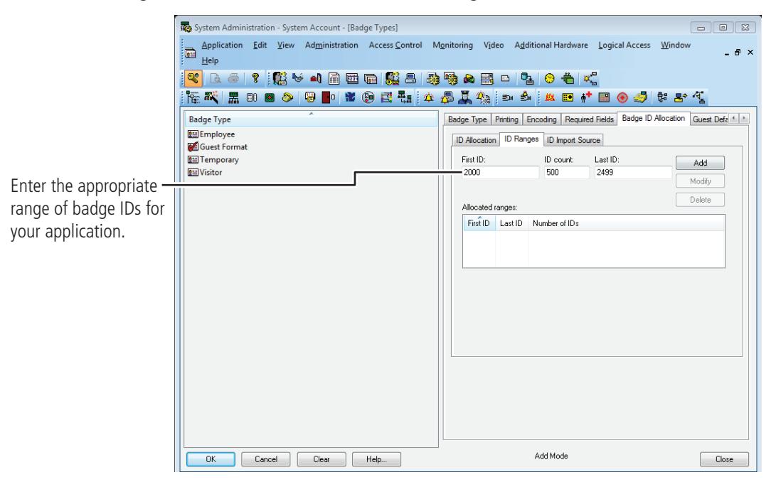
Figure 11 Entering the range of Badge IDs
8 Enter the First ID number in the badge range that you want to create
Note Make sure to allocate a range of badge numbers that will facilitate the future growth of a group of locks. The size of the range will determine the length of the reader list in the 'Allow Access To' dropdown selection on the Badge tab under Cardholders.
- 9 In the ID Count field, enter the number of Badge IDs that you want to create.
- 10 Click Add.
- 11 Click OK.
Task 5: Define Offline Access Panels
Although B.A.S.I.S. Locks are offline (stand-alone) locks and are not managed by access control panels, you must define Virtual Access Panel settings for the locks. Using the access panel concept allows the programming of guest locks to follow the same conventions as B.A.S.I.S. online products. Up to 64 locks (called readers in B.A.S.I.S.) can share the same panel configuration. However, these readers must all:
- be managed by the same Server or Workstation
- share the same password
- be located in the same time zone
- use the same daylight saving time setting.
Note The default password is 'BEST.' Care should be given to faithfully document any changes to this password since the password cannot be viewed from anywhere in the B.A.S.I.S. application software.
Perform the following steps:
- 1 From System Administration, click Access Control > Access Panels.
- 2 Click the Offline Lock tab.
- 3 Click Add.
The Offline Lock Access Panel window displays.
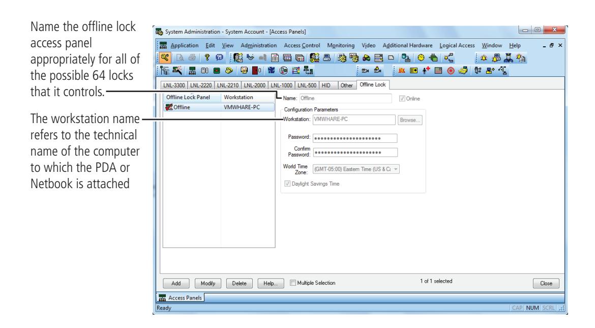
Figure 12 Naming the offline lock access panel.
- 4 In the Name field, type the name of the access control panel.
- 5 Click OK.
- 6 Repeat steps 3 and 4 as necessary.
Task 6: Define the Guest Locks/Readers
In the B.A.S.I.S. software, locks are referred to as readers to conform and maintain consistency with B.A.S.I.S. online terminology conventions.
You can define up to 64 readers for each 'virtual' offline access control panel. And each reader will accept up to eight different card formats. It would be highly unusual to use this many formats in one lock. Perform the following steps:
- 1 From System Administration, click Access Control > Readers and Doors.
- 2 Click Add.
The Add Reader window displays.
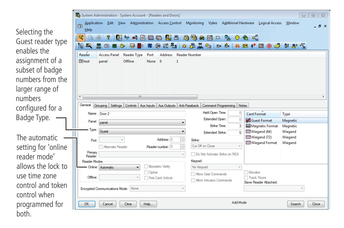
Figure 13 Defining offline guest readers
- 3 In the Name field, type the name of the reader.
- 4 In the Panel field, select the virtual offline access control panel that controls the reader.
- 5 In the Type field, select Guest.
- 6 Select the appropriate reader mode.
- 7 Under the Card Format section, select the Guest Card Format.
Note Selecting the 'Offline Guest' reader type refers to a B.A.S.I.S. G configuration.
- 8 Make any other selections as necessary.
- 9 Click OK.
The Reader is listed in the Reader listing at the top of the window.
10 Repeat steps 3 – 10 for each additional lock/reader.
Now that you have defined the reader operation of the lock/readers, you now need to configure the software so that the correct chassis type is assigned to the lock/reader and other offline features are configured appropriately.
Before you can complete this section you must know:
- Chassis type of the lock/reader. The chassis type will only be either mortise or cylindrical.
- The maximum number of cardholders that will need to access the lock/reader. This includes both guest cardholders and those cardholders that access the reader by access levels.
- The number of guest badges that will be assigned from the pool of badge IDs.
Define Other Guest Reader Features
- 1 From System Administration, click Access Control > Readers and Doors.
- 2 Select the Reader that you want to define. Make sure that the check mark is next to the reader to be modified.
- 3 Click the Offline tab.
- 4 Click Modify.
The Modify Offline Reader window displays.
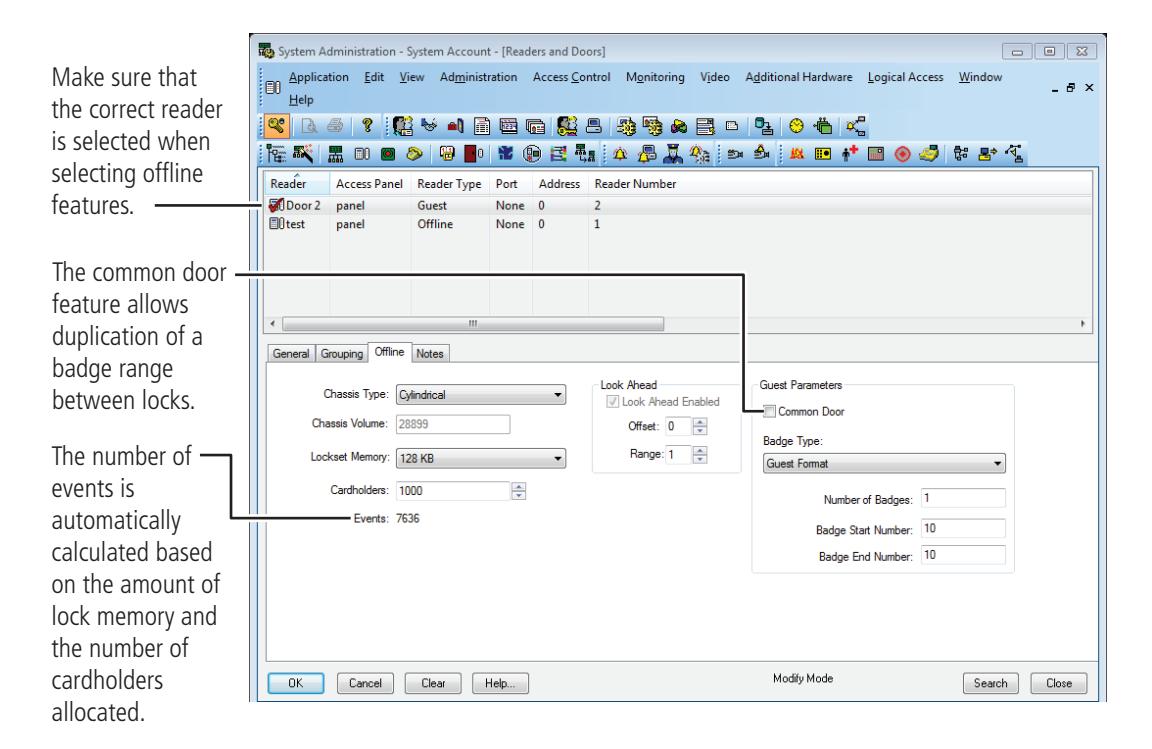
Figure 14 Defining the offline reader
5 In the Chassis Type field, select the chassis type that the lock/reader has.
Note The custom chassis type enables the modification of the chassis volume. The chassis volume is a value used by engineers that relates to the number of turns of the motor that is required to unlock the lock. Only use the custom chassis type at the direction of a technical support engineer or specific instructions enclosed with the lock.
- 6 In the Cardholders field, select the total number of cardholders that will need to access the lock/reader.
- 7 In the Look Ahead section, select the look ahead offset and range. Normally for B.A.S.I.S. G locks, the offset is set to 1 and the range to 3.
- 8 The Guest Parameters section, select whether the reader will be a Common door.
- 9 In the Badge Type field, select a guest badge type from the list that was created. See page 21 .
- 10 In the Number of badges field, enter the number of guest badges to be allocated to this reader from the total pool of badge IDs.
- 11 For a common door only : In the Badge Start Number field, enter the starting badge number for the subset of numbers to be used in this reader. The badge end number is automatically calculated from the numbers entered.
- 12 Click OK.
- 13 Repeat steps 3 12 for each reader to be defined.
Define Timezones
A timezone is a block of time that a particular activity or function is allowed to occur. These blocks of time are represented by intervals.
B.A.S.I.S. Access Control system can be configured for up to 255 timezones limited by the feature set of each product.
Add a timezone
1 From System Administration, click Access Control > Timezones
The Timezones window displays
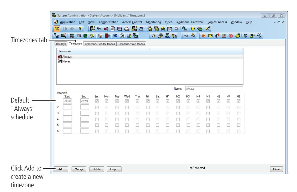
Figure 15 Timezone window displaying the "Always" schedule.
- 2 Click the Timezones tab. A list of the existing timezones will be displayed.
- 3 Click Add to create a new timezone to the list.
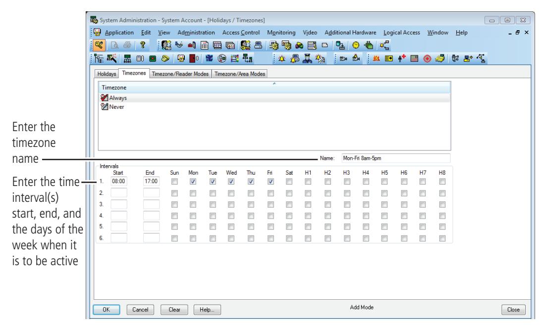
Figure 16 Adding a timezone
- 4 Choose a name for the timezone and enter the choice in the Name field.
- 5 Choosing a name that actually represents the period of time for the timezone allows you to efficiently retrieve a timezone from a long list. The timezone list can include up to 255 different timezones.
- 6 Enter the desired start and end times for each desired interval (time must be entered in a 24-hour format). Indicate by checking the check box on each day that you want the interval to be active.
- 7 Click OK
The new timezone has been added to the list.
Notice the Timezones tab has additional headings for something other than standard days of the week. These H1-H8 represent holidays that allow for the exceptions to each interval. These holidays, or exception days, are configured on the Holiday tab.
B.A.S.I.S. organizes these exception days into one of eight types. Those exception days that are to be treated the same would be organized into one of eight types. A holiday type can contain more than one configured exception period.
Access Levels
An Access Level is nothing more than a list of relationships between readers and timezones. These access levels will become assigned to badges and will determine whether or not a badge will unlock a door during a specified time.
Add access levels
1 From System Administration, click Access Control > Access Levels
The Access levels window displays
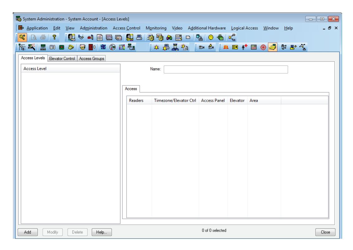
Figure 17 Access level
2 Click Add to create an access level.
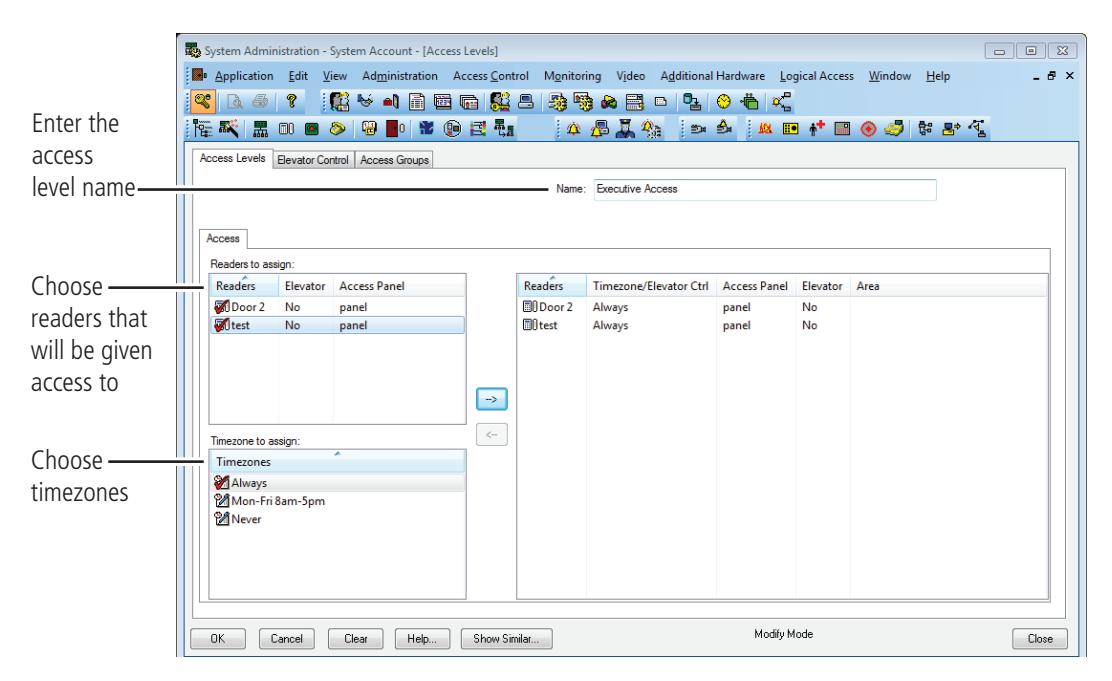
Figure 18 Access level
- 3 Choose a name for the access level and enter the choice in the Name area.
- 4 Select the reader and the timezone configuration to be included in the access level. Remember that a selection is not made unless a checkmark is observed.
- 5 Click on arrow button to the right to move the reader and timezone selections to the right side of the form.
- 6 Click OK to save the record.
Adding a Cardholder for Standard Access Control
Add a cardholder for standard access control
1 Open System Administration and go to Administration > Cardholders.
A page with several tabs will be displayed. We are only concerned with the first three tabs of Cardholder, Badge, and Access Levels for common day-to-day entry.
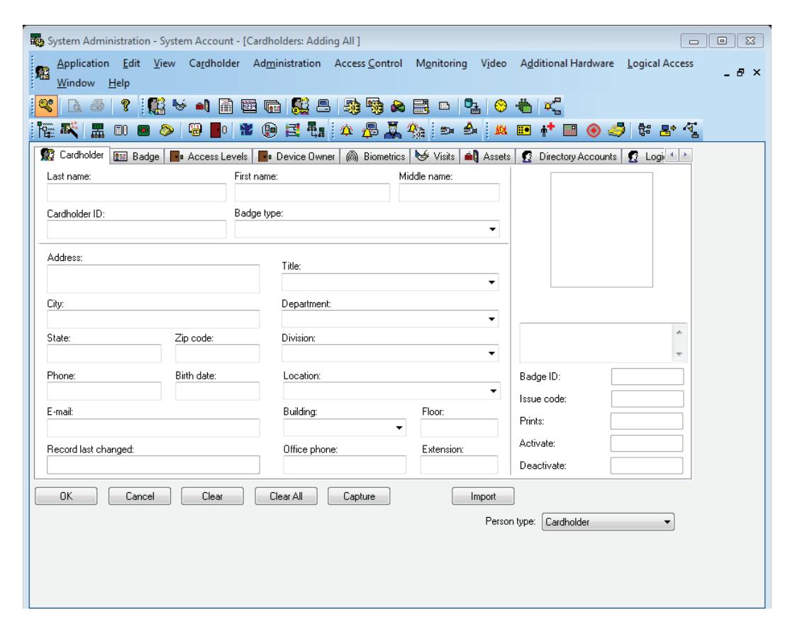
Figure 19 The cardholder general information screen
2 Click Add on the Cardholder tab. Complete all appropriate fields on the form.
3 Click the Badge tab.
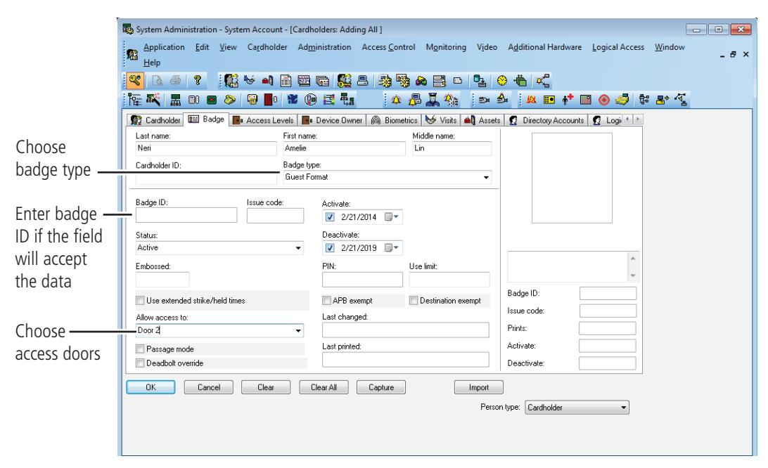
Figure 20 The cardholder, badge information screen
- 4 Select the appropriate Badge Type from the drop-down list.
- 5 Enter a Badge ID for the corresponding badge only if the field will accept data. Sometimes a system is set to automatically generate badge ID's and manual entry will not be required. Complete the rest of Badge tab as required by your organization.
6 Click the Access Level tab.
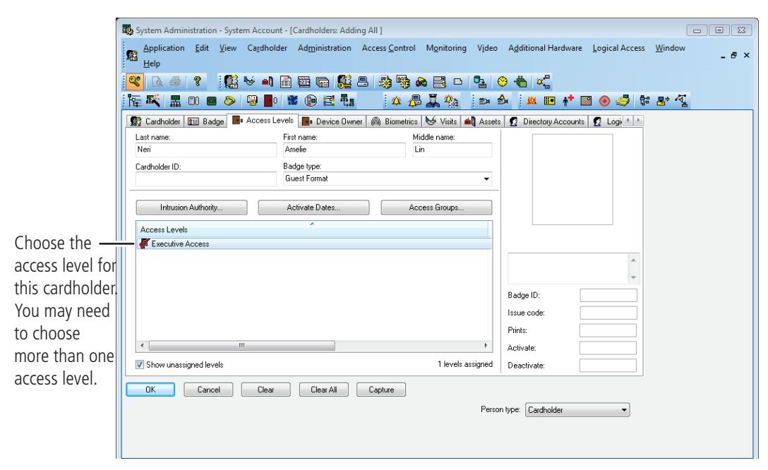
Figure 21 The cardholder, access level information screen
7 Select the appropriate access levels for the cardholder.
Note Only the access levels accompained by a checkmark are selected for assignment.
- 8 Click Ok to save the record.
- 9 Click Encode if you are encoding badge ID's for standard access control.
If the issue is at zero, the following confirmation is displayed
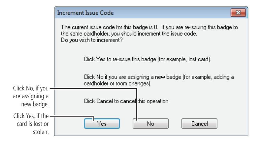
Figure 22 Question regarding the issue code 10 Click No.
The Encode Badge window displays
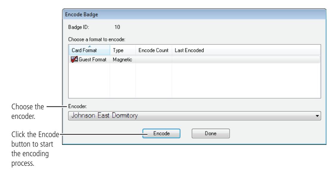
Figure 23 Choosing a card format to encode
11 Make sure that the checkmark is on the card to be encoded, then click Encode.
The encoder is initialized and prompts you to encode the card
12 Slowly swipe the card through the encoder as shown below.

Figure 24 Swiping the magstripe card through the encoder
13 Confirm that the encoding is complete.
B.A.S.I.S. G reader programming is now complete
If you have finished the tasks up to this point, you have completed all steps necessary for the programming of B.A.S.I.S. G functionality or basic functionality for B.A.S.I.S. V. Please see the B.A.S.I.S. System Administration User Guide on the BEST website: www.bestaccess.com for more information on configuring time zones, holidays, access panels, cardholder management and other additional features.
Task 7: Install B.A.S.I.S. Transport
The B.A.S.I.S. Transport software provides communication between your offline locks and your B.A.S.I.S. workstation. With the help of your computer network administrator, if necessary, perform the following steps to set up the B.A.S.I.S. Transport software.
First, confirm that the following requirements are met for running B.A.S.I.S. Transport.
- B.A.S.I.S. System Administration is installed.
- B.A.S.I.S. Communication Server is installed.
B.A.S.I.S. Transport Server (Tray)
The B.A.S.I.S. Transport Tray displays information that is downloaded/uploaded to/from the B.A.S.I.S. Transport database. General use of the Transport Tray Application can be performed by a user with only "User" rights. Perform the following instructions to install B.A.S.I.S. Transport Tray:
- 1 Working on the PC where BASIS is installed stop the communications server.
- 2 Navigate to the BASIS Transport Tray installation folder:
- 3 Right click setup.exe and run as Administrator
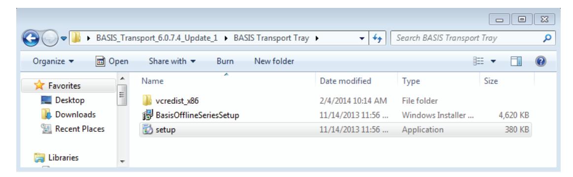
Figure 25 setup.exe
Figure 26 Welcome window
- 4 Click Next.
- 5 The B.A.S.I.S. communication Server service will stop as part of the installation. Deselect the box to automatically start the communication server after installation. The communications server will manually restart after SW installation has been completed.
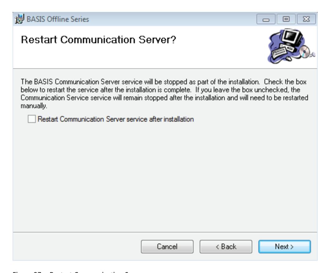
Figure 27 Restart Communication Server
6 Click Next and the Select Installation Folder window will appear.
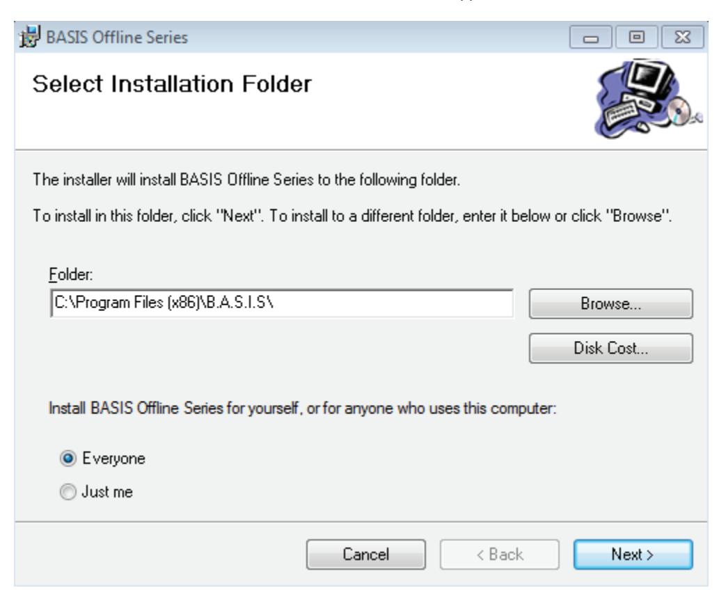
Figure 28 Select Installation Folder
7 The Installation Folder will automatically install on your program file drive, unless you specify otherwise. Make sure to select "Everyone" to enable use of the BASIS Transport Tray application.".
Figure 29 Confirm Installation
Click Next and installation will begin. Once the Installation Complete window pops up, click Close.

Figure 30 Installation Complete
Initial Configuration of Transport Tray
After the B.A.S.I.S. Transport Tray has successfully installed onto your workstation, you will need to set up the location of the SQL Server CE B.A.S.I.S. Transport database file that is used to store offline information. This configuration is required before installing any B.A.S.I.S. Transport software for a PDA or Netbook. Three options exist for the configuration location of the Transport Database location:
- Mobile Device PDA
- Removable Media Device USB Flash Drive
- Known Directory simple directory
Removable Media Device
The Removable Media Device option can be used to store the database if the user has a USB Flash Drive that will be used by the client during reader programming. The flash drive can be inserted into the server's USB port to store the database file. Once a panel download is complete, the device can be removed and inserted into the client computer to allow access to all lock set information during programming activities. History will automatically be uploaded when the device is reconnected to the server and communication server is running If retrieved from the lock. Perform the following steps:
- 1 Go to Start > Programs > Stanley Security Solutions > Stanley B.A.S.I.S. Transport > B.A.S.I.S. Transport Tray menu item.
- 2 The Transport Tray home page will open and an icon is displayed in the task tray.
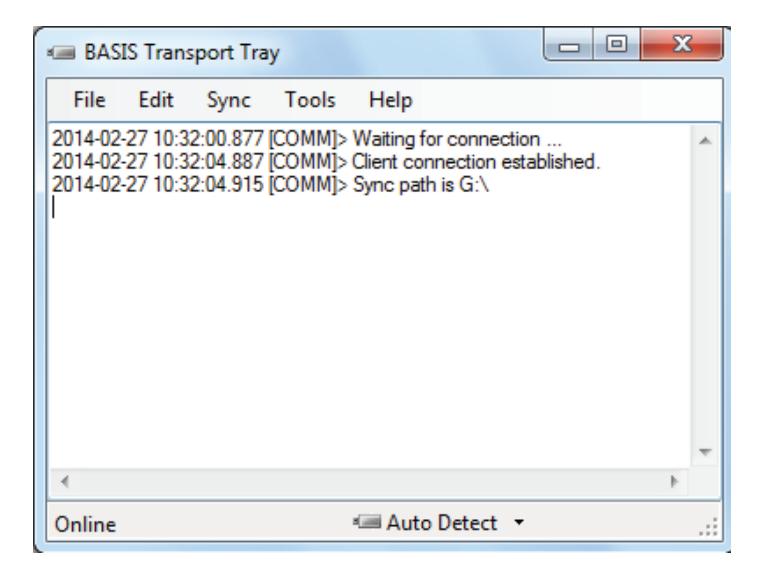
Figure 31 Transport Tray
1 Select"Tools > Configure Removable Media menu item.
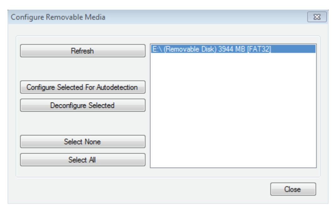
Figure 32 Configure removable media
- 2 Figure 32 will show all available removable devices on the system and the following table provides the definition of each option under the 'Configure Removable Media' window.
- 3 Click the USB flash drive to highlight it.
- 4 Click "Configure Selected For Autodetection" button to configure the USB Flash drive.
| Removable Devices | Definition |
|---|---|
| Refresh | Refreshes the list of removable devices. |
| Configure selected for | Configures the selected media for auto detection. |
| autodetection: |
The B.A.S.I.S.TransportSync.dat and B.A.S.I.S.OfflineSeries.sdf
files are placed on the root drive of the device. |
|
When the device is plugged in and B.A.S.I.S. Communication Server and
the transport tray application are running, history will automatically be uploaded to B.A.S.I.S. |
|
|
A "{DETECTABLE}" string will appear next to the removable device
once configured. |
|
| Deconfigure Selected |
Deconfigures the selected device for auto detection and removes the
_BASISTransportSync.dat file from the device |
| Select None | Select no removable media |
| Select All | Select all removable media |
5 Select Tools > Options. User can select primary transport method.
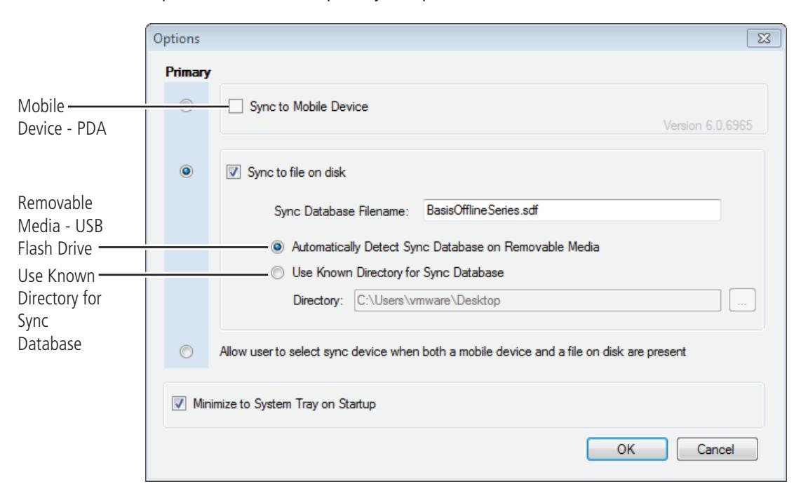
Figure 33 Options
6 Select box to sync to file on disk and check the "Automatically Detect Sync Database on Removable Media" option. This will ensure the application auto detects devices.
Note You are able to select both the "Sync to Mobile Device" and "Sync to file on disk".
7 Click the "OK" button.
Known Directory
If a Removable Media device is not used, a simple directory can be used that is shared on the network. It can also be a shared drive if the client and server are on the same computer. Perform the following steps.
- 1 Go to the B.A.S.I.S. Transport Tray home page.
- 2 Select Tools > Options. The following window will appear.
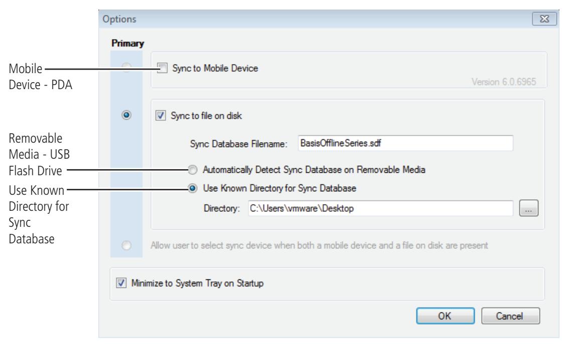
Figure 34 Options
- 3 Select box to sync to file on disk and check the "Use Known Directory for Sync Database" option. Then select the location for the directory. This will ensure the application uses this directory to store the database.
- 4 Click the "OK" button.
Task 8: Installing B.A.S.I.S. Transport for PDA
The Transport PDA application is used to download information to the reader and upload history from the reader to your PDA only. There are three components to the B.A.S.I.S. Transport PDA software that needs installation:
- Microsoft Mobile Device Center or Microsoft ActiveSync program that syncs your workstation to your PDA
- Microsoft.Net Compact 3.5 Framework provides a library of necessary applications that communicates on a mobile device
- Setup.exe B.A.S.I.S. Transport Mobile (PDA) software
Microsoft Mobile Device Center Installation
If you are using Windows 7, please perform the following steps:
- 1 Connect the PDA to the B.A.S.I.S. workstation.
- 2 Download Mobile Device Center from www.microsoft.com and follow the instructions.
- 3 When prompted, set up a partnership with this computer and remove all check marks associated with programs.
- 4 Restart the computer, if needed, after Mobile Device Center completely installs.
- 5 Test the PDA and confirm Mobile Device Center connectivity before proceeding.
- 6 Disconnect PDA from the workstation.
ActiveSync Installation
If you are using Microsoft Windows XP, perform the following steps:
- 1 Connect the PDA to the B.A.S.I.S. workstation.
- 2 Download ActiveSync from www.microsoft.com and follow the instructions.
- 3 When prompted, set up a partnership with this computer and remove ALL check marks associated with programs.
- 4 Restart the computer after ActiveSync completely installs.
- 5 Test the PDA and confirm ActiveSync connectivity before proceeding.
- 6 Disconnect the PDA from the workstation.
Note When ActiveSync is connected, the ActiveSync icon, shown in the task bar on the PC's desktop, is green. When ActiveSync is not connected, the icon is gray.
PDA Software Installation
Now that you have installed Activesync or Mobile Device Center, you can begin to install the B.A.S.I.S. Transport Mobile application.
Note The PDA must be disconnected from the workstation prior to installing B.A.S.I.S. Transport Mobile Software.
1 Navigate to the BASIS Transport Mobile folder. Right click the setup.exe file and run as administrator
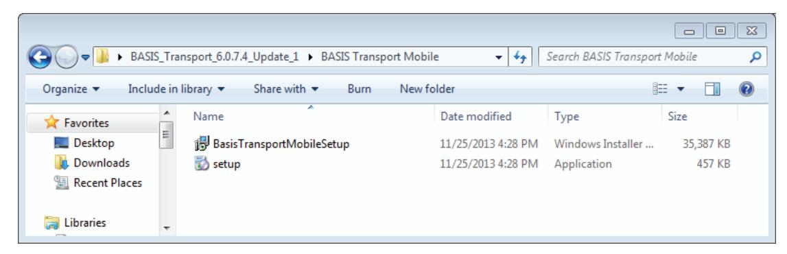
Figure 35 Setup
2 Click Accept.
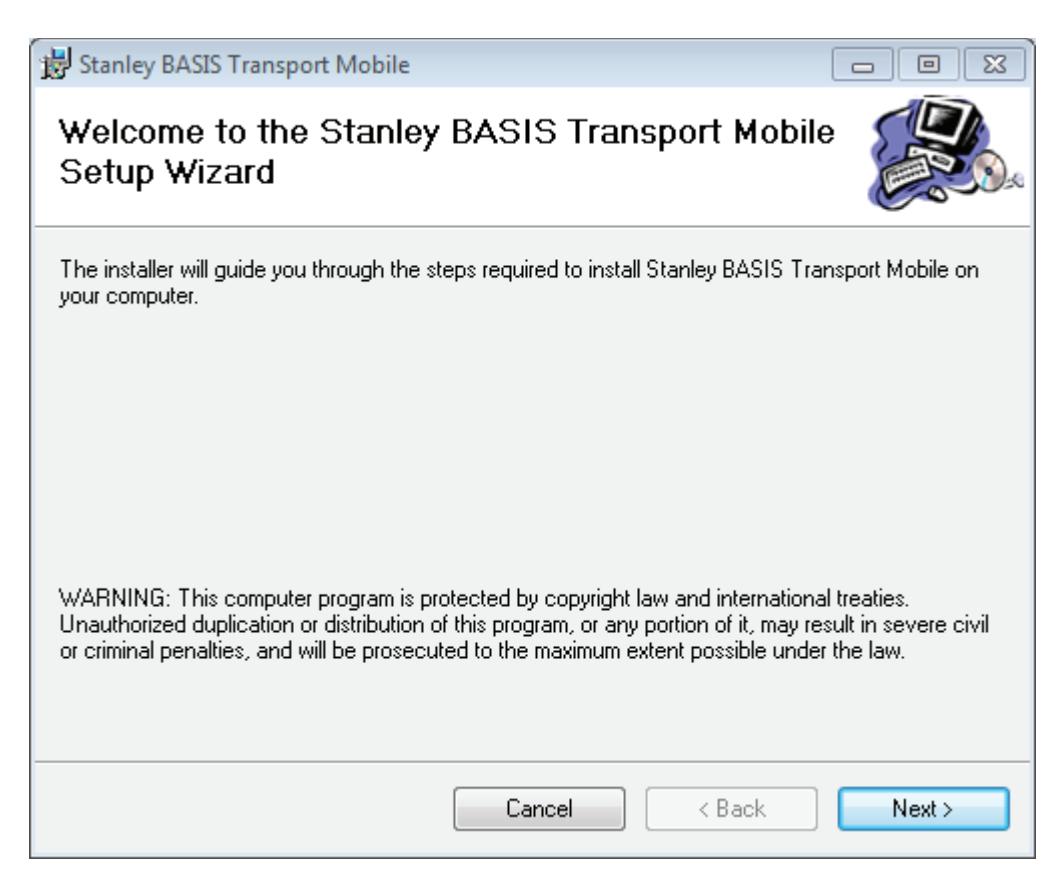
Figure 36 Setup wizard
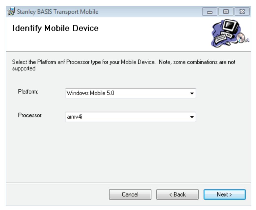
Figure 37 Identify mobile device
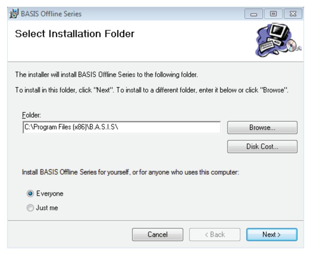
Figure 38 Select installation folder
- 5 The Installation Folder will automatically install on your program file drive, unless you specify otherwise. Select "Everyone" to enable use of the Basis Transport Mobile application.
- 6 Click Next.
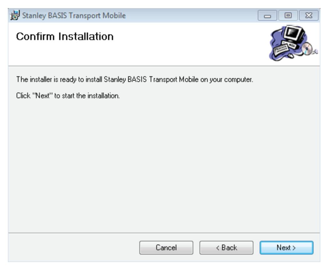
Figure 39 Confirm installation
The Pending Application Install window will appear four (4) times. Click OK each time.
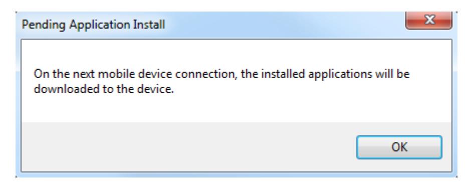
Figure 40 Pending Application Install
- Click OK.
- Power on and connect the PDA to your workstation. Open Windows Mobile Device Center.
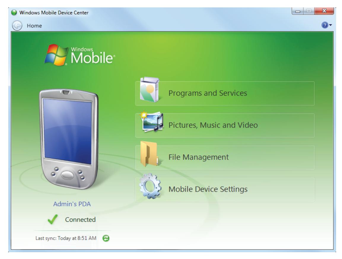
Figure 41 Mobile Device Center
- Choose "Programs and Services"
- Click More.
13 Click "Add/Remove programs".
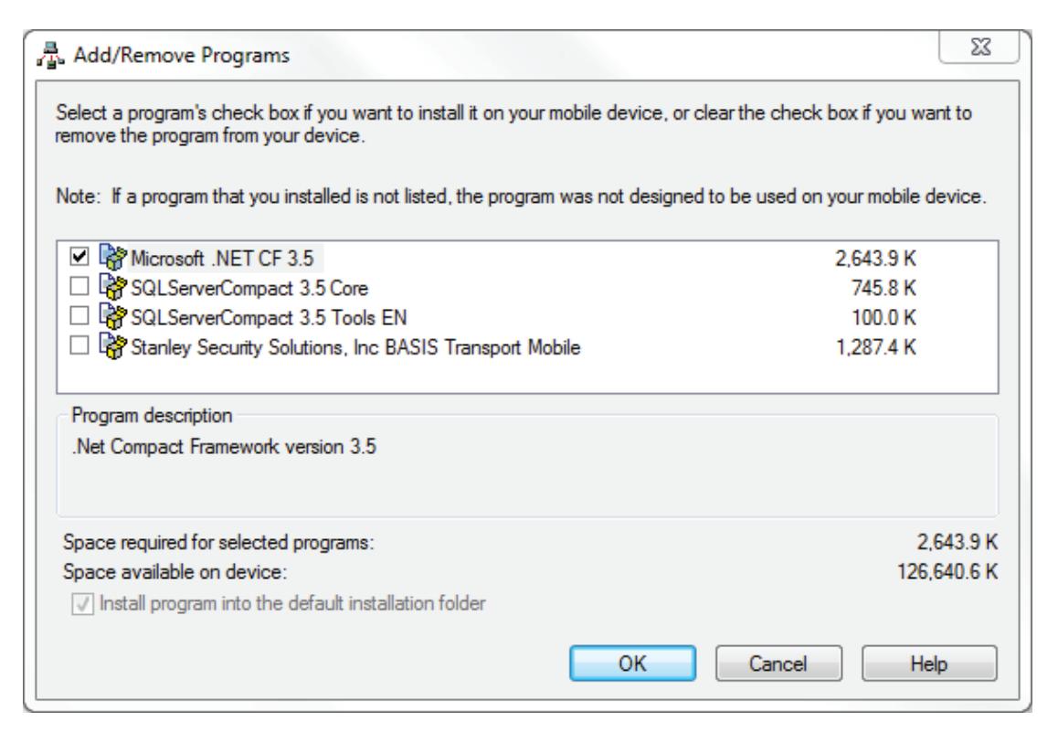
Figure 42 Add/Remove Programs
14 Only click the box for Microsoft .NET CF 3.5 and then Click OK.
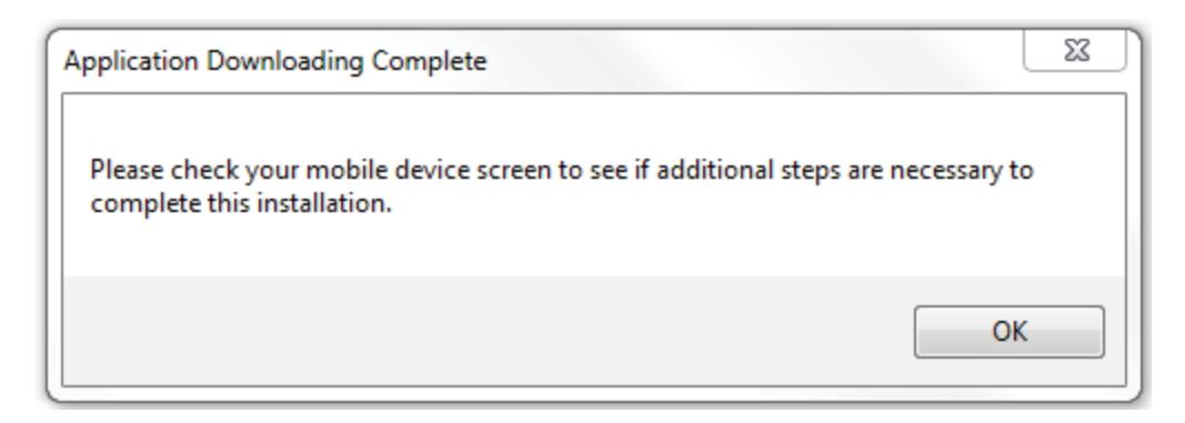
Figure 43 Application Download Complete
Figure 44
15 Upon installation of Microsoft .NET CF 3.5, the following message will appear on your PDA:
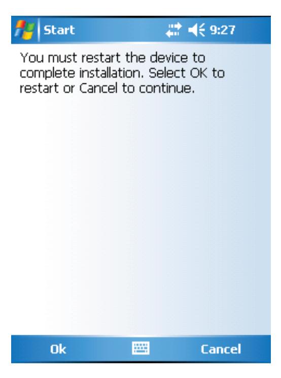
Figure 45 Restart Device
- 16 Click OK on the PDA and wait while the device reboots and reconnects to Windows Mobile Device Center or Activesync.
- 17 Once the PDA reconnects, open Windows Mobile Device or Activesync and choose "Programs and Services".
- 18 Click More
19 Click "Add/Remove Programs".

Figure 46 Add/Remove Programs
- 20 Click the check box for each of the following:
- Microsoft .NET CF 3.5
- SQL ServerCompact 3.5 Core
- SQL ServerCompact3.5 Tools EN
- Stanley Security Solutions, Inc BASIS Transport Mobile
21 Click OK.
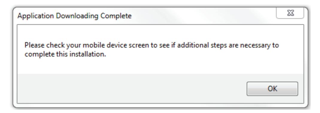
Figure 47 Application Downloading Complete 22 Click OK and check the PDA for any prompts.
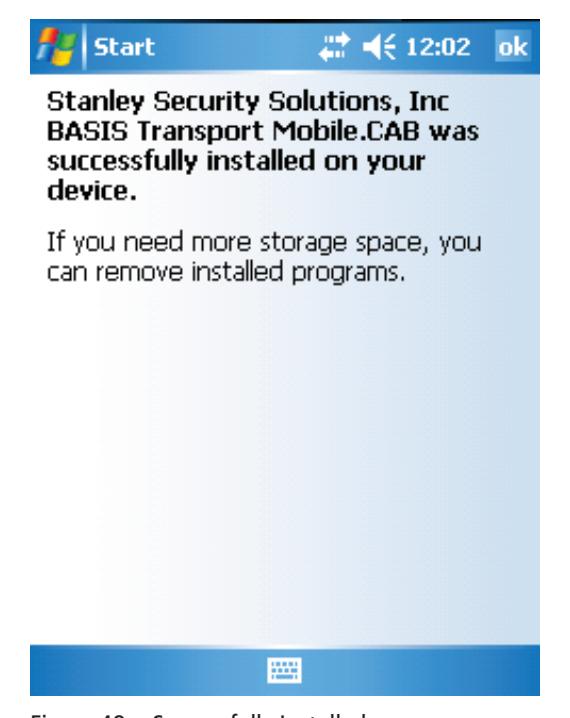
Figure 48 Successfully Installed
Task 8: Install B.A.S.I.S. Transport for Netbook/Notebook
The B.A.S.I.S. Transport application is used to download information to the reader and upload history from the reader to your Netbook/Notebook only. There are two components to the B.A.S.I.S. Transport Client software that needs to be installed:
- SQL Server 3.5 Compact relational database for applications that run on mobile devices and desktops
- Setup.exe B.A.S.I.S. Transport Client (Netbook/Notebook) softwar e
B.A.S.I.S. Transport Installation
To install B.A.S.I.S. Transport software, complete the following steps:
- 1 Navigate to the BASIS Transport folder.
- 2 Right click setup.exe and Run as administrator.
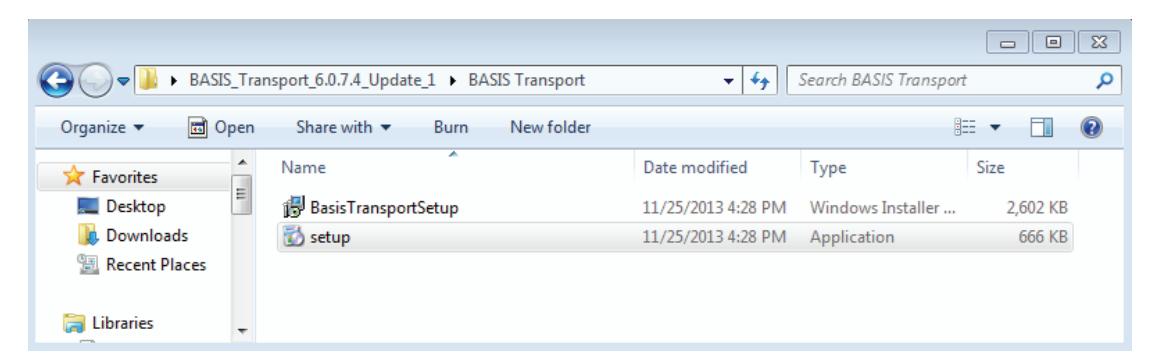
Figure 49 Setup
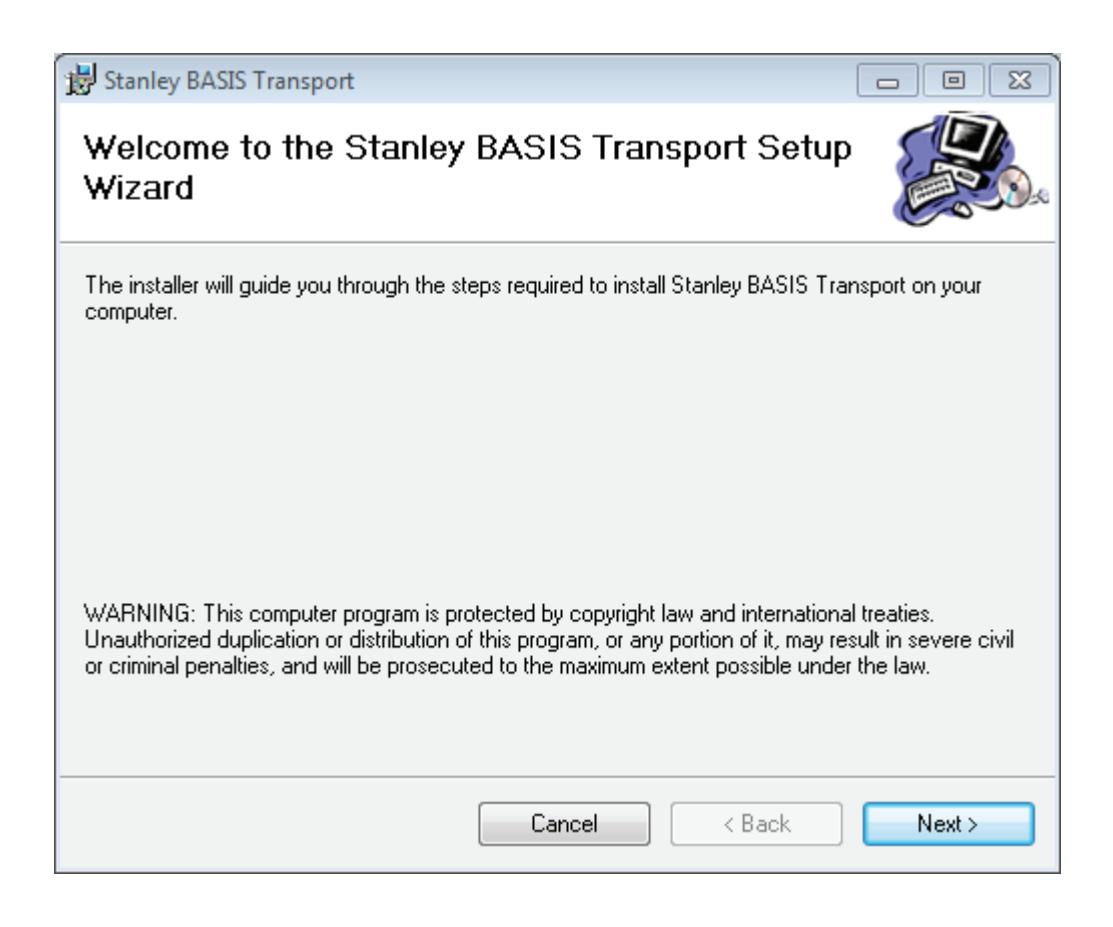
Figure 50 Setup Wizard
3 Click Next and the Select Installation Folder window will appear.
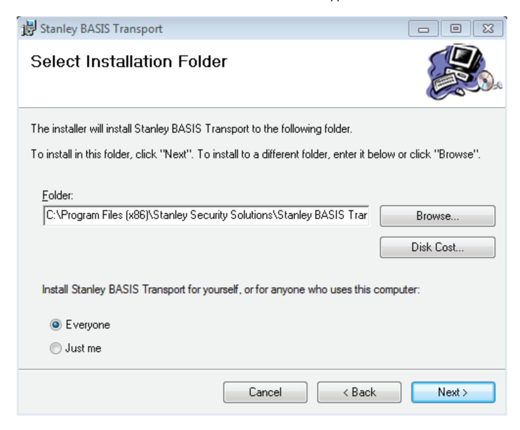
Figure 51 Select installation folder
4 The Installation Folder will automatically install on your program file drive, unless you specify otherwise. Make sure to select "Everyone" to enable use of the BASIS Transport application.
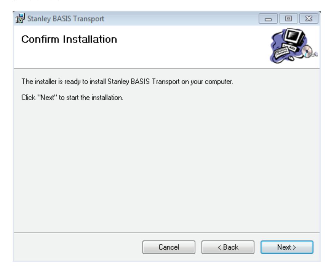
Figure 52 Confirm installation
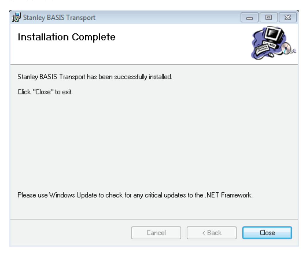
Figure 53 Installation complete
7 Click Close
3 Set Up and Maintain Offline Locks
This section describes how to use your B.A.S.I.S.® Transport software. The following topics are covered:
- Transferring reader configurations from B.A.S.I.S. System
- Administration to your PDA or Netbook/Notebook
- Connecting the PDA or Netbook/Notebook to the Lock
- Manually Changing the PIN in a Dual Validation Lock
Transferring Lock/Reader Configurations
At this point you have successfully completed the following for the B.A.S.I.S. Offline System:
- Task 1: Install B.A.S.I.S. Software See page 15.
- Task 2: Install Encoder See page 15.
- Task 3: Define Card Formats See page 19.
- Task 4: Define Badge Types See page 22 .
- Task 5: Define Offline Access Panels See page 25 .
- Task 6: Define Guest Locks/Readers See page 27 .
- Task 7: Install B.A.S.I.S. Transport See page 38 .
- Task 8: Install B.A.S.I.S. Transport on PDA or Netbook/Notebook See page 48 or page 60 .
Now that you have installed and defined the B.A.S.I.S. Offline System, you'll want to transfer your new configurations or changes to your locks/readers, using your PDA or Netbook/Notebook. Two steps are involved to complete the transfer:
- Workstation connection
- Connecting your PDA to your workstation through a USB port
- or Insert a USB flash drive into your workstation to transfer configurations to Netbook/Notebook
- Connecting your PDA or Netbook/Notebook to reader
Set Up and Maintain 66
Transferring Lock/Reader Configurations to the PDA
To transfer lock/reader configuration made through the B.A.S.I.S. System Administration on your workstation to your PDA, perform the following steps:
1 Connect your PDA to your workstation through a USB Port.
Note If using a PDA, make sure B.A.S.I.S. Transport is not running.
2 Make sure that a connection has been made between Mobile Device Center and your PDA.
Note To download Mobile Device Center, please see www.microsoft.com
Connecting the PDA to the Lock/Reader
To begin transferring configurations from your PDA to your lock, you must first properly connect the PDA to the lock/reader. See Figure 54 and perform the following steps:
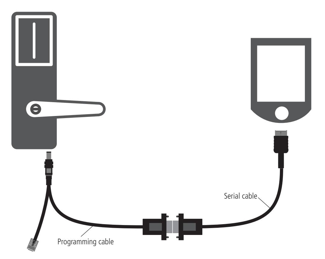
Figure 54 Connecting the PDA to a lock
- 1 Connect the serial cable to the PDA.
- 2 Connect the serial cable to the programming cable.
- 3 Connect the programming cable to the lock's communication port. The connector snaps into place.
- 67 Set Up and Maintain
Opening Configurations on the PDA
After connecting the PDA to the lock, you must open the Mobile Transport Application on the PDA to transfer all of your configurations. Perform the following steps:
1 On the PDA, tap Start > Programs > BA_TransportMobile:
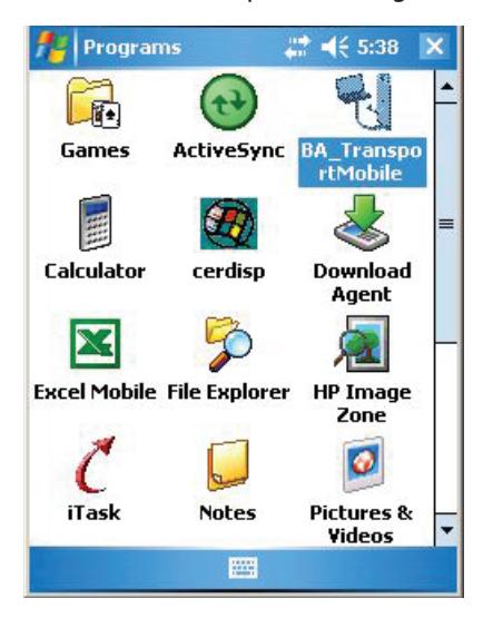
Figure 55 BA_TransportMobile
2 On the Transport Mobile home page, tap Menu > Open
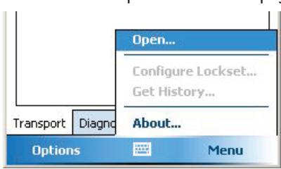
Figure 56 Open...
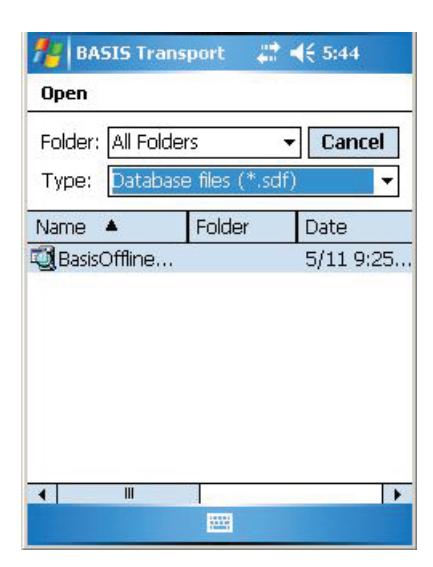
Figure 57 Open folder
3 Tap the BasisOfflineSeries.sdf file and the screen should refresh to reflect your selection. The lock is now configured to your panel/reader:
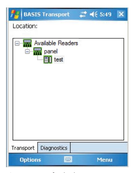
Figure 58 Refreshed screen
Setting the Max Baud Rate:
1 Set the Max Baud Rate to 38400 by tapping the Options button at the bottom of the screen.
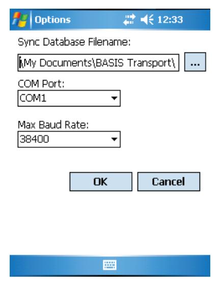
Figure 59 Max Baud Rate
2 Once you have selected the correct sync path to your sdf file and configured the Max Baud Rate to 38400, Click OK.
Configure Lockset
Perform the following steps to configure your lock:
1 While the Transport tab is selected, tap the lock/reader to be programmed.

Figure 60 Reader selected
2 Tap Menu and tap Configure Lockset...

Figure 61 Menu
Note The password for a lock is the password programmed in the virtual access control panel. You must enter the password exactly as it was entered in the Password field on the Offline lock tab in the Access Panels screen. Capitalization must be the same. If this is the initial time the lock is being programmed or if the lock was reset to its factory default setting, leave the password field blank and tap OK.
3 The following screen will appear:
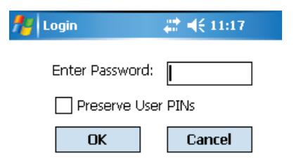
Figure 62 Enter password
Note During initial programming of a lock you will see a warning "Passwords do not match continue anyway?" Click OK to continue configuring the lock
4 If you have a Dual Validation Lock (with keypad) and you wish to preserve pins at the reader during the configuration, select the "Preserve User PINs". Or, to reprogram the lock with the PINs stored in B.A.S.I.S., remove the check from the Preserve user pins check box.
Warning: If users have reprogrammed their PINs at the lock and you do not preserve the user PINs, users will no longer be able to access the lock. The ability to program PIN's is only available when using Card and PIN mode.
- 5 Enter password and Click OK.
- 6 The following screen should appear:
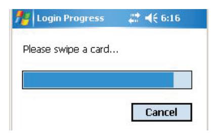
Figure 63 Swipe card
7 Swipe a magnetic stripe card or proximity card through the reader. This will wake the lock to start the connection.
8 The Transport screen will show that it is currently downloading. Once the download is successful, the following screen will appear:
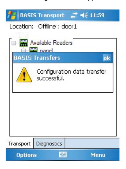
Figure 64 Configuration data transfer successful
Get History
Perform the following steps to retrieve history events from the lock:
1 While the Transport tab is selected, tap the lock/reader history to be retrieved.
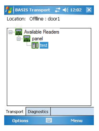
Figure 65 Reader selected
2 Tap Menu and tap Get HIstory...
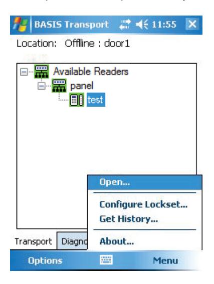
Figure 66 Menu
Note The password for a lock is the password programmed in the virtual access control panel. You must enter the password exactly as it was entered in the Password field on the Offline lock tab in the Access Panels screen. Capitalization must be the same. If this is the initial time the lock is being programmed or if the lock was reset to its factory default setting, leave the password field blank and tap OK.
3 Enter password and Click OK.
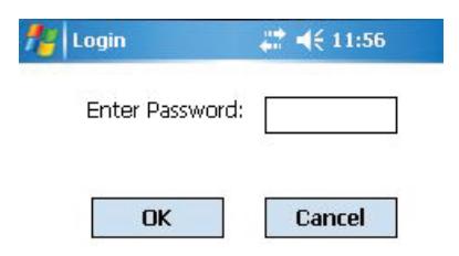
Figure 67 Enter password
4 The following screen should appear:

Figure 68 Swipe card
- 5 Swipe a magnetic stripe card or proximity card through the reader. This will wake the lock to start the connection.
- 6 The Transport screen will show that it is currently downloading. Once the download is successful, the following screen will appear:
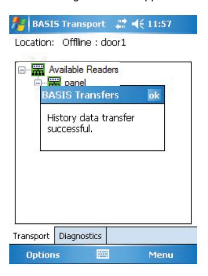
Figure 69 History date transfer successful
Diagnostics
The Diagnostics option on your PDA allows you to view information about the reader and configure options for your lock/reader. The options include:
- Connect/Disconnect
- Set: Date/Time/DST enable, Reader Technology (Proximity, Magnetic, Dual Validation), and Online Mode
- Reset: Diagnostics Code/Use Count
- Unlock Once
- Deep Reset
- Download Firmware
Note: Some of the diagnostic options are only available if the B.A.S.I.S. G or V lock is using a UVC board. If you are using a legacy B.A.S.I.S. G or V lock, unsupported options will be grayed out.
Connect
To connect to a reader using Transport, perform the following steps:
1 From the home page of B.A.S.I.S. Transport Mobile, tap on the Diagnostics tab. Tap menu and the following choices will pop up:
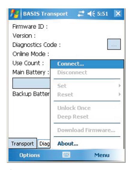
Figure 70 Connect...
2 Tap Connect...
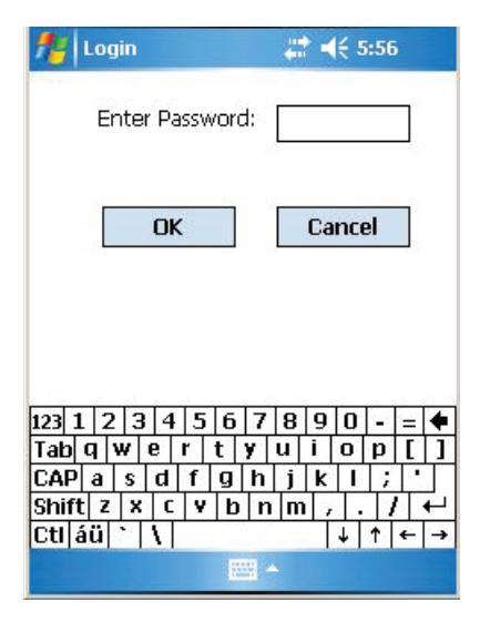
Figure 71 Login
3 Enter your password.
Note The password for a lock is the password programmed in the virtual access control panel. You must enter the password exactly as it was entered in the Password field on the Offline lock tab in the Access Panels screen. Capitalization must be the same. If this is the initial time the lock is being programmed or if the lock was reset to its factory default setting, leave the password field blank and tap OK.
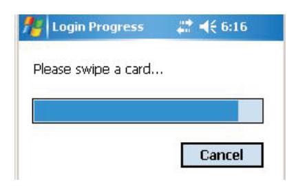
Figure 72 Please swipe card
4 Swipe a magnetic stripe card or proximity card through the reader. This will wake the lock to start the connection.
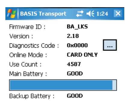
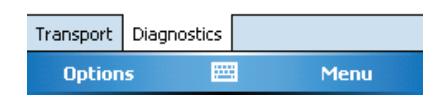
Figure 73 Connection successful
5 The screen above shows the successful connection to the PDA.
The table below gives a definition for all of the fields in the Diagnostics window:
| This Field | Shows |
|---|---|
| Firmware ID | ID indicating the type of firmware in the lock. |
| Technical support personnel may ask you to | |
| provide this information. | |
| Version | Version number of the lock's firmware. Technical |
| support personnel may ask you to provide this | |
| information. | |
| Diagnostics Code | Hexadecimal number indicating firmware |
| conditions, such as firmware resets, that have | |
| occurred at the lock since the diagnostics code | |
| was last cleared. The code 0x00 means no | |
| conditions have occurred. | |
| To view the meaning of the code, click/tap the | |
| more button (). The Diagnostics Code window | |
| shows each active diagnostics code and its | |
| meaning. Click/tap the close button (X) to close | |
| the window. | |
| Online Mode | Whether the lock is under time zone control |
| (Automatic) or set to a specific mode, such as | |
| Locked or Unlocked. For more information, see | |
| "Set: Online Mode" on page 82. | |
| Use Count | Number of times access was granted since the |
| use count was last reset. To reset the use count, | |
| see "Reset: Use Count" on page 85. | |
| Main Battery | Current power level of the lock's battery pack. |
| No shading in the status bar indicates an Alarm | |
| condition. The batteries are dead and must be | |
| replaced. If the shading falls within the Warning | |
| range, the power level is 30% or lower. You | |
| should replace the batteries soon. If the shading | |
| falls within the Good range, the power level is | |
| between 30% and 100%. | |
| Backup Battery | Current power level of the lock's coin cell |
| battery, used to back up the lock's memory if | |
| the main battery pack dies or is disconnected. | |
| If the backup battery is Bad, you should replace | |
| it. Refer to the B.A.S.I.S. G Service Manual or the | |
| B.A.S.I.S. V Service Manual on | |
| www.bestaccess.com. |
Set Up and Maintain 78
Disconnect
Note The following diagnostic functions are performed while the PDA is already connected to the lock and the Diagnostics tab is selected.
1 To Disconnect, tap Menu and then tap disconnect.
Set
You have three options under the Set menu:
- Date/Time/DST enable
- Reader Technology
- Online Mode
Set: Date/Time/DST Enable
Warning This feature should only be used to set time on controllers in a time zone that observes Daylight Savings. For readers in time zones that do not observe Daylight Savings, you will need to run Configure Lockset command on the lock to update time.
To set Day/Time to the current time, perform the following steps:
1 Tap Menu Set Date/Time.
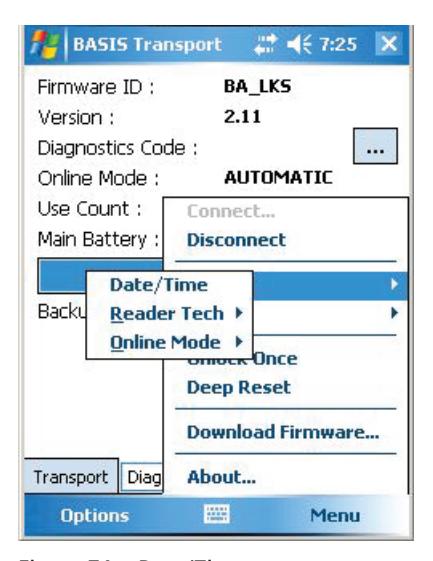
Figure 74 Date/Time
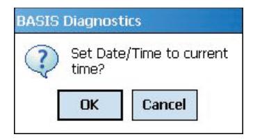
Figure 75 Set Date/Time?
2 Click OK.
Set: Reader Technology
To set which reader technology the lock/reader is using, perform the following steps:
1 Tap Menu > Set
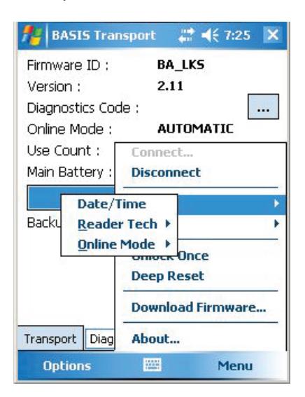
Figure 76 Set Reader Tech
2 Tap Reader Tech.
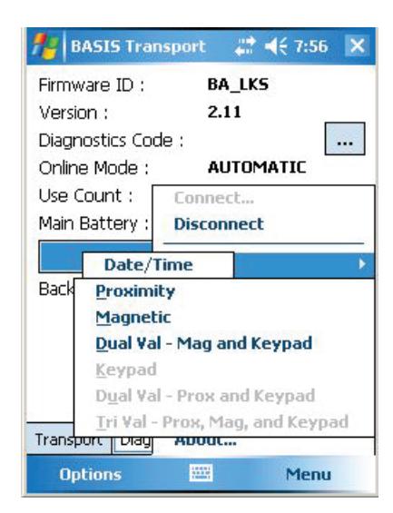
Figure 77 Set Reader Tech
Select your reader technology.
Set: Online Mode
A B.A.S.I.S. offline lock mode of operation is determined by its programming. The diagnostics information for the lock indicates the locks current Online Mode setting.
For example, during an emergency you might set a lock's online mode to Unlocked so that emergency personnel can access the room. When the event is over, you must return the lock to its original online mode setting to resume normal operation.
The online mode will change only after disconnecting from the lock.
The following online modes are available:
- Automatic The lock is under time zone control.
- Card Any valid card in the lock's database can access the lock.
- Card and PIN Any valid card and PIN combination programmed in the lock's database can access the lock.
- Card or PIN Any valid card or PIN programmed in the lock's database can access the lock.
- Facility Code Any card with a valid facility code can access the lock.
- Locked The door is locked. All cards and PINs are denied access.
- Unlocked The door is unlocked.
To override the current online mode of the reader, perform the following steps:
1 Tap Menu > Set > Online Mode.
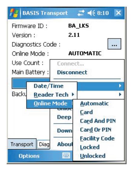
Figure 78 Online Mode options
Reset
You have two options under the Set menu:
- Diagnostics Code
- Use Count
Reset: Diagnostics Code
Diagnostic codes are used to help identify issues with the lock, such as low battery alarms that might have occurred since the diagnostics code was last cleared. To reset diagnostic codes, perform the following steps:
1 Tap Menu > Reset > Diagnostics Code.
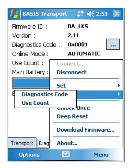
Figure 79 Diagnostics Code
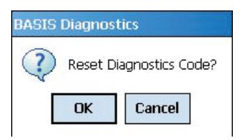
Figure 80 Reset Diagnostics Code?
2 Click OK and the code will be reset to 0x0000.
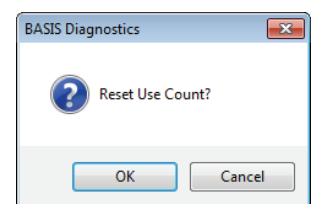
Reset: Use Count
Every B.A.S.I.S. offline reader counts the number of times access has been granted to a card or pin since the use count was last reset. You can use this count to track how often a lock is accessed over time. To reset the Use Count, perform the following steps:
1 Tap Menu > Reset > Diagnostics Code.
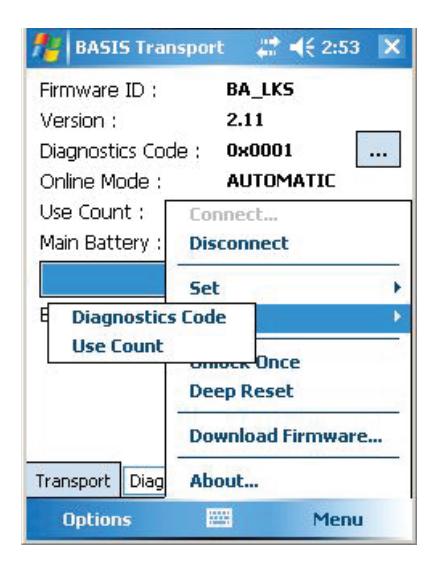
Figure 81 Diagnostics Code
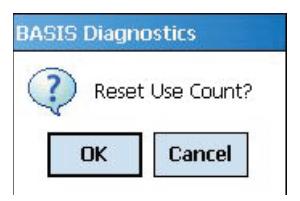
Figure 82 Reset Use Count?
2 Click OK and the count will be reset to 0.
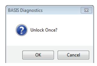
Unlock Once
You can use the PDA to unlock a door for the locks/readers unlock duration. This feature is useful when you need to access the inside of the door to replace the lock's batteries or perform other maintenance for the lock. Perform the following steps:
1 Tap Menu > Unlock Once.
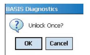
Figure 83 Unlock Once
2 Click OK if you wish to unlock momentarily.
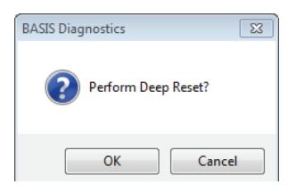
Deep Reset
To reset the lock/reader to factory settings, perform the following steps:
1 Tap Menu > Deep Reset
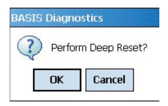
Figure 84 Deep Reset.
2 Click OK to Deep Reset
Download Firmware
To download firmware updates to the lock from your PDA, perform the following steps:
Note A firmware download is only available if the lock is fitted with the UVC board.
1 Tap Menu > Download Firmware.
Note Firmware files are available by contacting Stanley Security Technical Support at (800) 392-5209.
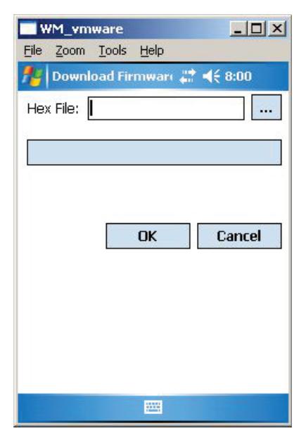
Figure 85 Download Firmware
2 Click on to browse for your firmware hex file and Click OK to download firmware.
Transferring Lock/Reader Configurations to the Netbook/Notebook
To transfer lock/reader configuration made through the B.A.S.I.S. System Administration to your Netbook/ Notebook, perform the following steps:
Note The following presumes the user has successfully logged into Basis System Administration and the communication server is running. It is also presumed the USB to serial cable is connected and configured on the Netbook per the manufacturers instructions.
- 1 Connect a USB flash drive in the a USB port on your Netbook/Notebook and then open B.A.S.I.S. Transport Tray.
- 2 In System Administration and working from the System Tree right click the reader to be programmed, and select Download.
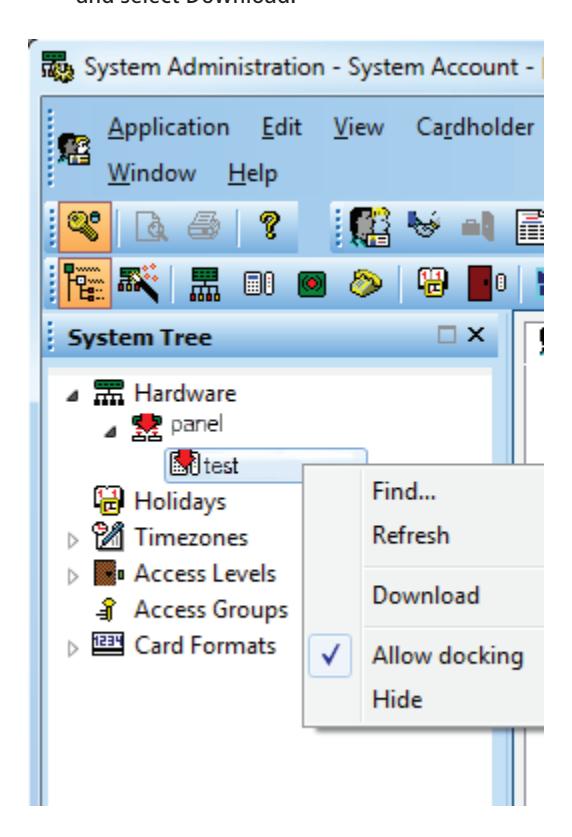
Figure 86 Reader Program Download
Click OK.
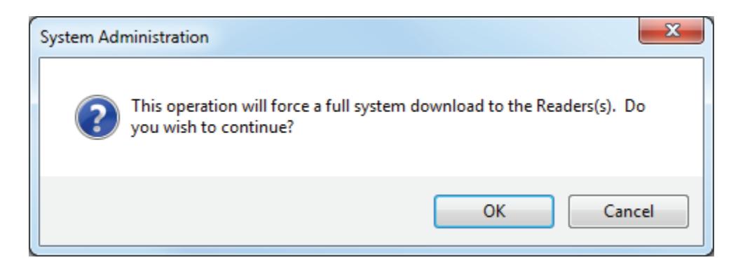
Figure 87 Full System Download
- Upon Sync successfully completed, eject and disconnect the USB flash drive from your workstation.
- Connect the USB flash drive to the USB/com port on your Netbook/Notebook and connect the USB to serial cable.
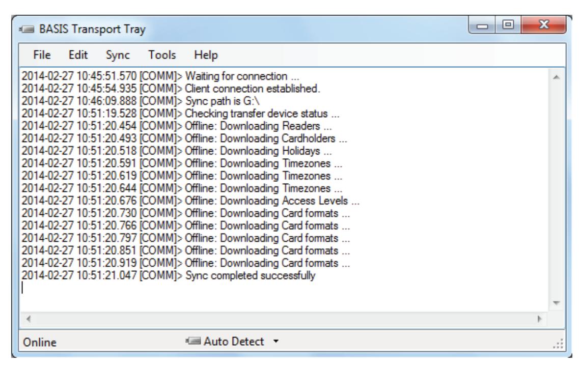
Figure 88 Transfer Completed
Open the Basis Transport application.
Opening a Panel/Reader Configuration on a Netbook
After saving the BasisOfflineSeries.sdf file on your Netbook/Notebook from your USB flash drive, you'll need to upload all of your B.A.S.I.S. System Administration configurations to Transport Client. Perform the following steps:
- 1 Go to the B.A.S.I.S. Transport home page by selecting Programs > Stanley Security Solutions > Stanley BASIS Transport > BASIS Transport.
- 2 Go to the File > Open…" menu item. The following window will appear.
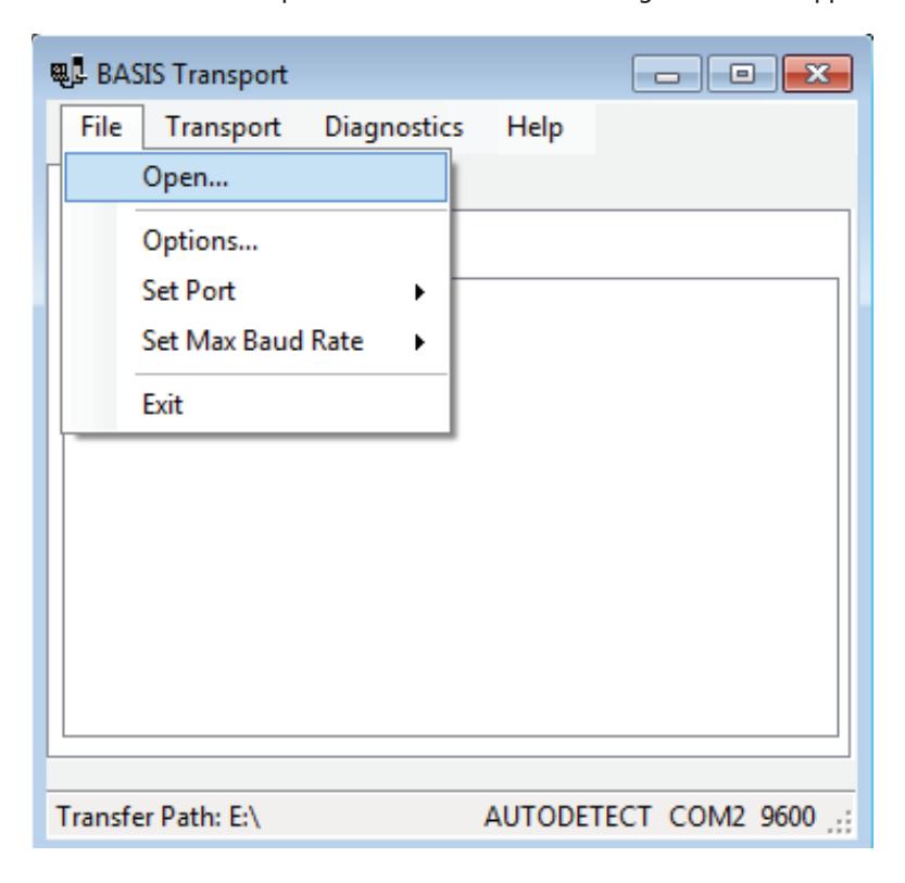
Figure 89 Open file
3 Select your BasisOfflineSeries.sdf file and Click Open.
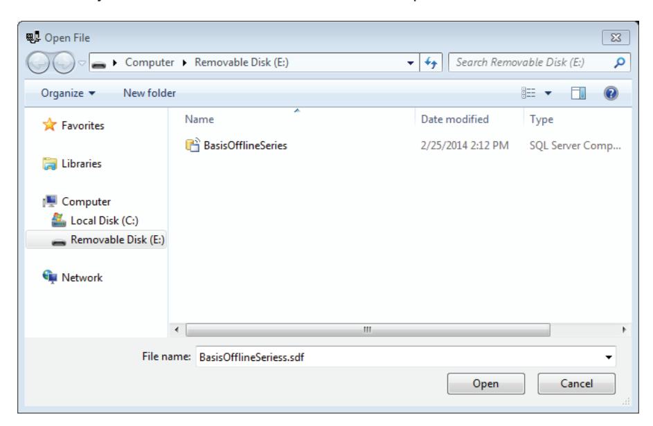
Figure 90 Open file
4 The main window will refresh with the list of locks/readers.
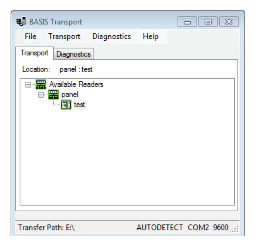
Figure 91 List of locks/readers
Setting the USB/Communication Port
Once your panel has refreshed to reflect your BasisOfflineSeries.sdf , you must make sure that the correct com port is selected to continue with configuration. Perform the following steps:
1 On the Transport home page, select File > Set Port > COM (port that is being used by the lock/reader). In this example, it is COM2.
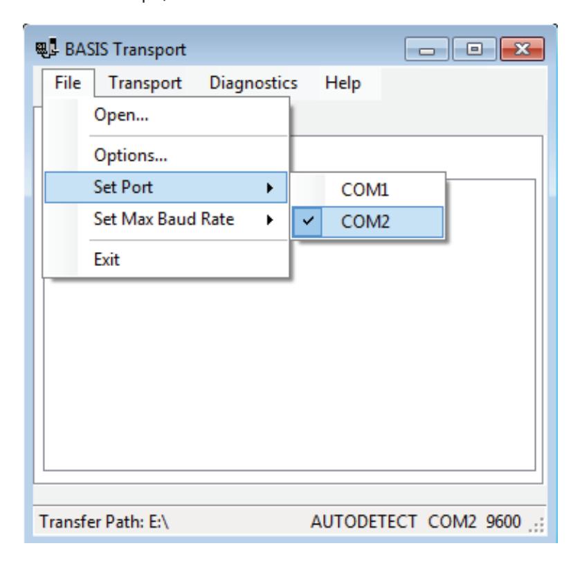
Figure 92 Set port
On the Transport home page, select File > Set Max Baud Rate > In this example, it is 38400.
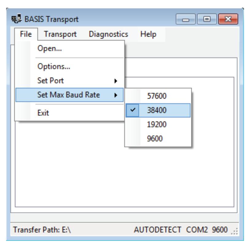
Figure 93 Set Max Baud Rate
Connecting the Netbook/Notebook to the Reader
To begin transferring configurations from your Netbook/Notebook to your lock, you must first properly connect the Netbook/Notebook to the reader. See Figure 94 and perform the following steps:
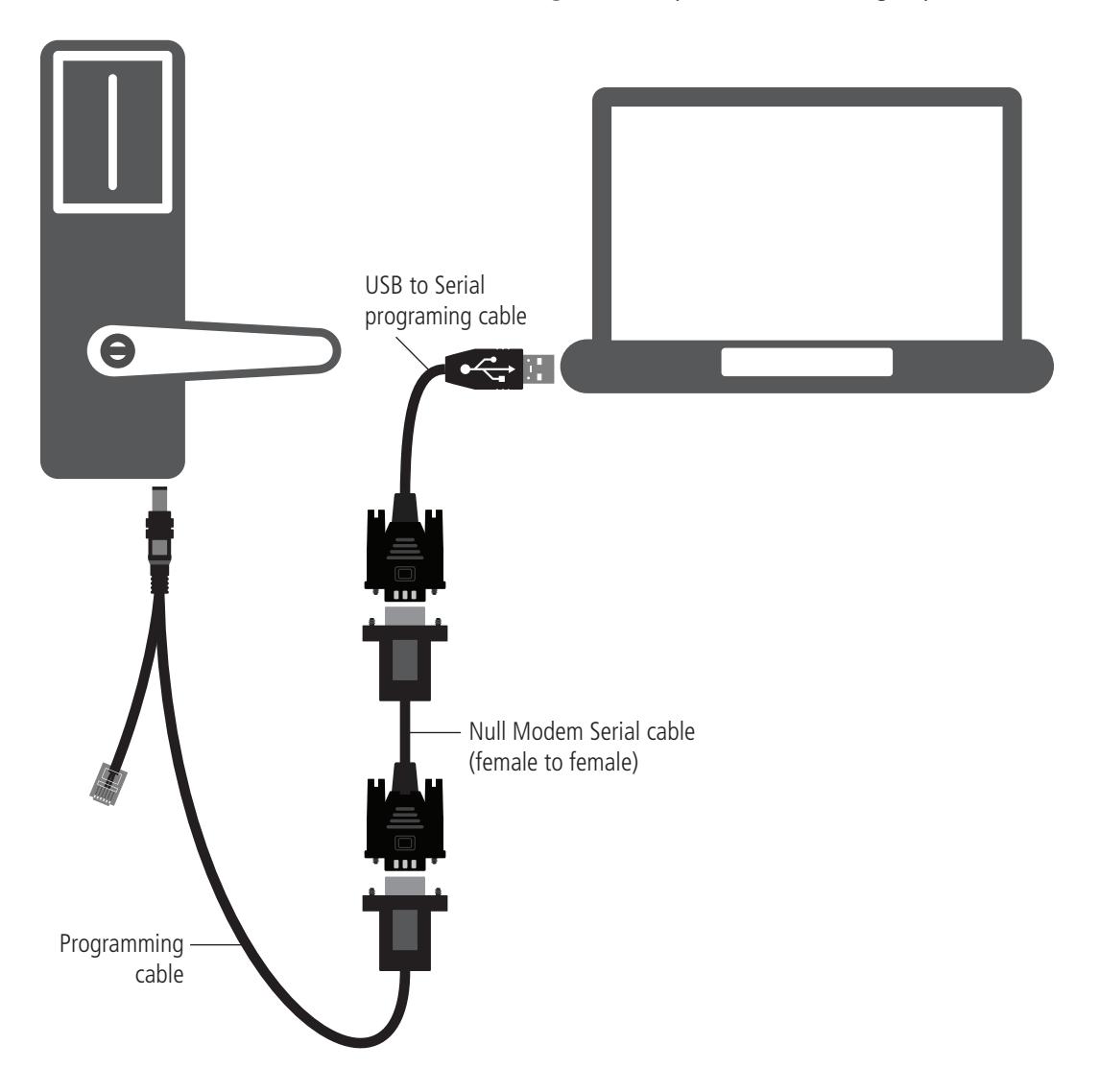
Figure 94 Connecting the Netbook/Notebook to a lock
- 1 Connect the USB to Serial Programming cable to the USB port on your Netbook/Notebook.
- 2 Connect the USB to Serial Programming cable to the Null Modem Serial cable (female to female).
- 3 Connect the Null Modem Serial cable (female to female) to the Programming cable.
- 4 Connect the Programming cable to the lock's Communication port. The connector snaps into place.
Note: Length of cables displayed in Figure 51 may be longer than illustrated.
Set Up and Maintain 94
Configure Lockset
The configure lockset option will allow you to configure a reader based on any configuration in B.A.S.I.S. System Administration. Perform the following steps:
Note: If this is the initial installation of the lock, you will need to run diagnostics first and set the Use Count to 0. See "Reset: Use Count" on page 85 .
1 Return to the B.A.S.I.S. Transport home page with the Transport tab selected and the list of locks/ readers present.
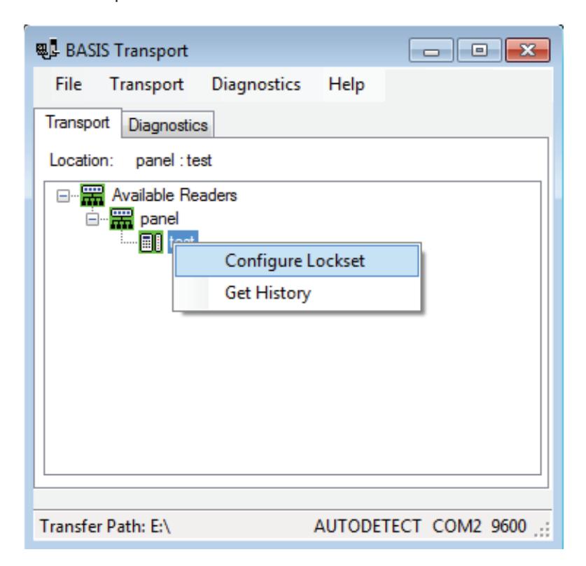
Figure 95 Configure lockset
2 Right-click on the desired reader configuration and select Configure Lockset. The following window will appear:
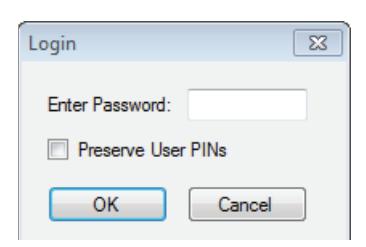
Figure 96 Enter password
Note The password for a lock is the password programmed in the virtual access control panel. You must enter the password exactly as it was entered in the Password field on the Offline lock tab in the Access Panels screen since it is case sensitive. If this is the initial time the lock is being programmed or if the lock was reset to its factory default setting, leave the password field blank and tap OK.
3 Enter the password and press the OK button. If you have a Dual Validation Lock (with keypad) and you wish to preserve pins at the reader during the configuration, select the "Preserve User PINs". Or, to reprogram the lock with the PINs stored in B.A.S.I.S., remove the check from the Preserve user pins check box.
Warning If users have reprogrammed their PINs at the lock and you do not preserve the user PINs, users will no longer be able to access the lock. The ability to program PIN's is only available when using Card and PIN mode.
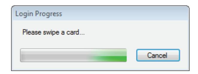
Figure 97 Login process
- 4 Swipe a magnetic stripe card or proximity card through the reader. This will establish communications and begin the programming process. The following window may appear if this is the initial time the lock is programmed or if the lock has been reset to factory settings.
- 5 Click Yes.
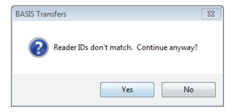
Figure 98 B.A.S.I.S. transfers
6 A window shows the download progress. Once the download is complete, the following window will appear.
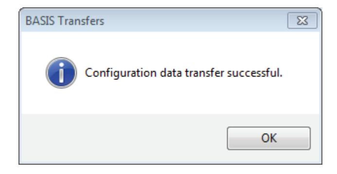
Figure 99 Configuration successful
7 Click OK and the following window will appear.
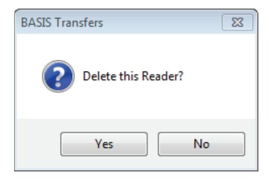
Figure 100 Delete reader
8 If you wish to delete the reader from the list of readers, click the "Yes" button (recommended). Otherwise press the "No" button.
9 This completes the reader configuration.
Get History
The Get History option allows you to upload history from the lock.
1 Return to the B.A.S.I.S. Transport home page with the Transport tab selected.
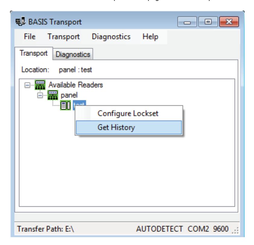
Figure 101 Get history
2 Right-click on the desired reader configuration and select Get History. The following window will appear.
Note The password for a lock is the password programmed in the virtual access control panel. You must enter the password exactly as it was entered in the Password field on the Offline lock tab in the Access Panels screen since it is case sensitive. If this is the initial time the lock is being programmed or if the lock was reset to its factory default setting, leave the password field blank and tap OK.
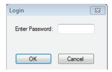
Figure 102 Login
3 Enter the reader password and press the OK button.
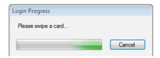
Figure 103 Swipe card
4 Swipe a magnetic stripe card or proximity card through the reader. This will establish communication and retrieve history events from the lock. A window shows the history upload progress. Once the upload is complete, the following window will appear.
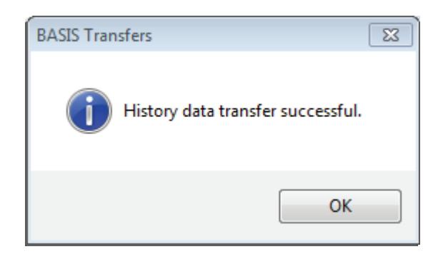
Figure 104 History data transfer successful
5 Click OK to exit.
Diagnostics
The Diagnostics view allows you to view information about the reader and configure options for your reader. The options include:
- Connect/Disconnect
- Set: Date/Time/DST enable, Reader Technology (Proximity, Magnetic, Dual Validation), and Online Mode
- Reset: Diagnostics Code/Use Count
- Unlock Once
- Deep Reset
- Download Firmware
Note: Some of the diagnostic options are only available if the B.A.S.I.S. G or V lock is using a UVC board. If you are using a legacy B.A.S.I.S. G or V lock, the options will appear gray and unable to program.
Connect
To connect to your reader through Transport, perform the following steps:
1 Go to Diagnostics > Connect.
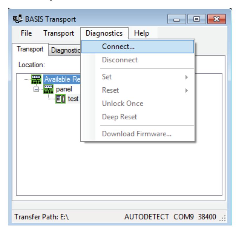
Figure 105 Diagnostic connect
Note The password for a lock is the password programmed in the virtual access control panel. You must enter the password exactly as it was entered in the Password field on the Offline lock tab in the Access Panels screen. The password is case sensitive. If this is the initial time the lock is being programmed or if the lock was reset to its factory default setting, leave the password field blank and tap OK.
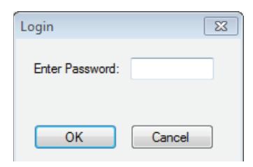
Figure 106 Login
2 Enter the reader password and press the OK button.
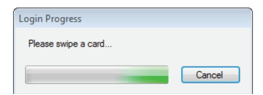
Figure 107 Swipe card
3 Swipe a card.
4 Once connection is established, the reader diagnostics will display.
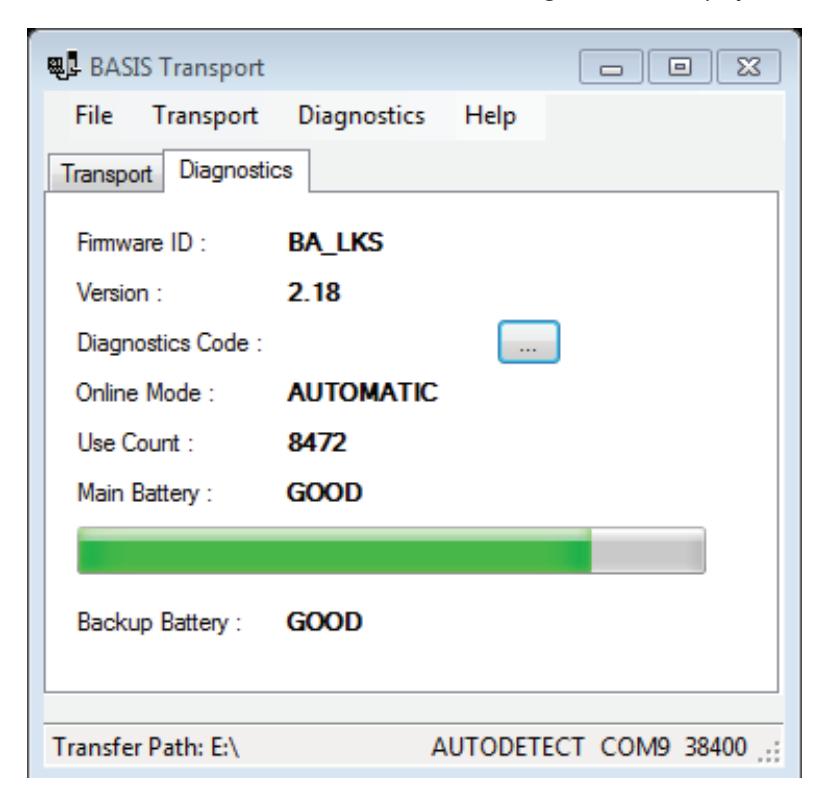
Figure 108 Diagnostics
The table below gives a definition for all of the fields in the Diagnostics window:
| This Field | Shows |
|---|---|
| Firmware ID | ID indicating the type of firmware in the lock. |
| Technical support personnel may ask you to | |
| provide this information. | |
| Version | Version number of the lock's firmware. Technical |
| support personnel may ask you to provide this | |
| information. | |
| Diagnostics Code | Hexadecimal number indicating firmware |
| conditions, such as firmware resets, that have | |
| occurred at the lock since the diagnostics code | |
| was last cleared. The code 0x00 means no | |
| conditions have occurred. | |
| To view the meaning of the code, click/tap the | |
| more button (). The Diagnostics Code window | |
| shows each active diagnostics code and its | |
| meaning. Click/tap the close button (X) to close | |
| the window. | |
| Online Mode | Whether the lock is under time zone control |
| (Automatic) or set to a specific mode, such as | |
| Locked or Unlocked. For more information, see | |
| "Set: Online Mode" on page 82. | |
| Use Count | Number of times access was granted since the |
| use count was last reset. To reset the use count, | |
| see "Reset: Use Count" on page 85. | |
| Main Battery | Current power level of the lock's battery pack. |
| No shading in the status bar indicates an Alarm | |
| condition. The batteries are dead and must be | |
| replaced. If the shading falls within the Warning | |
| range, the power level is 30% or lower. You | |
| should replace the batteries soon. If the shading | |
| falls within the Good range, the power level is | |
| between 30% and 100%. |
| Backup Battery | Current power level of the lock's coin cell | ||
|---|---|---|---|
| battery, used to back up the lock's memory if | |||
| the main battery pack dies or is disconnected. | |||
| If the backup battery is Bad, you should replace | |||
| it. Refer to the Electronic Stand-Alone Lock Service | |||
| Manual B.A.S.I.S. and Keypad EZ Locks (T80935). | |||
| Note: If using a B.A.S.I.S. G or V lock with a UVC | |||
| board, the backup battery is rechargeable and | |||
| not replaceable. | |||
Disconnect
1 To disconnect from the reader, go to the Diagnostics > Disconnect.
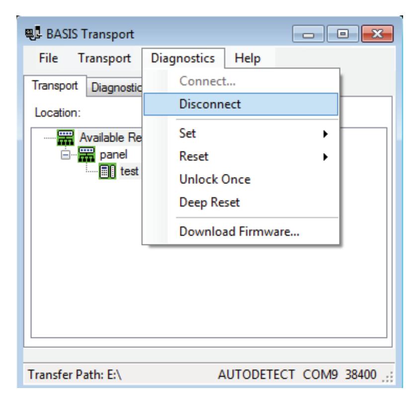
Figure 109 Diagnostic disconnect
Note The following diagnostic functions are performed while the Netbook/Notebook is already connected to the lock. You can exit diagnostics after performing any function by selecting Disconnect from the Diagnostic Menu.
Set
You have three options under the Set menu:
- Date/Time/DST enable
- Reader Technology
- Online Mode
Set: Date/Time/DST Enable
To set Day/Time to the current time, perform the following steps:
1 Select Diagnostics > Set > Date/Time/DST enable.
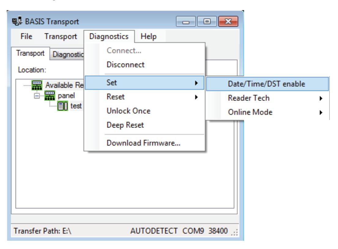
Figure 110 Date/Time
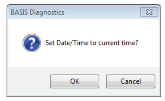
Figure 111 Set Date/Time
2 Click OK.
Set: Reader Technology
To set which reader technology the lock/reader is using, perform the following steps
1 Return to Diagnostics > Set > Reader Tech and select your choice of Proximity, Magnetic or Dual Val.
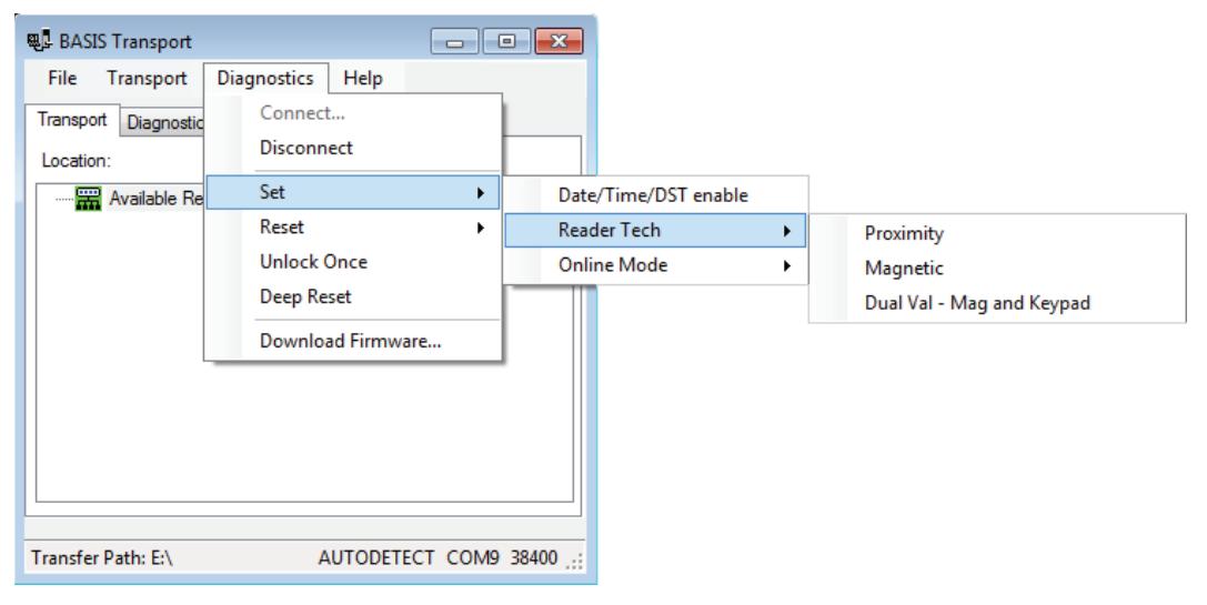
Figure 112 Set Reader Tech
Set: Online Mode
A B.A.S.I.S. offline lock mode of operation is determined by its programming. The diagnostics information for the lock indicates the locks current Online Mode setting.
For example, during an emergency you might set a lock's online mode to Unlocked so that emergency personnel can access the room. When the event is over, you must return the lock to its original online mode setting to resume normal operation.
The online mode will change only after disconnecting from the lock.
The following online modes are available:
- Automatic The lock is under time zone control.
- Card Any valid card in the lock's database can access the lock.
- Card and PIN Any valid card and PIN combination programmed in the lock's database can access the lock.
- Card or PIN Any valid card or PIN programmed in the lock's database can access the lock.
- Facility Code Any card with a valid facility code can access the lock.
- Locked The door is locked. All cards and PINs are denied access.
- Unlocked The door is unlocked.
To override the current online mode of the reader, perform the following steps:
1 Return to Diagnostics > Set > Online Mode and select your choice of Automatic, Card, Card and PIN, Card or PIN, Facility Code, Locked, or Unlocked.
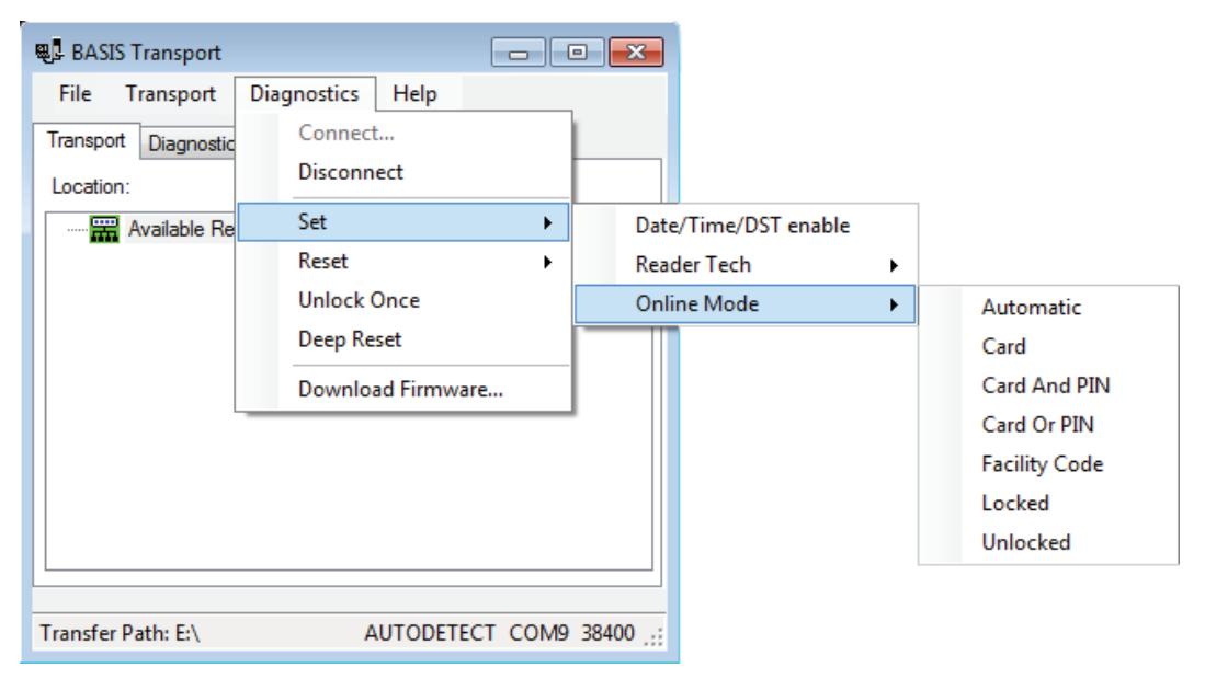
Figure 113 Online Mode options
Reset
You have two options under the Reset menu:
- Diagnostics Code
- Use Count
Reset: Diagnostics Code
Diagnostic codes are used to help identify issues with the lock, such as low battery alarms that might have occurred since the diagnostics code was last cleared. Perform the following steps:
1 Return to Diagnostics > Reset > Diagnostics Code.
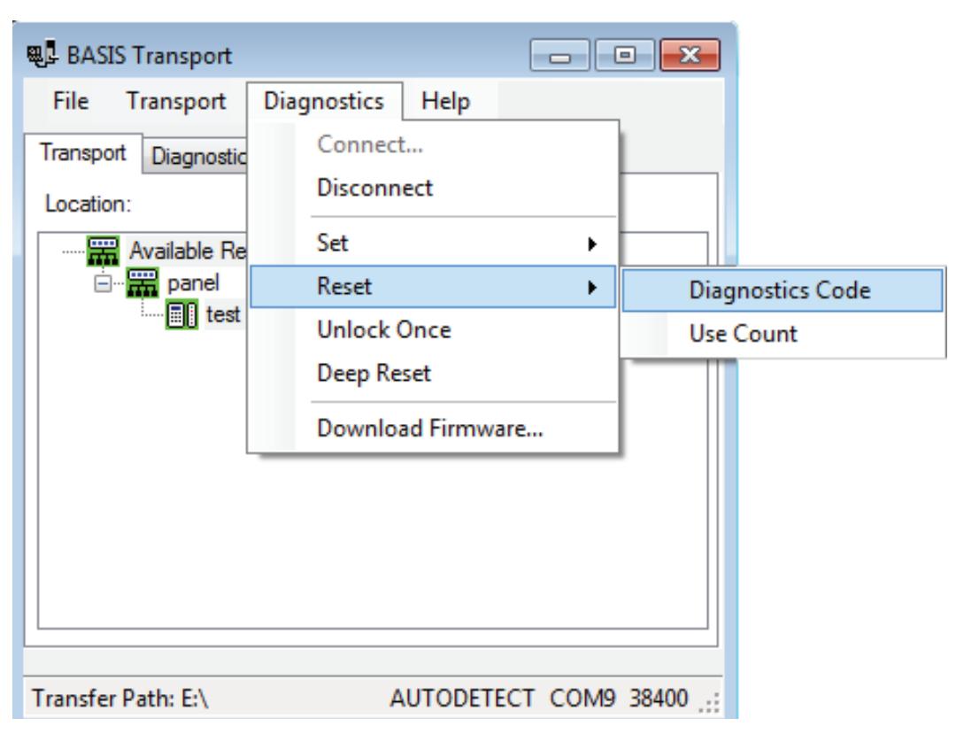
Figure 114 Reset Diagnostics Code
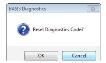
Figure 115 Reset Diagnostics Code
2 Click OK and the code will be reset to 0x0000.
Reset: Use Count
Every B.A.S.I.S. offline reader counts the number of times access has been granted to a card or pin since the use count was last reset. You can use this count to track how often a lock is accessed over time. Perform the following steps:
1 Return to Diagnostics > Reset > Use Count.
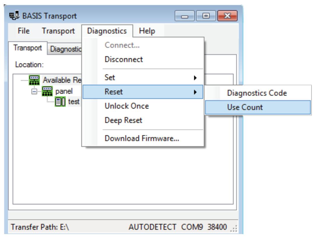
Figure 116 Reset Use Count
2 Click OK and the count will be reset to 0.
Unlock Once
You can use the Netbook/Notebook to unlock a door for the unlock duration programmed for a reader. This feature is useful when you need to access the inside of the door to replace the lock's batteries or perform other maintenance for the lock. Perform the following steps:
1 Go to Diagnostics > Unlock Once.
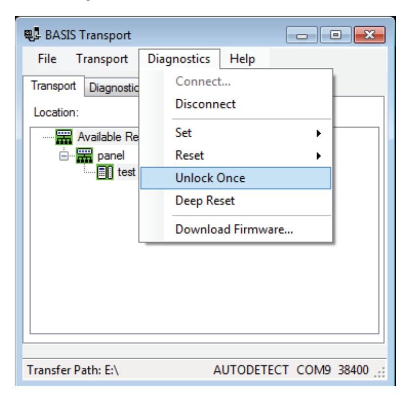
Figure 117 Unlock Once
2 Click OK if you wish to unlock momentarily.
Deep Reset
To reset the lock/reader to factory settings, perform the following steps:
1 Go to Diagnostics > Deep Reset.
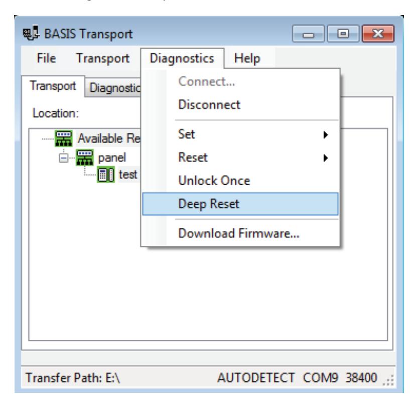
Figure 118 Deep Reset.
2 Click OK to Deep Reset
Download Firmware
To download any Firmware updates to your Netbook/Notebook, perform the following steps:
Note A firmware download is only available if the lock is fitted with the UVC board.
1 Go to Diagnostics > Download Firmware.
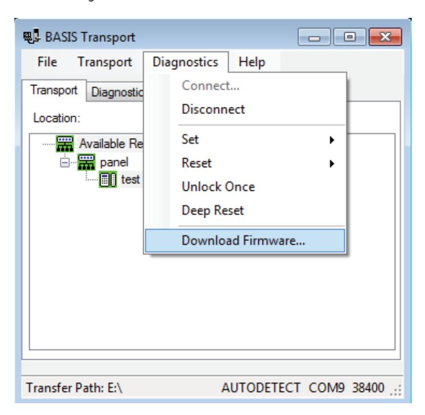
Figure 119 Download Firmware
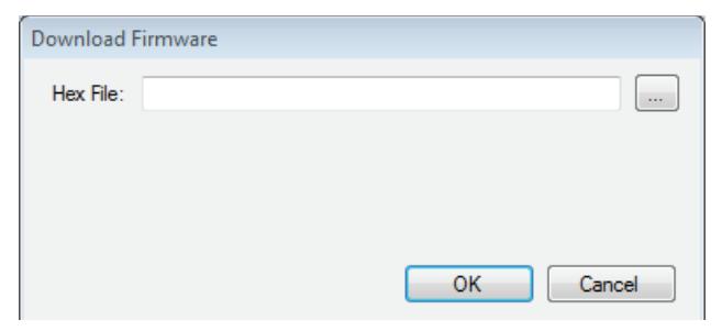
Figure 120 Hex file
2 Click on to browse for your firmware hex file.
Note Firmware files are available by contacting Technical Support at (800) 392-5209.
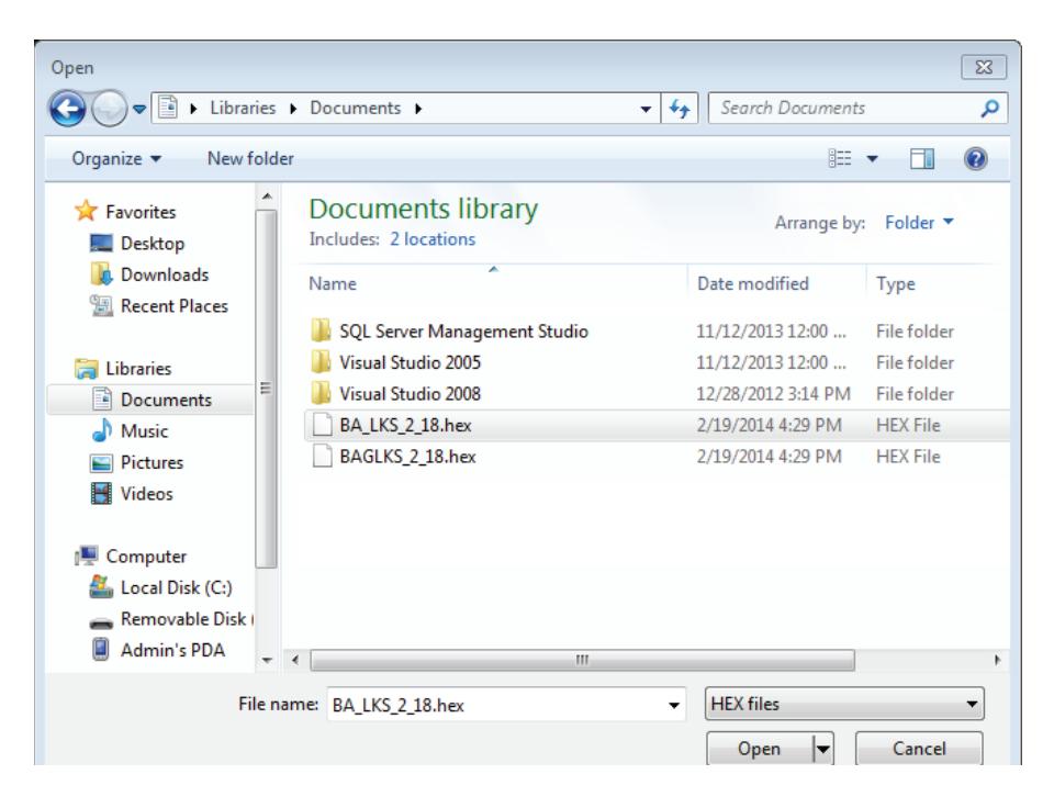
Figure 121 Open hex file
3 Select your Hex file and Click Open.
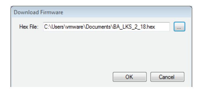
Figure 122 Hex file
- Click OK and the download will begin.
- Once the download has completed, you should hear the reader make three beep sounds. This confirms that the reader has restarted to complete the Firmware download.
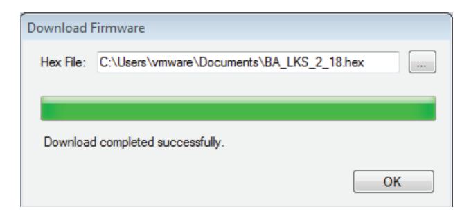
Figure 123 Download completed successfully
Click OK to exit.
To Manually Change the PIN in a Dual Validation Lock
You can change your PIN only during a time period when both your card and PIN are required to unlock the door.
Warning: Do not write your PIN on your card or in a place where someone might see it.
- 1 Use your card at the lock.
-
2
From the lock keypad, immediately enter:
- * + your current PIN + #
The red light remains on, indicating that you can change your PIN.
3 Immediately enter:
your new PIN + #
4 Immediately re-enter:
your new PIN + #
The green light flashes to indicate that you successfully changed your PIN.
Note If you make a mistake re-entering your new PIN, three short tones sound and the red light turns off. Start over with step 1 and use your old PIN for step 2.
Example of changing your PIN
- 1 Use your card.
- 2 Enter * 1 2 3 4 #
- 3 Enter * 4 3 2 1 #
- 4 Re-enter * 4 3 2 1 #
Note If pin changes happen at the door for UVC users and a cardholder download is pushed, the pins are overwrittten by pins pushed during the download.
Set Up and Maintain 116
4
Managing B.A.S.I.S.Cardholders
Managing cardholders involves three activities:
- Creating cardholders
- Searching for cardholders
- Encoding cardholders' badges
These activities form the bulk of day-to-day operations that are necessary to administer B.A.S.I.S. Offline locks. This section describes these activities.
Creating Cardholders
The first of the three activities, creating cardholders involves the following:
- Adding
- Modifying
To Create a Cardholder:
- 1 From System Administration, click Administration > Cardholders.
- 2 Click Add.
The Add Cardholders window displays
At a minimum, complete Last name, First name, and select a Badge type.
Figure 124 Adding cardholders
- 3 Complete all appropriate fields in the form.
- 4 Click the Badge tab.
The badge form displays:
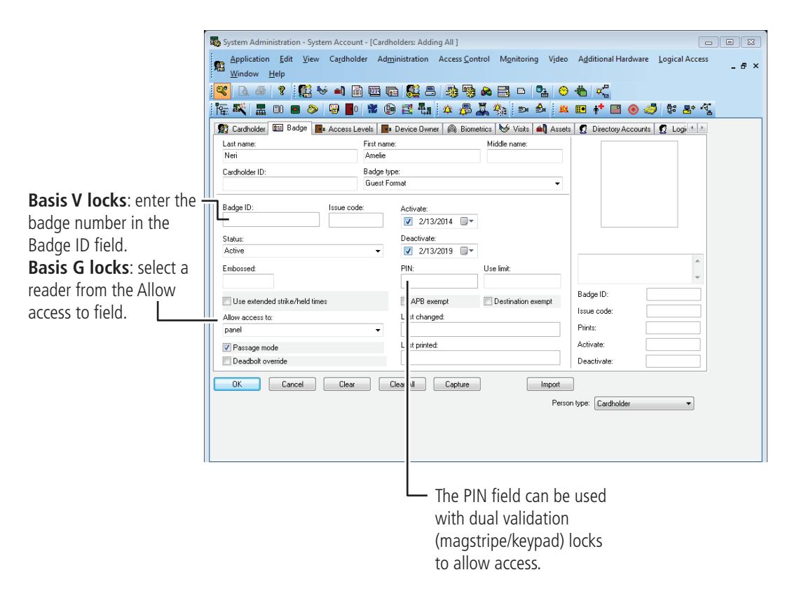
Figure 125 Badge Form
- 5 Complete all appropriate fields in the form. For a compete list of field definitions, see the System Administration Help or the Glossary.
- 6 Click OK.
- 7 To encode the cardholders badge, see "Encoding Existing Cardholders" on page 123.
Modifying Cardholders
When a cardholder's name, location, title, or any other piece of data changes, use the modify function of the same cardholder forms that you used in adding a cardholder.
To Modify a Cardholder
- 1 From System Administration, click Administration > Cardholders.
- 2 Search for the cardholder record that you want to modify. For more information on searching, see page 121 .
- 3 Click Modify.
The Modify Cardholders window displays
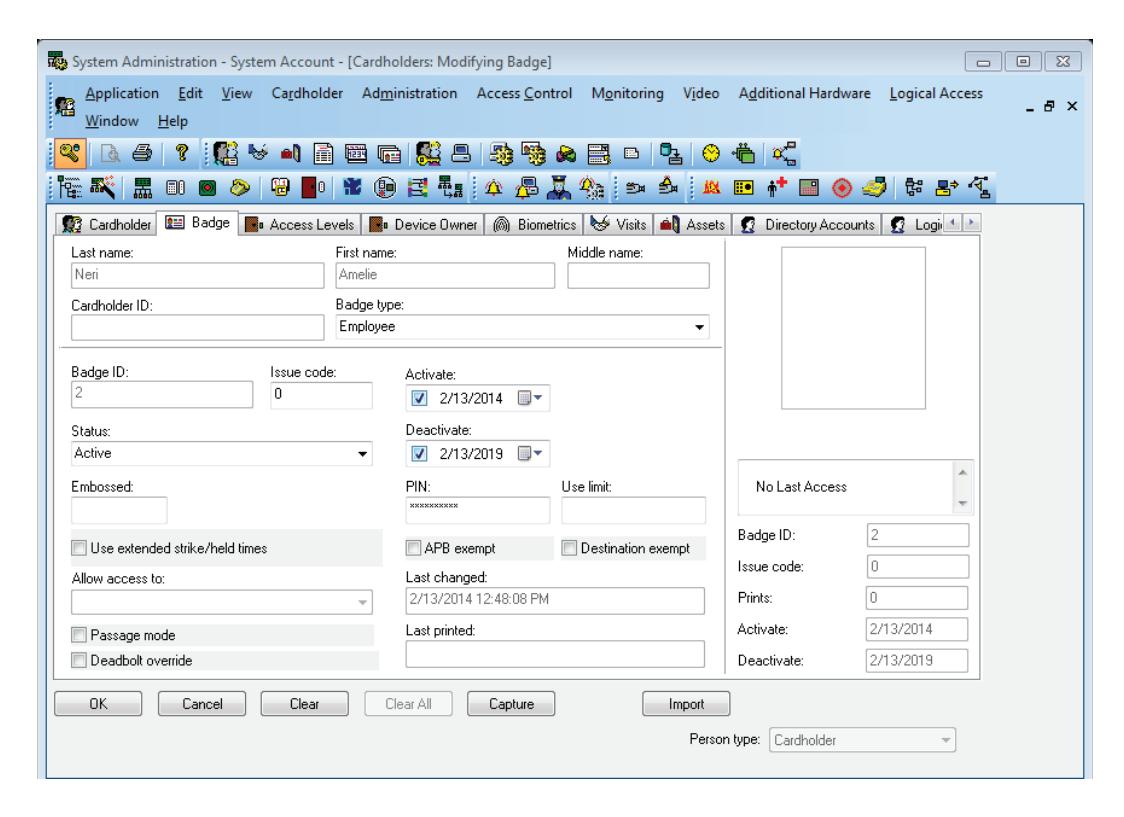
Figure 126 Modifying cardholders
- 4 Select and change the field or fields that you want to change.
- 5 Click OK.
Note: Modify mode will only allow you to make changes to the specific tab that you selected Modify in. Complete all necessary changes before selecting other tabs to be modified.
Searching for Cardholders
The search module of B.A.S.I.S. is extensive and is an important function that can be used for many reasons. It's important to understand how to search if you're:
- modifying a cardholder
- checking the status of a cardholder
- inquiring about a cardholder's address, phone number, etc.
Search offers an efficient way to find a cardholder or a group of cardholder records using any known piece of the cardholder's data.
To search for a cardholder or a group of cardholders
- 1 From System Administration, click Administration > Cardholders.
- 2 Click Search.
The Cardholder fields are cleared
The cardholder data fields are all cleared to enable you to search for any cardholder record, even if you know as little as one piece of cardholder data. Cardholders can be searched for using one, two or more fields. This enables you to narrow down the list of cardholder records. Once a cardholder or a groups of cardholder records are displayed, you can page through the records one by one.
- 3 Select the tab that you want to search from. You can search from any one of the following tabs. Each tab has its own unique search features:
- cardholder
- badge
- access levels
4 "Select and complete at least one field to search on." For example, to search for all students in the Johnson East dormitory, the following screen shows the required data selection:
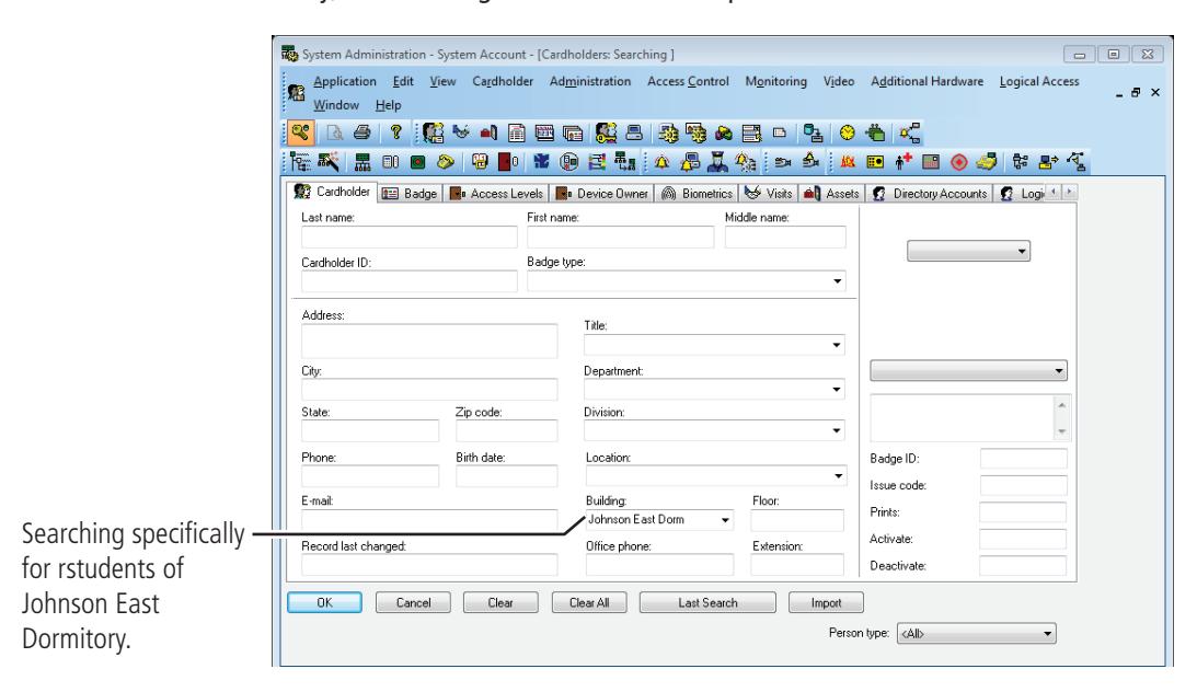
Figure 127 Example of searching for all Johnson East, dormitory students
5 Click OK.
The search arrows appear in the lower right-hand corner of the screen.
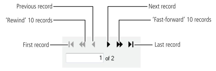
Figure 128 Search arrow definitions
6 Use the search arrows to page through the records that met the search criteria.
Encoding Existing Cardholders
Once a cardholder has been added with the proper badge information, you're ready to encode the card.
To encode an existing cardholder's badge
- 1 From System Administration, click Administration > Cardholders.
- 2 Click the Badge tab.
- 3 Search for the cardholder record that you want to encode. For more information on searching, see page 121 .
The Encode badge form displays:
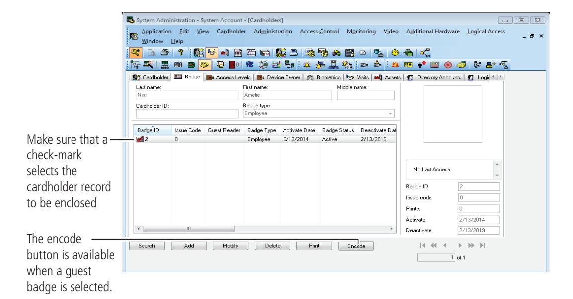
Figure 129 Getting ready to encode a guest badge
- 4 Make sure that the check mark selects the record that you want to encode.
- 5 Click Encode.
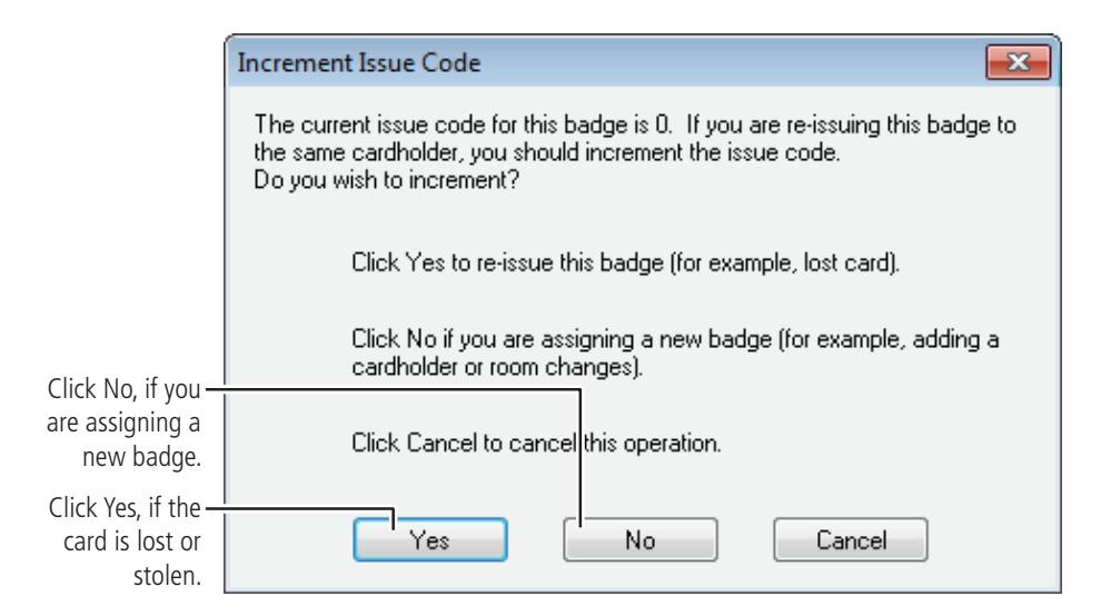
Figure 130 Question regarding the issue code
6 Click No.
The Encode Badge window displays:
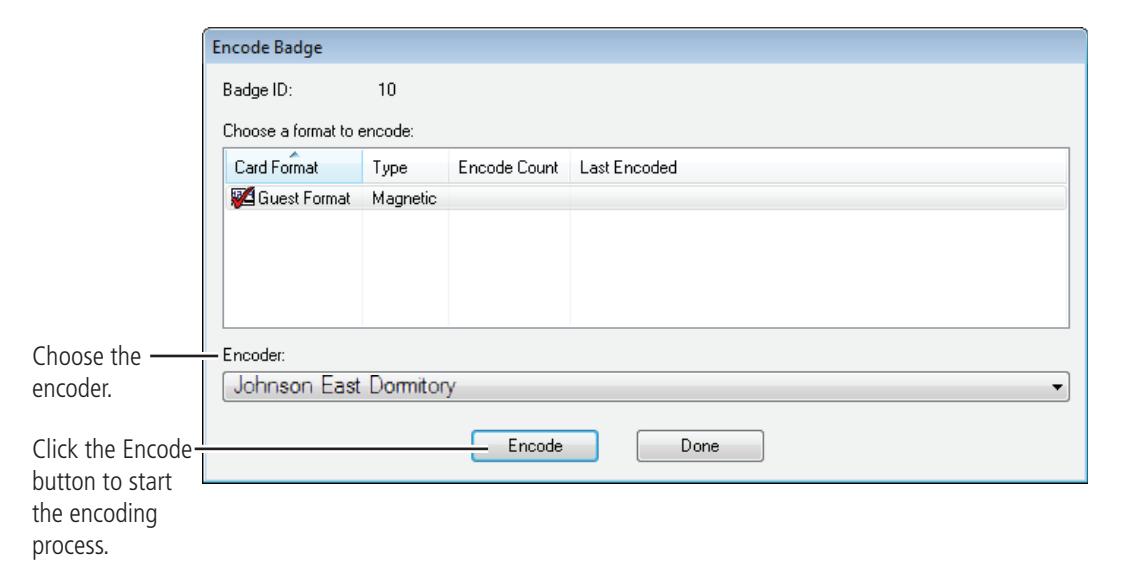
Figure 131 Choosing a card format to encode
7 Make sure that the check mark is on the card to be encoded, then click Encode.
The encoder is initialized and prompts you to swipe the card:
8 Slowly swipe the card through the encoder as shown below.

Figure 132 Swiping the magstripe card through the encoder
Glossary
access level An access control relationship made between a reader or
readers and a time zone or time zones. An access level is assigned to a badge ID for the purpose of granting access
through a reader or readers during a specified time.
access panel A circuit board with on-board memory that is responsible for making most of the decisions in an access control system.
activation/deactivation date The date that a credential becomes active or expires.
ActiveSync/Mobile Device Center A Microsoft utility designed to synchronize the data between
a PC-based application and a PDA application. Used to synchronize the data between B.A.S.I.S. and B.A.S.I.S.
Transport.
antipassback A configuration limiting the ability of consecutive uses for a credential at a reader. Usually, configured with readers
installed on both the secure and non-secure side of an opening. Once a credential has been used in a reader to gain access on one side of the opening, the credential cannot be used in the same reader until the credential is used to gain access to a reader from the opposite side of the opening.
APB exempt Antipassback exempt. The cardholder with this privilege is
exempt from antipassback rules.
badge The credential or token that carries a cardholder's data.
badge ID Part of the access control information that is encoded to a
token. This information, usually numerical, is unique to a
particular credential holder.
badge type Used in B.A.S.I.S. to determine a number of parameters for a particular badge ID. These parameters include the activation and deactivation dates, default access groups, the applied badge design, the printer used to print the badge, the required data fields for cardholder entry, and a range of badge ID's to be used for a specific group of badges.
B.A.S.I.S. Transport The application that runs on a PDA or Netbook/Notebook designed to update B.A.S.I.S. locks and retrieve lock history.
battery alarm The diagnostic code that a B.A.S.I.S. Lock displays when the main batteries are low.
battery warning The diagnostic code that B.A.S.I.S. Transport displays when the main batteries must be replaced.
card format The way that data is arranged and ordered on the card.
cardholder An individual who is issued a particular credential.
chassis type The designation that defines the physical lock type. Three types exist: cylindrical, mortise, or exit hardware. See those terms for more information.
communication server The server application designed to provide network services to access panels, readers, PCs and PDAs.
credential A physical token, usually a card or fob, encoded with access control information.
cylindrical Lock chassis that installs into a circular bore in the door.
deadbolt override The ability for an authorized credential to retract both the spring latch and the deadbolt when the dead bolt is engaged.
diagnostic code The code in B.A.S.I.S. Transport that identifies the processing
error.
encoder The device, connected to a PC running B.A.S.I.S., used to encode magnetic stripe cards or smart cards.
ethernet The most common networking standard in the world, formally
known as IEEE 802.3.
exit hardware Lock chassis type that supports exit hardware trim lock.
extended unlock The extra period of time the lock will unlock when an authorized credential with extended unlock privileges is
presented.
facility code Part of the access control information that can be encoded to a credential. This information, usually numerical, is unique to a group of credentials. Usually this feature is used to authenticate a credential to a particular organization.
guest A feature that enables you to add and delete cardholders to and from a lock without having to go out to a lock to
reprogram it.
Glossary 128
IP address The numeric address (like 192.168.1.1) that identifies each
device in a TCP/IP network. input A hardware connection point used for status reporting of a particular sensor.
input A hardware connection point used for status reporting of a
particular sensor.
intelligent system controller (ISC) See access panel.
issue code Part of the access control information contained on a
credential that allows reuse of the badge ID when a credential is lost, damaged, or stolen. Usually one or two digits in length, this code increments forward when creating a new credential. Access is granted only when the badge ID and the
issue code match the current database information.
look ahead An offline feature where a higher issue code for a particular
badge ID knocks out the same badge ID with a lower issue code from an offline lock when the badge ID with higher issue
code is presented to the lock.
mortise A lock chassis that installs into a mortised cavity in the edge
of a door.
netbook/notebook A small laptop computer that is designed primarily for
accessing Internet-based applications.
output A B.A.S.I.S. on-board relay or switch that is configurable to
follow the status of an input, system condition, or a time
zone.
passage mode The ability to double present an authorized credential within
the strike time to unlock an opening. The lock is returned to its original status by a second, double presentation of an
authorized credential..
PDA Personal Digital Assistant.
programming cable The cable used to connect the mobile device to the B.A.S.I.S.
Lock.
reader interface module (RIM) A circuit board that acts as the integration point for access
activity at a particular opening. The RIM integrates Card Reader, Door Position, Request-to-Exit, and Lock Control
activity with the ISC.
request to exit A sensor usually installed on the non-secure side of the door
that will mask the door position switch upon activation.
time interval A specific range of time, which corresponds to a particular day
or days of the week. A time zone can be comprised of several,
individual intervals.
timezone A defined range of time for assignment to various access
control activities. A time zone may be applied to a reader or readers when creating an access level, to a reader to change the mode of operation, to a relay to activate and deactivate, to an input to mask and unmask, and a host of other
operations.
two-card control The requirement for the presentation of two
separate,authorized credentials in order to gain entry through
an access controlled opening.
unlock duration The time that the lock momentarily unlocks.
use limit A configuration limiting a credential to a defined number of
uses.
Glossary 130