BEST Mechanical Locks 9K Series Catalog
Open the original PDF document
View PDF

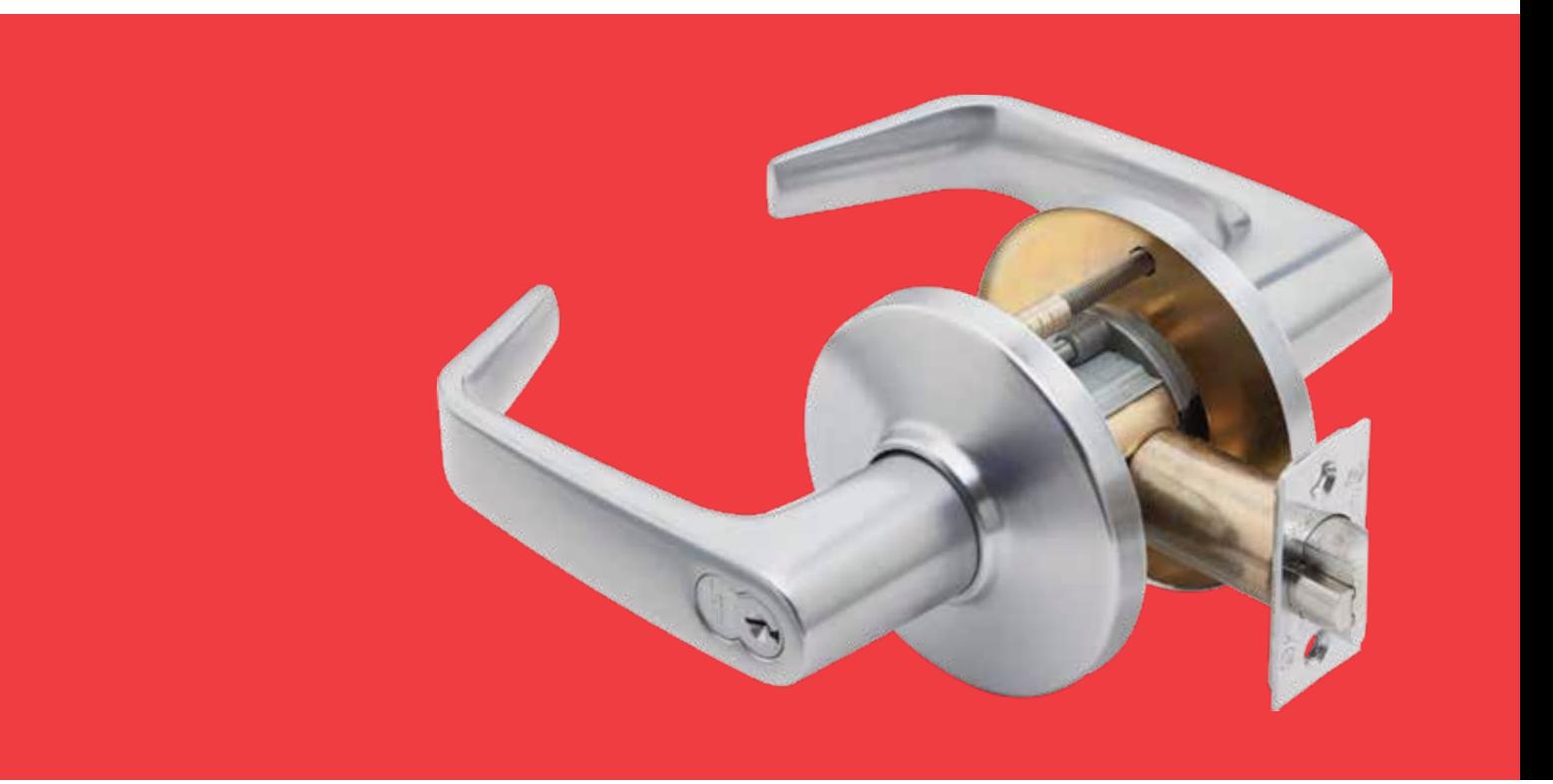
9K Series
Heavy Duty Cylindrical Locks – Levers

TABLE OF CONTENTS
| Features2 | Deadlocking Latches & Strikes10 |
|---|---|
| Specifications2-3 | Lever Features & Dimensions5 |
| How to Order3 | Function6-9 |
| Shipping Weights4 | Strike & Door Preparation11 |
| Lever Styles & Trim4 | 9K Sample Specifications11 |
| CORMAX™ Patented Keying System10 | Service Equipment12 |
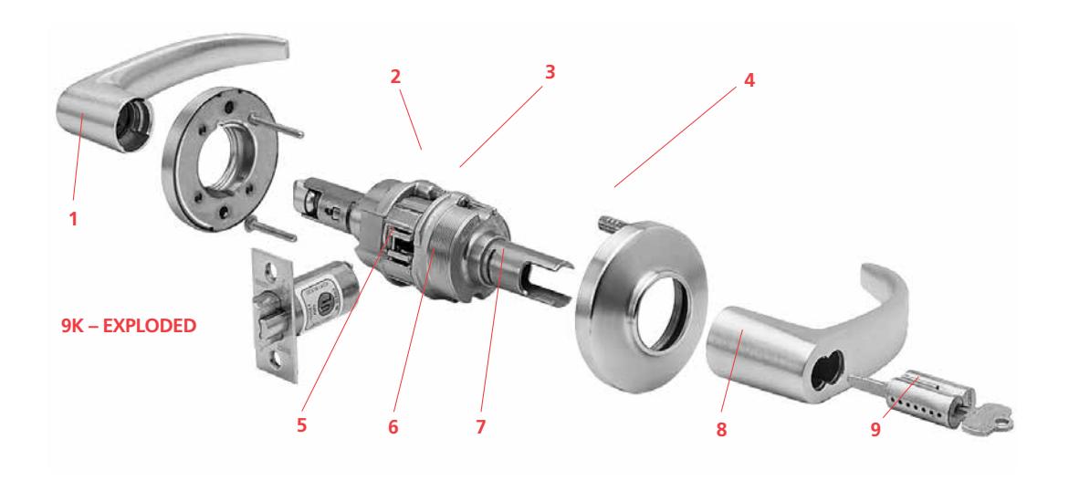
Features
- 1. For versatile applications, lever by knob trim variations are available.
- 2. Rose locking pin and rose assembly design offers great torque resistance. It prevents the locking pin from twisting, bending, or breaking under attack.
- 3. The innovative design of the slotted key release cam and locking lug assembly create maximum attack resistance. Even though damaged, the lock still allows key access. In addition, the lever is fully functional from the inside. The hub-mounted torsion spring and strong retractor springs help prevent lever sag and offer a smooth and snappy operation.
- 4. Strong through-bolt mounting studs increase torque resistance. Heavy rose liner material is highly attack resistant.
- 5. Strong retractor springs provide resistance to lever sag.
- 6. Zinc hubs with a shrouded locking lug, guaranteeing higher quality and increased torque resistance.
- 7. The outside lever sleeve is a seamless one piece construction made of a hardened steel alloy that provides additional reinforcement in the locking lug slot.
- 8. Lost Motion feature available allowing 45º lever rotation in either direction without engaging retractor assembly.
- 9. Interchangeable core allows for quick re-keying and customized masterkeying.
Specifications
ADA–Americans With Disabilities Act: 9K series – The design and operation of the BEST® cylindrical lock meets the intent of the standard for ANSI A117.1 section 404.2.6
Builders Hardware Manufacturers Association: 9K series – Listed by BHMA for A156.2, Series 4000, Grade 1.
Underwriters Laboratories®: 9K series – Listed by Underwriters Laboratories for use on 3 Hr, A label for single or double swinging doors.
Florida Building Code and Miami-Dade County Code: 9K series – 9/16" latch throw – Listed by Florida Building Code and Miami-Dade County at ± 75 PSF for single doors. 9K series – 3/4" latch throw – Listed by Florida Building Code and Miami Dade County at ± 80 PSF for single doors and ± 50 PSF for double doors.
"WS" option must be ordered for the lock to include a "Miami-Dade County Product Control Approved" label for inspection purposes.
California State Fire Marshal: 9K series – Listed with California State Fire Marshal.
9K series 14 & 15 lever conforms with California Title 24.


Backset – 2 3/4" standard, 3 3/4" and 5" available.
Chassis – Critical latch and chassis components are brass or corrosion-treated steel. 2 1/16" diameter to fit 2 1/8" hole in door (Conforms to ANSI A115.2). Lost Motion feature available as an option. (see page 5 for options/features).
Door thickness – Available for 1 3/4" to 2 1/4" doors only. Spacers available for 1 3/8" doors.
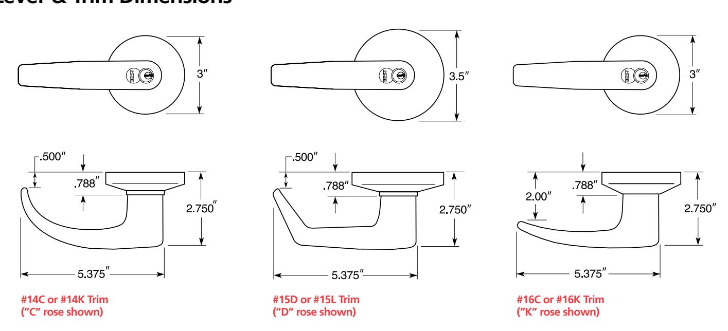
Roses – C – 3" Convex, D – 3 1/2" Convex, K – 3" Convex-no ring, L – 3 1/2" Convex-no ring
Products protected by one or more of the following patents – 5,590,555 5,794,472 Other products patent pending.
Finishes –
| (BHMA) US | DESCRIPTION | (BHMA) US | DESCRIPTION | (BHMA) US | DESCRIPTION | |||
|---|---|---|---|---|---|---|---|---|
| 605 | 3 | bright brass | 613 | 10B | oxidized satin bronze, | 622 | 19 | flat black |
| 606 | 4 | satin brass | oil rubbed | 625 | 26 | bright chromium plated | ||
| 611 | 9 | bright bronze | 618 | 14 | bright nickel plated | 626 | 26D | satin chromium plated |
| 612 | 10 | satin bronze | 619 | 15 | satin nickel plated | 690 | 20 | dark bronze |
Antimicrobial Finish – 626AM satin chrome plated with UltraShield™ antimicrobial protected coating
The BEST UltraShield™ finish inhibits the growth of bacteria and other microbes on the surface of the hardware.

NOTE: BEST's UltraShield™ option is recommended for use on any hardware application where product cleanliness is a high priority. i.e;. Hospital/Healthcare, Elderly Care, Education, Transportation, Food-Service, Hospitality.
Latch – Solid brass 9/16" throw. Front 2 1/4" x 1 1/8" beveled.
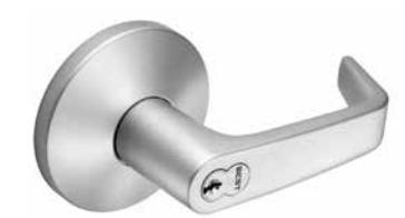
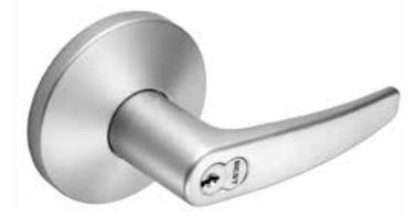
Lever handles – Lever handles are a high-quality zinc alloy. Trim components are brass or bronze. Body is approximately 5/8" in diameter; Handle is approximately 4 3/4" long (from center-line of chassis). #14 and #15 levers conform to California Administrative Code Title 19 and Title 24. All three styles of levers conform to the Illinois Accessibility Standard.
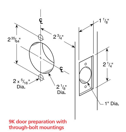
Mounting – In addition to standard door preparation (ANSI A115.2 for 1 3/4" doors), two additional holes are needed for through-bolts. Through-bolts require two 5/16" diameter holes located at 12 o'clock and 6 o'clock positions. A drill jig can be ordered to insure accuracy of the holes. (see KD303 page 5).
Projection on door – Approx. 2 3/4" when mounted on 1 3/4" door.
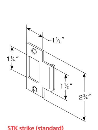
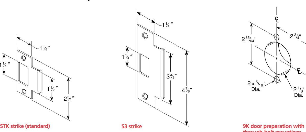
Strike – STK: Conforms to ANSI A115.2 (2 3/4" x 1 1/8" with curved lip & box). S3: Conforms to ANSI A115.2 for 1 3/4" doors (4 7/8" x 1 1/4" with curved lip). S3-7/8:
Conforms to ANSI A115.2 for 1 /4" doors (4 7/8" x 1 7/8" flat)
How to Order
| 9K | 3 | 7 | AB | 15 | A | STK | 626 | |
|---|---|---|---|---|---|---|---|---|
| Series | Backset |
Core
Housing |
Function
Code |
Lever |
Rose
Style |
Strike
Package |
Standard
Finishes |
Options |
| 9K |
3 – 2 3/4"
4 – 3 3/4" 5 – 5" |
0– keyless
7– 7-pin housing accepts all BEST® cores |
AB– entrance
D– storeroom L– privacy N– passage R– classroom etc. |
14–
curved return 15– contour angle return 16– curved no return |
C– 3"
convex D– 3 1/2" convex K– 3" convex - no ring L– 3 1/2" convex - no ring |
STK– 2 3/4"
ANSI S3– 4 7/8" ANSI S3– 7/8- 7/8" flat strike |
605 606
611 612 613 618 619 622 625 626 690 |
AL– abrasive lever
LL– lead lined LM– lost motion RQE– request to exit** SH– security head screws TL– tactile lever 3/4– 3/4" throw latch 7/8" LTC– flat lip strike NOTE: specify inside (I), outside (O), or both (B) for AL,TL options |
| pages 6-9 | pages 4-5 | pages 4-5 | page 11 | page 5 |
* Handles are made from a zinc alloy, and have been plated to be equivalent in appearance to the finishes listed. For information on 9K non-IC products please refer to BEST's non-IC keying products brochure.
** RQE option requires modification to chassis and is sold with assembly unit only.
Shipping Weights
The chart is the approximate shipping weight for the standard 9K functions locksets. This weight includes the weight of the lockset with the "#15" style lever, "K" style rose, latch, strike package, and box. Listed separately are the approximate weights for "with core" and "less core" shipments.
|
Lock Function
Nomenclature |
Case Quantity |
Shipping Weight
With Core |
Shipping Weight
Less Core |
|---|---|---|---|
| Y | 9 | 31 lbs | |
| N | 9 | 40 lbs. | |
| L,NX,P | 9 | 40 lbs. | |
| AB,D,E,H,HJ,R,T | 9 | 42 lbs. | 40 lbs. |
| C,G,IN,S,W | 9 | 44 lbs. | 40 lbs. |
Lever Styles and Trim

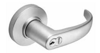
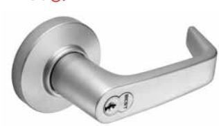
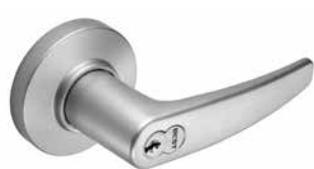
#14D
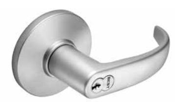
#15D
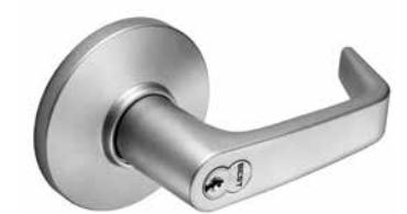
#16D
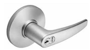
#14K
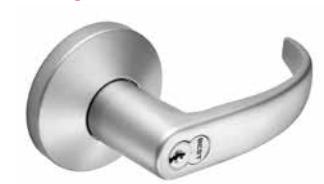
#15K
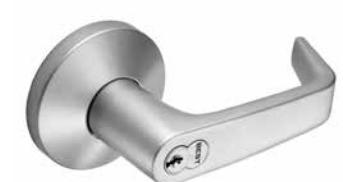
#16K
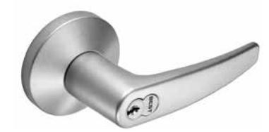
#14L
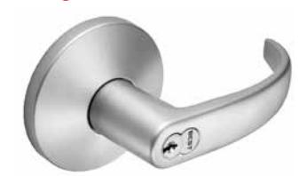
#15L
#16L

Lever Features
Abrasive Lever Option
Besides complying with a wide variety of accessibility codes and ordinances, BEST lever handles are available with a special abrasive feature. Abrasive strip on the lever immediately identifies warnings on doors to hazardous areas for the blind. To order: Designate "AL" on How to Order (page 3). Note: abrasive strip is available on all levers, except #14, #15, #16 levers in 613 finish.
Lost Motion Feature
The Lost Motion feature allows the lever handle to move 45 degrees from parallel to the horizontal plane without engaging the latchbolt assembly. When the lockset is in the locked mode, this feature makes over-torque or over-lever-age abuse more difficult to achieve. To order: designate "LM" on How to Order (page 3).
Non IC Lever Option
The 9K heavy duty cylindrical lock may be adapted to existing keying systems by using a special retrofit lever and throw member that will accept 6 pin single shear-line cylinders from non BEST manufacturers. No internal modifications are required to adapt the 9K to cylinders from the following manufacturers: Corbin-Russwin, Medeco, Sargent, Schlage, Yale. Refer to BEST® non-IC keying products brochure for more details.
RQE Feature
The 9K lever handle cylindrical can be built to incorporate a request-to-exit (RQE) switch. A normally open switch provides momentary switch closure when the inside lever is rotated. RQE option requires modification to chassis and is sold with assembly unit only. To order: designate "RQE" on How to Order (page 3).
Tactile Lever Option
Tactile levers may be used in areas where improved grip is required or as a warning in hazardous areas. Grooves are machined into the back of the hand grasp portion of the lever to improve grip and/or to provide a sensory warning in hazardous areas. This option can be used for Blind, Safety or Accessibility applications. To order: Designate "TL" on How to Order (page 3).
Lever & Trim Dimensions
| Description | Outside Lever | Inside Lever | |||
|---|---|---|---|---|---|
| Function & Diag. | Latch operated by |
Locked by
Unlocked by |
Locked | Unlocked | |
| (ANSI No.) | by | by | |||
| Single keyed | |||||
| Entrance (AB) F109 |
• Rotating the inside lever,
• Rotating the outside lever– only when the inside push button is out, • Turning the key in the outside lever |
• Pushing the inside button,
• Pushing and turning the inside button. Turning the button keeps the outside lever locked until the button is turned back |
• Turning the key in the outside
lever, (only when the button is not turned) • Rotating the inside lever, (only when the button is not turned). • Closing the door (only when the button is not turned) |
Cannot be
locked |
Always
unlocked |
| Storeroom (D) F86 |
• Turning the key in the
outside lever, • Rotating the inside lever |
Always fixed | Cannot be unlocked |
Cannot be
locked |
Always
unlocked |
| Service Station (E) F92 |
• Rotating the inside lever,
• Rotating the outside lever only when the inside push button is out. • Turning the key in the outside lever |
• Pushing the inside button,
• Pushing and turning the inside button. Turning the button keeps the outside lever locked until the button is turned back |
• Turning the key in the outside
lever, • Rotating the inside lever, • Closing the door-only when the button is not turned, • Turning back the slotted button |
Cannot be
locked |
Always
unlocked |
|
Hotel Guest Room (H) F93
(Indicator Included) |
• Rotating the inside lever,
• Turning the key in the outside lever-only when the inside push button is out, • Removing the core with a control key and using a special emergency key |
Always fixed |
Key block feature is released by:
• Rotating the inside lever, • Closing the door |
Cannot be
locked |
Always
unlocked |
| Pushing the inside button projects an "occupied" indicator in the outside lever and blocks all operating keys. | |||||
|
Hotel Guest Room (HJ)
(No Indicator) |
• Rotating the inside lever,
• Turning the key in the outside lever-only when the inside push button is out, • Removing the core with a control key and using a special emergency key |
Always fixed |
Key block feature is released by:
• Rotating the inside lever, • Closing the door |
Cannot be
locked |
Always
unlocked |
| Pushing the inside button blocks all operating keys, but no "occupied" indicator is projected. | |||||
| Classroom (R) F84 |
• Rotating the inside lever,
• Turning the key in the outside lever, • Rotating the outside lever when not locked by key |
Turning the key in the outside
lever, |
Turning the key in the outside
lever, |
Cannot be
locked |
Always
unlocked |
| Dormitory (T) F90 |
• Rotating the inside lever,
• Rotating the outside lever when not locked by key or push button |
• Turning the key in the outside
lever, • Pushing the button on the inside lever |
• Turning the key in the outside
lever, • Rotating the inside lever (only when locked by push button), • Closing the door (only when locked by push button) |
Cannot be
locked |
Always
unlocked |
| Entrance/Office (UA) |
• Rotating the inside lever,
• Rotating the outside lever– only when the inside push button is out, • Turning the key in the outside lever |
• Pushing the inside button,
• Pushing and turning the inside button. Turning the button keeps the outside lever locked until the button is turned back |
• Turning the key in the outside
lever, (only when the button is not turned) • Rotating the inside lever, (only when the button is not turned). |
Cannot be
locked |
Always
unlocked |
| Double keyed | |||||
| Corridor (C) F88 |
• Rotating the inside lever,
• Rotating the outside lever when not locked by key, • Turning the key in the outside lever |
Turning the key in the inside lever |
Turning the key in the inside
lever |
Cannot be
locked |
Always
unlocked |
* ATTENTION: Locksets that secure both sides of the door are controlled by building codes and the Life Safety Code. In an emergency exit situation, failure to quickly unlock the inside lever could be hazardous or even fatal.

| Description | Outside Lever | Inside Lever | |||
|---|---|---|---|---|---|
|
Function & Diag.
(ANSI No.) |
Latch operated by | Locked by | Unlocked by |
Locked
by |
Unlocked
by |
| Double keyed (Continued) | |||||
| Storeroom* (G) F91 |
• Rotating the outside lever
when not locked by key, • Rotating the inside lever when not locked by key |
• Turning the key in the inside
lever, • Turning the key in the outside lever |
• Turning the key in the inside
lever, • Turning the key in the outside lever |
• Turning the
key in the inside lever, • Turning the key in the outside lever |
• Turning the
key in the inside lever, • Turning the key in the outside lever |
| Turning the key in either the inside or the outside, locks or unlocks both sides. | |||||
| Intruder (IN) F11 |
• Rotating inside lever,
• Rotating outside lever only when not locked by inside or outside key |
• Turning key in the inside lever,
• Turning the key in the outside lever |
• Turning key in the inside lever,
• Turning the key in the outside lever |
Cannot be
locked |
Always unlocked |
| Communicating* (S) F80 |
• Turning the key in the inside
lever, • Turning the key in the outside lever, • Rotating the inside or outside lever (if unlocked) |
Turning the key in the outside
lever |
Turning the key in the outside
lever |
Turning the key
in the inside lever |
Turning the key
in the inside lever |
| Turning the key in either lever, locks or unlocks its own lever independently | |||||
| Communicating* (W) F87 |
• Turning the key in the
inside lever, • Turning the key in the outside lever |
Always fixed | Cannot be unlocked | Always fixed |
Cannot be
unlocked |
| Keyless | |||||
| Privacy (L) F76 |
• Rotating the inside lever
• Rotating the outside lever only when the inside push button is out |
Pushing the inside button |
• Rotating the outside slotted
button, • Rotating the inside lever, • Closing the door. |
Cannot be
locked |
Always unlocked |
| Passage (N) F75 |
• Rotating the inside lever,
• Rotating the outside lever |
Cannot be locked | Always unlocked |
Cannot be
locked |
Always unlocked |
| Exit (NX) F89 | Rotating the inside lever | Always fixed | Always fixed |
Cannot be
locked |
Always unlocked |
| Patio (P) F77 |
• Rotating the inside lever,
• Rotating the outside lever only when the inside push button is out |
Pushing the inside button |
• Rotating the inside lever,
• Closing the door |
Cannot be
locked |
Always unlocked |
| Exit (Y) | Rotating the inside lever |
Cannot be
locked |
Always unlocked | ||
| Single Dummy Trim (1DT) | This is a single, surface-mounted lever for an inactive door or a non-latching door |
* ATTENTION: Locksets that secure both sides of the door are controlled by building codes and the Life Safety Code. In an emergency exit situation, failure to quickly unlock the inside lever could be hazardous or even fatal.
| Description | Outside Lever | Inside Lever | |||
|---|---|---|---|---|---|
|
Function &
Diag. (ANSI No.) |
Latch operated by | Locked by | Unlocked by |
Locked
by |
Unlocked
by |
| Keyless (Continued) | |||||
|
Double Dummy Trim
(2DT) |
This is a through bolt mounted pair of matching levers for an inactive door or a non-latching door | ||||
| Electromechanical | |||||
|
Electrically
Locked (DEL) |
• Rotating the inside lever,
• Rotating the outside lever only when power is off, • Turning the key in the outside lever |
• Applying 24 Volts DC.
• Outside lever remains locked only while power is on |
Switching off 24 Volts DC |
Cannot be
locked |
Always unlocked |
|
Electrically
Unocked (DEU) |
• Rotating the inside lever,
• Rotating the outside lever only when power is on, • Turning the key in the outside lever |
Switching off 24 Volts DC |
• Applying 24 Volts DC
• Outside lever remains unlocked only while power is on |
Cannot be
locked |
Always unlocked |
| Special | |||||
|
Dormitory or
Storeroom (A) F81 |
• Rotating the inside lever,
• Rotating the outside lever only when inside turn button is in unlocked position, • Turning the key in the outside lever |
Turning the inside button | Turning the inside button |
Cannot be
locked |
Always unlocked |
| NOTE: Turn button must be manually rotated to unlock the outside lever. | |||||
| Office (B) F82 |
• Rotating the inside lever,
• Rotating the outside lever only when inside push button is out, • Turning the key in the outside lever |
Pushing the inside button |
Cannot be
locked |
Always unlocked | |
| NOTE: Push button is released by turning the key in the outside lever, OR rotating the inside lever. Closing the door does not release the push button. | |||||
|
Closet or Storeroom
(DZ) |
• Turning the key in the
outside lever, • Turning the inside closet turn knob |
Always fixed | Cannot be unlocked |
Closet turn
knob cannot be locked |
Closet turn
knob cannot be locked |
|
Entrance or
Office (EA) |
• Rotating the inside lever,
• Rotating the outside lever only when inside push button is out, • Turning the key in the outside lever |
• Pushing the inside button,
• Pushing and turning the inside button. Turning the slotted button keeps the outside lever locked until the button is turned back |
• Turning the key in the outside
lever, • Rotating the inside lever, • Turning the slotted button back |
Cannot be
locked |
Always unlocked |
|
Closet or
Storeroom (RZ) |
• Turning the key in the outside
lever, • Turning the inside closet turn knob, • Rotating the outside lever when not locked by key |
Turning the key in the outside lever |
Turning the key in the outside
lever |
Closet turn
knob cannot be locked |
Closet turn knob
always free |
| Special* (XD) | Turning the key in the inside lever | Always fixed | Cannot be unlocked | Always fixed |
Cannot be
unlocked |
* ATTENTION: Locksets that secure both sides of the door are controlled by building codes and the Life Safety Code. In an emergency exit situation, failure to quickly unlock the inside lever could be hazardous or even fatal.

| Description | Outside Lever | Inside Lever | |||
|---|---|---|---|---|---|
|
Function &
Diag. (ANSI No.) |
Latch operated by | Locked by | Unlocked by |
Locked
by |
Unlocked
by |
| Special (Continued) | |||||
| Special* (XR) |
• Turning the key in the inside
lever, • Rotating the inside lever when not locked by key |
Always fixed | Cannot be unlocked |
Turning the key
in the inside lever |
Turning the key
in the inside lever |
| Exit *(YD) | Turning the key in the inside lever | Always fixed |
Cannot be
unlocked |
||
| Special * (YR) |
• Turning the key in the inside
lever, • Rotating the inside lever when not locked by key |
Turning the key
in the inside lever |
Turning the key
in the inside lever |
||
| Special * (DR) |
• Rotating the inside lever only
when not locked by key, • Turning the key in the outside lever, • Turning the key in the inside lever |
Always fixed | Cannot be unlocked |
Turning the key
in the inside lever |
Turning the key
in the inside lever |
| Special * (RD) |
• Rotating the outside lever only
when not locked by key, • Turning the key in the outside lever, • Turning the key in the inside lever |
Turning the key in the
outside lever |
Turning the key in the outside
lever |
Always fixed |
Cannot be
unlocked |
| Hospital Privacy (LL) |
• Rotating the inside lever,
• Rotating the outside lever only when the inside push button is out |
Pushing the inside push button |
• Turning the turn button in the
outside lever, • Rotating the inside lever, • Closing the door |
Cannot be
locked |
Always unlocked |
|
Communicating*
(M) F78 |
• Rotating the inside lever-only
when the outside turn button is in the unlocked position, • Rotating the outside lever-only when the inside turn button is in the unlocked position |
Turning the inside turn button | Turning the inside turn button |
Turning the
outside turn button |
Turning the
outside turn button |
| NOTE: Do not use this function for rooms that have no other entrance. | |||||
| Exit (Q) F83 |
• Rotating the inside lever,
• Rotating the outside lever-only when the inside turn button is in the unlocked position |
Turning the inside turn button | Turning the inside turn button |
Cannot be
locked |
Always unlocked |
| Closet (Z) |
• Rotating the outside lever,
• Turning the inside closet turn knob |
Cannot be locked | Always unlocked |
Closet turn
knob cannot be locked |
Closet turn knob
is always free |
* ATTENTION: Locksets that secure both sides of the door are controlled by building codes and the Life Safety Code. In an emergency exit situation, failure to quickly unlock the inside lever could be hazardous or even fatal.
CORMAX ™ Patented Keying System
BEST® CORMAX™ is the premier patented keying system offered by BEST. CORMAX will meet your needs for security, key control, and convenience. A simple solution with no compromising allowed.
CORMAX is the upgrade path for existing BEST Standard, Premium, and MX8 customers; and it is an essential element of non-residential access control as security administrators strive to eliminate the unauthorized duplication of keys.
CORMAX offers the following features and benefits:
- A long-term US utility patent that guarantees the extended useful life of the system through 2027.
- A second, independent locking mechanism that utilizes a patented set of built-in side pins to provide higher security.
- Several levels of geographical exclusivity, including national exclusivity, are available via the patented side pin feature.
- CORMAX cores and keys are available exclusively through BEST sales offices. Key blanks are only sold to individuals authorized by the customer to ensure key blanks do not end up in the possession of unauthorized personnel either inside or outside the customer's facility.
- CORMAX cores are certified to meet the security, safety, and reliability requirements of BHMA A156.5 Grade 1.
- Picking and drilling resistance options are available if higher levels of security are desired.
- Complete factory masterkeying service offered, and at no charge with purchase of BEST locksets and PHI exit devices.
- Keyways are organized in families of four keyways each, with double-milled and quad-milled key levels to facilitate the design of masterkey systems in multi-building campuses.
- BEST CORMAX cores are compatible with all existing BEST interchangeable core housings, eliminating the need for new or modified locksets.
Deadlocking Latches & Strikes
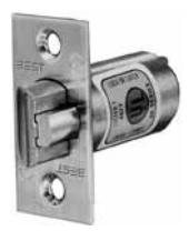
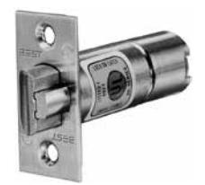
8KL3 Deadlocking Latch
Bolt throw – 9/16"
Backset – 2 3/4"
Front – 2 1/4" x 1 1/8" beveled.
Tube – To fit 1" diameter hole in door edge.
To order: (with unit) designate "9K3" on How to Order (page 3).
To order: (without unit) designate "8KL3-SL" (Spring Latch) or DL (Deadlocking Latch) and finish.

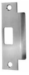
8KS3–7/8 Flat Strike
Dimension: Conforms to ANSI A115.2 for 1 3/4" doors (4 7/8" x 1 7/8" flat)
To order: (with unit) designate "S3-7/8" on How to Order (page 3).
To order: (without unit) designate 8KS3-
7/8 and finish.
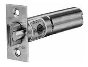
8KL4 Deadlocking Latch
Bolt throw – 9/16"
Backset – 3 3/4"
Front – 2 1/4" x 1 1/8" beveled.
Tube – To fit 1" diameter hole in door edge.
To order: (with unit) designate "9K4" on How to Order (page 3).
To order: (without unit) designate "8KL4-SL" (Spring Latch) or DL (Deadlocking Latch) and finish.
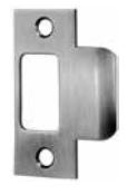
8KS3 Strike
Dimension: Conforms to ANSI A115.2 for 1 3/4" doors (4 7/8" x 1 1/4" with curved lip).
To order: (with unit) designate "S3" on How to Order (page 3).
To order: (without unit) designate 8KS3 and finish.
8KL5 Deadlocking Latch
Bolt throw – 9/16"
Backset – 5"
Front – 2 1/4" x 1 1/8" beveled.
Tube – To fit 1" diameter hole in door edge.
CORMAX™
Patented Keying System
To order: (with unit) designate "9K5" on How to Order (page 3).
To order: (without unit) designate "8KL5-SL" (Spring Latch) or DL (Deadlocking Latch) and finish.
8KS2 Strike (Supplied Standard)
Dimension: Conforms to ANSI A115.2 for 1 3/8" doors (2 3/4" x 1 1/8" with curved lip and box).
To order: (with unit) designate "STK" on How to Order (page 3).
To order: (without unit) designate 8KS2 and finish.

Strikes & Door Preparation
Sample Specification Acceptable Manufacturers
A. Locksets and Latchsets
BEST - No Substitution.
- 1. Locksets and latchsets: ANSI A156.2, Series 4000, Grade 1 UL listed, extra heavy-duty cylindrical type.
- 2. Backset 2 3/4 inches (70mm)
- 3. Interchangeable core 7-pin: [Restricted keyway] [Patented] [Standard] [__________].
- 4. Locksets to have anti-rotational studs that are through-bolted.
- 5. Keyed lever with no exposed keeper hole.
- 6. Each lever to have independent spring mechanism designed to control lever only.
- 7. Outside lever sleeve seamless, 1-piece construction, hardened steel alloy.
- 8. Keyed Lever: Removable only after core is removed, by authorized control key, to allow access to knob keeper
- 9. Hub, side plate, anti-rotational studs 1-piece casting with shrouded locking lug.
B. Keys and Keying
-
A. Cylinders: 7-pin, interchangeable core and keyed into a [New] [Existing] factory registered Grand Masterkey System with a [Standard] [Restricted] [Patented] keyway.
- 1. Acceptable Material: Cylinders as manufactured by BEST.
- B. Provide construction cores and keys during construction period. Construction control and operating keys and cores are not part of permanent keying system or furnished on same keyway (or key section) as permanent keying system.
- C. Permanent Keys and Cores: Prepare permanent cores and keys in accordance with keying schedule. [Stamp with applicable key mark for identification.] [Do not stamp.] [__________].
- D. Provide Grand Masterkeys, Masterkeys and other Security Keys.
-
E. Furnish keys in the following quantities:
- 1. [4] [_______] each Grand Masterkeys.
- 2. [4] [_______] each Masterkeys per set.
- 3. [2] [_______] each Change keys each keyed core.
- 4. [6] [_______] each Construction masterkeys.
- 5. [2] [_______] each Control keys.
- 6. Install permanent cores in locksets.
- F. Return construction cores to [{BEST} factory representative] [Hardware manufacturer's representative].
Service Equipment
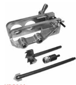
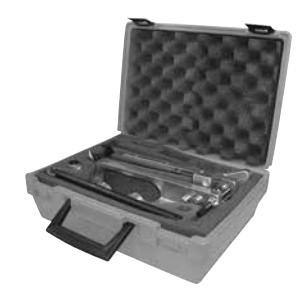
KD304A Boring Jig Kit
The KD304A jig kit is made for boring cut-outs in wooden doors for Fed. Spec. 160 and 161 series cylindrical/tubular locksets, doors 1 3⁄8" to 2 1⁄4" thick. The KD304A kit includes the boring jig (to drill wood doors for 2 3⁄8", 2 3⁄4", 3 3⁄4", and 5" backsets), a quick-release adaptor for 3⁄8" drill chuck, a 2 1⁄8" bit, and a 1" diameter x 9" bit.
The following kit items can also be purchased separately.
KD309 – 2 1⁄8" bit
KD318 – 1" dia. x 9" bit
KD319 – 3⁄8", quick release adaptor
To order complete kits specify:
KD304A Kit
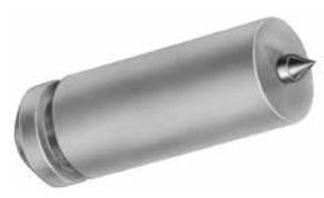
KD312 and KD315 Face Plate Marking Chisel and KD325 Strike Plate Location Pin
The KD315 face plate marking chisel (which locates the mortising for the faceplate) and the KD325 strike locating pin (which centers the strike for proper installation) and is used for Fed. Spec. 161 cylindrical lockset, (1 1/8" x 2 1⁄4"), and BEST® series 82T & 83T tubular locks. The KD312 face plate marking chisel is available for Fed. Spec. 160 (1" x 2 1⁄4" ) preparation
To order specify:
KD312 – face plate marking chisel 1" (160)
KD315 – face plate marking chisel 1 1/8" (161)
KD325 – strike plate locating pin
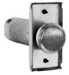
KD303 Through-Bolt Drill Jig
Special accessory jig aids in aligning 5/16" holes for through-bolt mounting. Install the latch first, then insert jig in 2 1/8" bored hole, align with door edge and drill with 5/16" drill bit. To order specify: KD303.
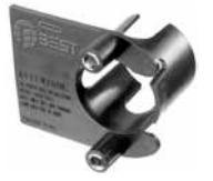
KD317 Spanner Wrench and KD340 Spring Tool
All 9K locksets require the use of KD317 spanner wrench for door removal. This tool is included 1 per every 9 locksets with your order. If more are needed, desnate KD317 on your order. The KD340 lever return spring tool with its unique design feature is used when replacing the 9K lever return spring. To order specify: KD340.

KD315 (Fed. Spec. 161) KD325
KD303-9K
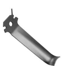
KD317 Spanner Wrench
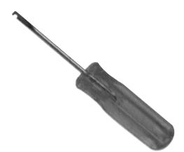
KD340 Spring Tool

6161 East 75th Street Indianapolis, IN 46250 USA
Phone 855-365-2407
bestaccess.com