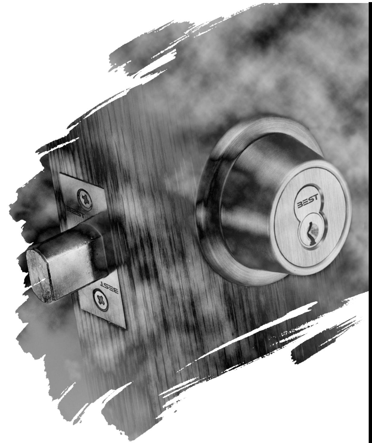
BEST Mechanical Locks 8T Service Manual
Open the original PDF document
View PDF
T SERIES
SERVICE MANUAL

CREDITS/COPYRIGHT
©1996–99, 2002 Best Lock Corporation, dba Best Access Systems. All rights reserved. Printed in the United States of America.
Information in this document is subject to change without notice and does not represent a commitment on the part of Best Access Systems.
This publication is intended to be an accurate description and set of instructions pertaining to its subject matter. However, as with any publication of this complexity, errors or omissions are possible. Please call your BEST distributor or Best Access Systems at (317) 849-2250 if you see any errors or have any questions. No part of this manual and/or databases may be reproduced or transmitted in any form or by any means, electronic or mechanical, including photocopying, recording, or information storage and retrieval systems, for any purpose, without the express written permission of Best Access Systems.
This document is distributed as is, without warranty of any kind, either express or implied, respecting the contents of this manual, including but not limited to implied warranties for the publication's quality, performance, merchantability, or fitness for any particular purpose. Neither Best Access Systems, nor its dealers or distributors shall be liable to the user or any other person or entity with respect to any liability, loss, or damage caused or alleged to be caused directly or indirectly by this publication.
Written and designed at Best Access Systems, 6161 East 75th Street, Indianapolis, Indiana 46250.
T56104 Rev B 1816702 ER7991-6 May 2002
CONTENTS
FIGURES III
GETTING STARTED 1–1 Technical Support 1–1 Support services 1–1 Telephone technical support 1–1 Training seminars 1–1 8T OVERVIEW 2–1 Introduction 2–1 ANSI Standard compliance 2–1 8T Overview 2–2 Lock characteristics 2–2 Function descriptions 2–2 INTERNAL COMPONENTS 3–1 K function—deadbolt thumbturn 3–2 K (cs) function—thumbturn deadbolt with concealed screws 3–3 L function—one-way deadbolt 3–4 L (cs) function—one-way deadbolt with concealed screws 3–5 M function—double cylinder deadbolt 3–6 S function—classroom deadbolt 3–7 S (cs) function—classroom deadbolt with concealed screws 3–8 KL function—one-way turn knob deadbolt 3–9
MISCELLANEOUS PARTS 4–1
Cylinders 4–3
Thick door parts—spacer rings, spindles, and clamp screws 4–4
GLOSSARY 5–1
INDEX 6–1
FIGURES
INTERNAL COMPONENTS
K function exploded diagram—deadbolt operated by outside key or inside thumbturn 3–2
K function with concealed screws exploded diagram—deadbolt operated by outside key or inside thumbturn 3–3
L function exploded diagram—deadbolt operated from one side only 3–4
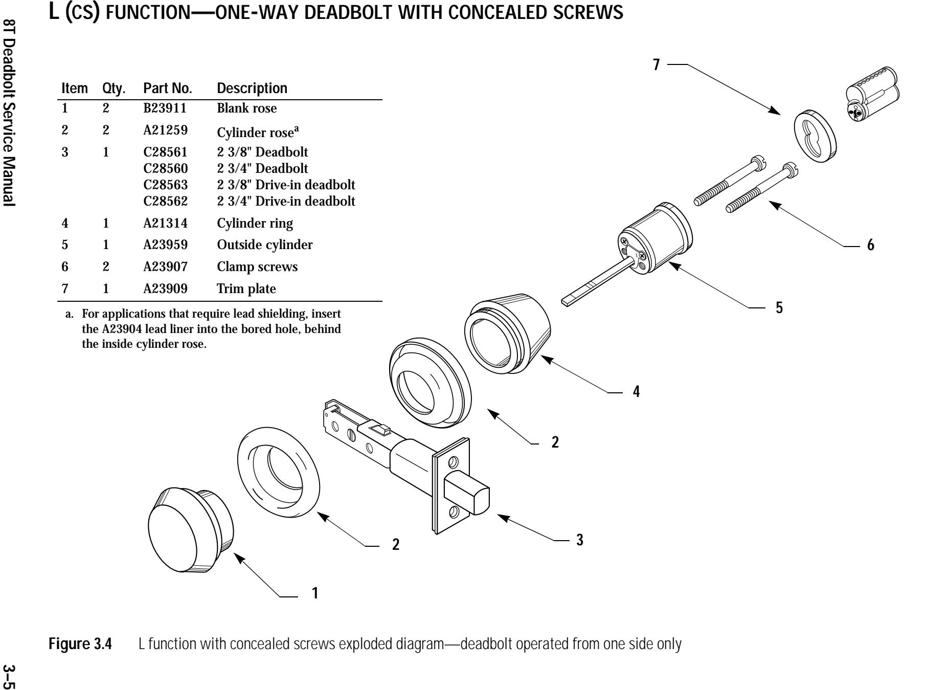
L function with concealed screws exploded diagram—deadbolt operated from one side only 3–5
M function exploded diagram—deadbolt operated from either side—concealed mounting screws are standard. 3–6
S function exploded diagram—deadbolt operated from outside by key. The thumbturn only retracts the deadbolt. 3–7
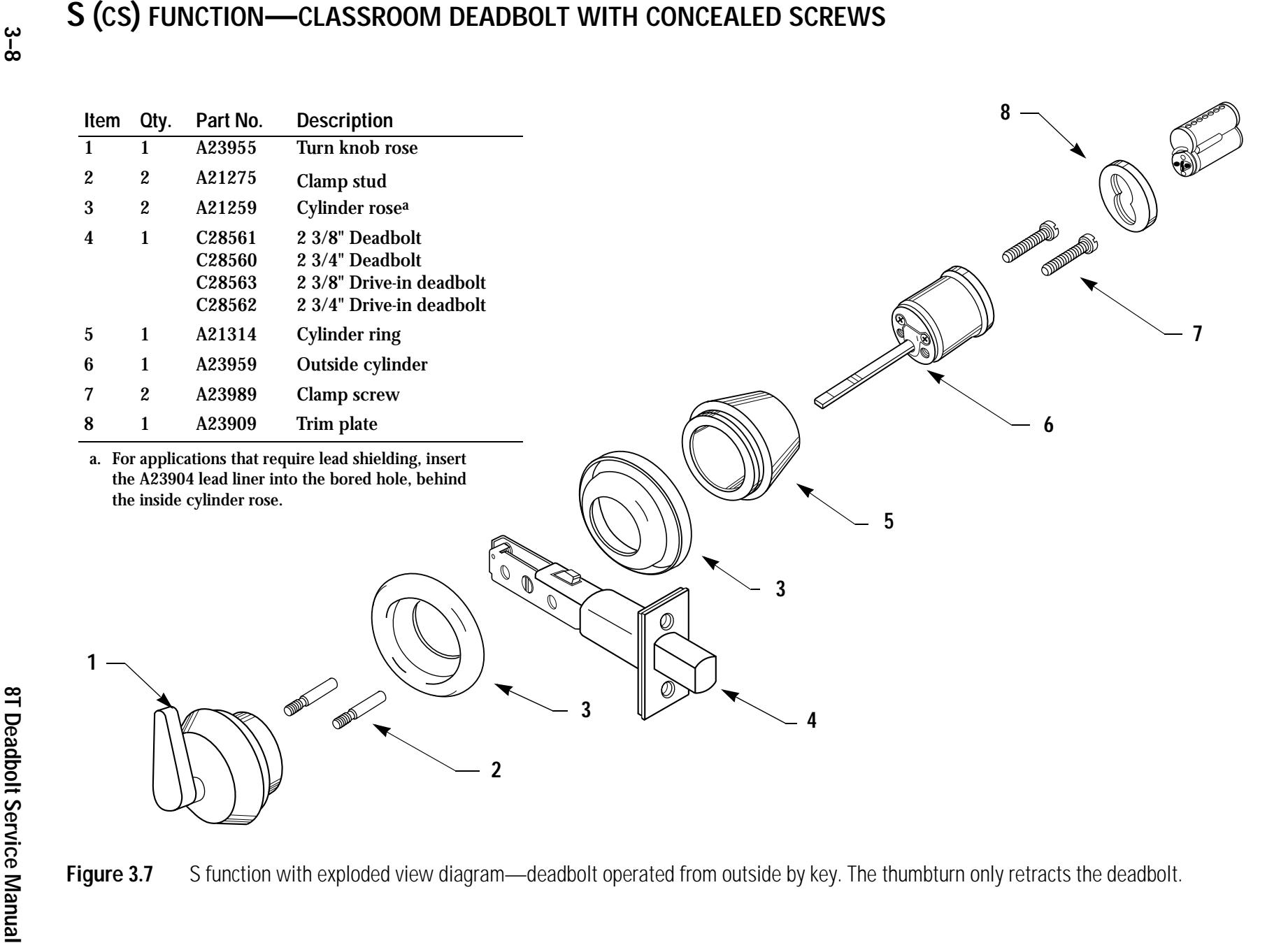
S function with exploded view diagram—deadbolt operated from outside by key. The thumbturn only retracts the deadbolt. 3–8
KL function with exploded view diagram—deadbolt operated by turn knob only. 3–9
MISCELLANEOUS PARTS
Strikes—see the table below for part numbers and descriptions. 4–2 Strike boxes—see the table below for part numbers and descriptions. 4–2 Exploded view of a standard 8T cylinder 4–3
1 GETTING STARTED
The 8T Deadbolt Service Manual contains essential information to help you install and maintain your 8T deadbolt locks.
TECHNICAL SUPPORT
| Support | When you have a problem with the 8T deadbolt | |||
|---|---|---|---|---|
| services | lock, your first resource for help is this 8T Deadbolt | |||
| Service Manual. If you cannot find a satisfactory | ||||
| answer, contact your local BEST Representative. | ||||
| Telephone | Best Access Systems Representatives provide | |
|---|---|---|
| technical | telephone technical support for all products. You | |
| support | may locate the Representative nearest you by calling | |
|
(317)
849-2250 Monday through Friday, between |
||
| 7:00 a.m. and 4:00 p.m. eastern standard time; or | ||
| visit the web page, www.BestAccess.com. | ||
| Training | BEST provides training sessions for its customers. If |
|---|---|
| seminars | interested, contact your local Representative for |
| details. |
2 8T OVERVIEW
INTRODUCTION
The Best 8T Series deadbolt locks meet or exceed the highest operational and security standards in the industry. Every part of the 8T series tubular lock is designed to precise tolerances and is made with the highest quality materials.
This manual covers the installation, operation, and maintenance of the 8T tubular locks. It contains exploded diagrams and part numbers of all internal components and trim components.
ANSI Standard compliance
8T deadbolt locks meet or exceed American National Standard BHMA/ANSI A156.5, Grade 1.
8T OVERVIEW
All 8T deadbolt locks have the following characteristics in common:
Lock characteristics
| Feature | Description |
|---|---|
| Deadbolt | 1" throw, 5/8" x 7/8" bolt |
| Faceplate |
82T: 1" x 2 1/4"
83T: 1 1/8" x 2 1/4" |
| Backset |
82T: 2 3/8"
83T: 2 3/4" |
| Trim |
Wrought brass or bronze cylinder, rose, and thumbturn
rose |
| Door thickness range | 1 3/8" through 3" |
FUNCTION DESCRIPTIONS
The table below summarizes how each of the five deadbolt lock functions operate.
| Diagram | Function | ANSI No. | Fed. No. | Deadbolt operated by |
|---|---|---|---|---|
| K | E2151 | 181K |
Turning the key in the outside
■ cylinder, or Turning the inside turn knob. ■ |
|
| KL | E2191 | N/A |
Turning the inside turn knob.
■ |
|
| L | E2161 | 181L |
Turning the key in the outside
■ cylinder The inside cylinder is blank. |
|
| M | E2141 | 181M |
Turning the key in the inside or
■ outside cylinder. The inside mounting screws are concealed. |
|
| S | E2171 |
Turning the key in the outside
■ cylinder, or Turning the inside turn knob. The ■ turn knob only retracts the deadbolt—it cannot throw the deadbolt. |
3 INTERNAL COMPONENTS
This section diagrams all 8T Series deadbolt exploded views. These diagrams detail all available replacement parts. To find a replacement part, first identify the lock function in question. Then identify the part you need and find its corresponding part number on the same page. For more information on 8T functions, see page 2–2.
I
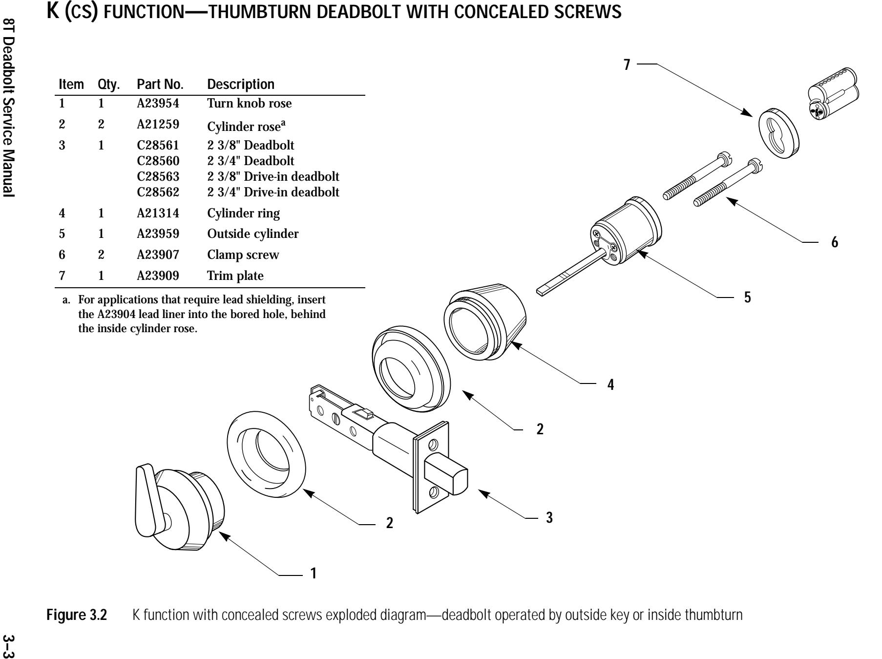
K FUNCTION—DEADBOLTTHUMBTURN
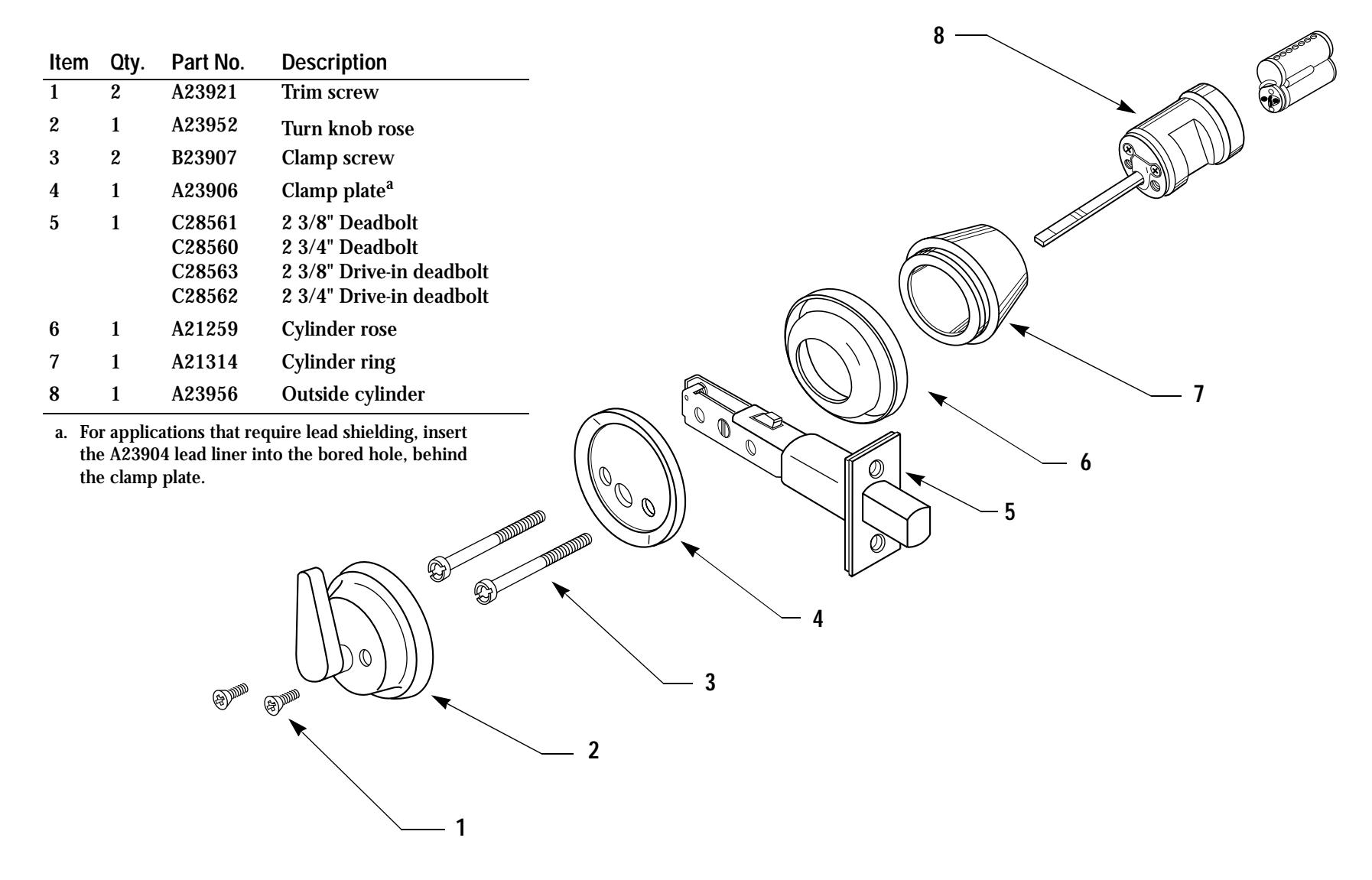
Figure 3.1 K function exploded diagram—deadbolt operated by outside key or inside thumbturn
3–4
L FUNCTION—ONE-WAYDEADBOLT
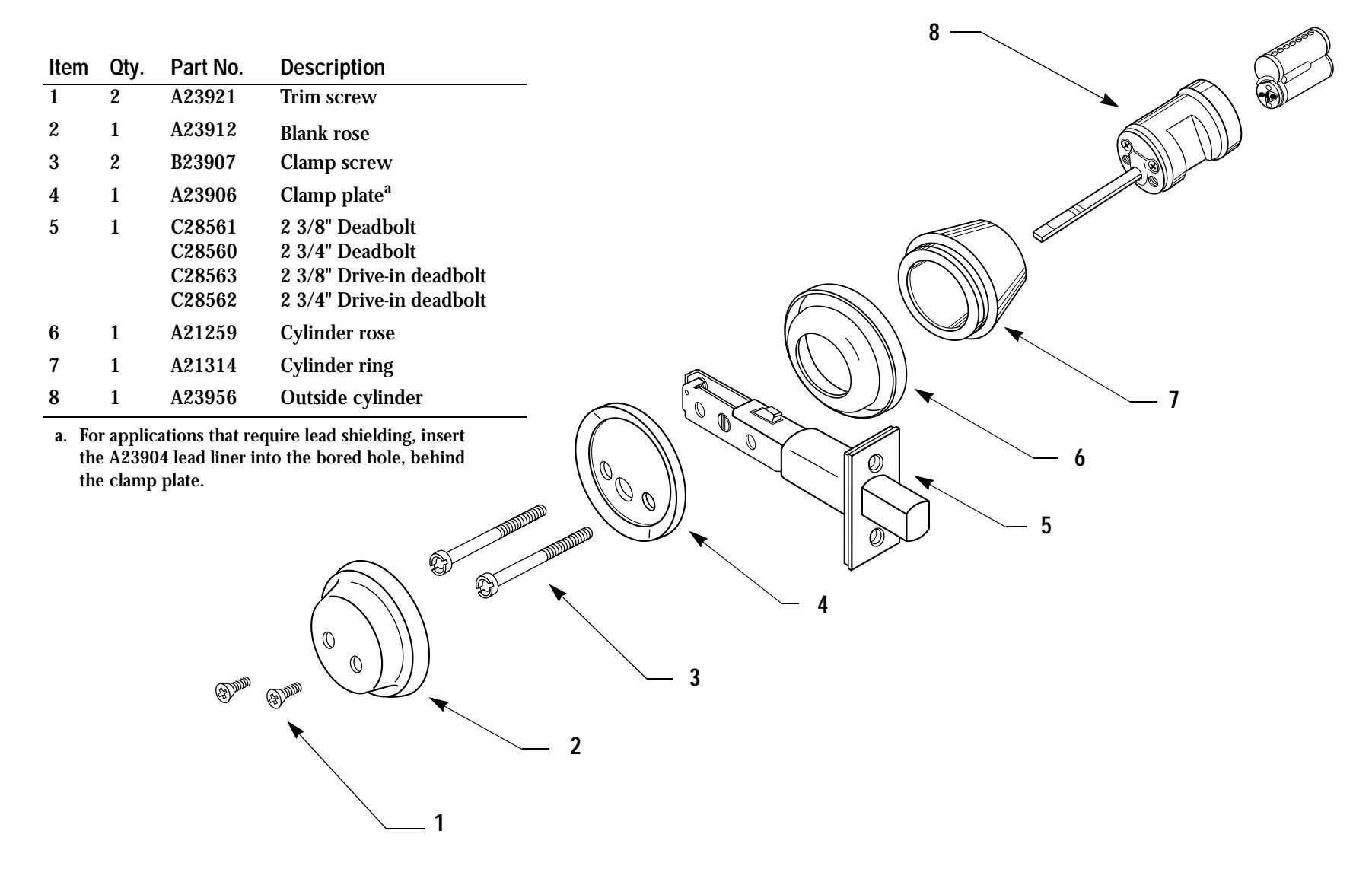
Figure 3.3 L function exploded diagram—deadbolt operated from one side only
M FUNCTION—DOUBLE CYLINDER DEADBOLT
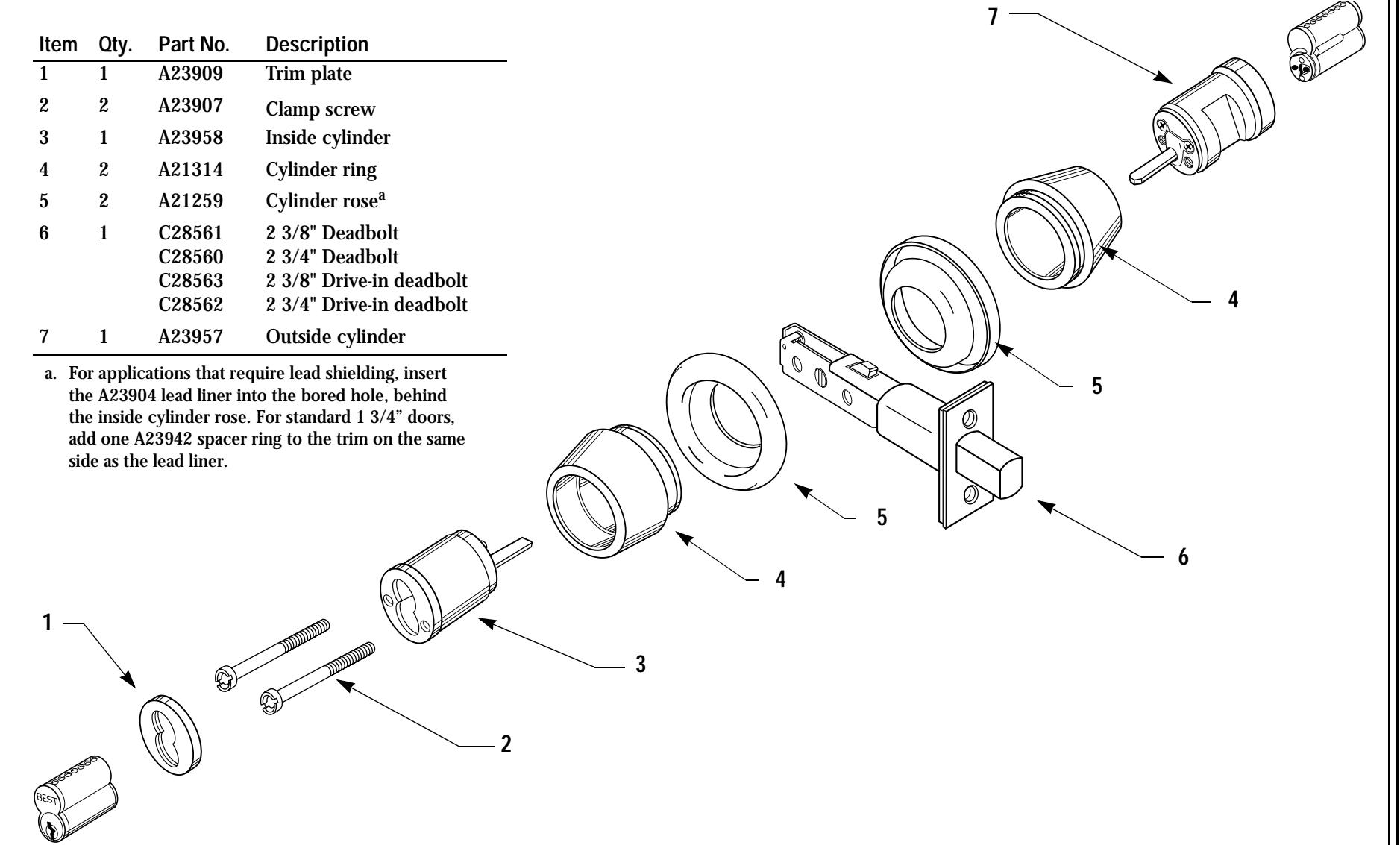
Figure 3.5 M function exploded diagram—deadbolt operated from either side—concealed mounting screws are standard.
ts
S FUNCTION—CLASSROOMDEADBOLT
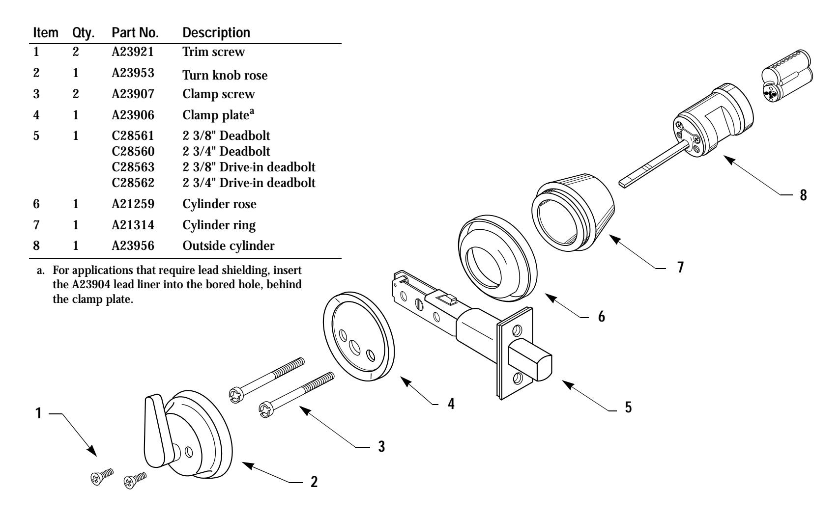
Figure 3.6 S function exploded diagram—deadbolt operated from outside by key. The thumbturn only retracts the deadbolt.
3–8
KL FUNCTION—ONE-WAY TURN KNOB DEADBOLT
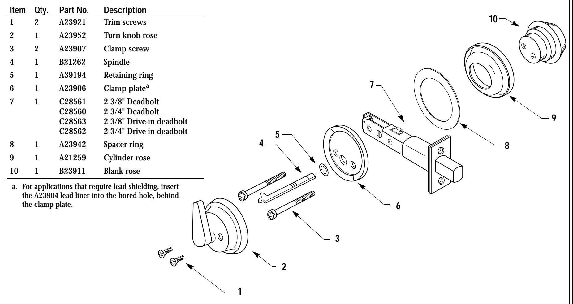
Figure 3.8 KL function with exploded view diagram—deadbolt operated by turn knob only.
4 MISCELLANEOUS PARTS
The following pages list all miscellaneous parts for the 8T deadbolt. These parts consist of strikes, strike boxes, screws, cylinder parts, and thick door parts.
STRIKES AND STRIKE BOXES
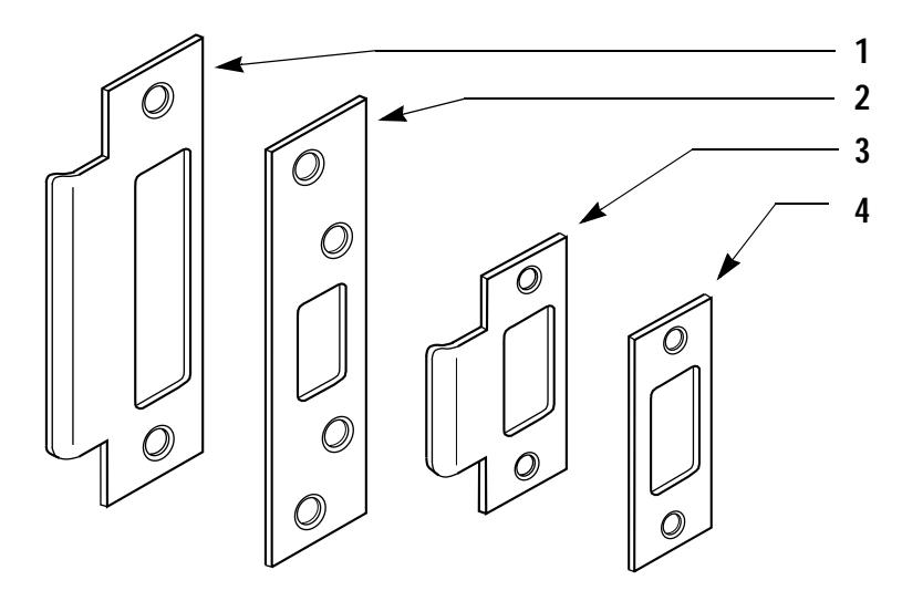
Figure 4.1 Strikes—see the table below for part numbers and descriptions.
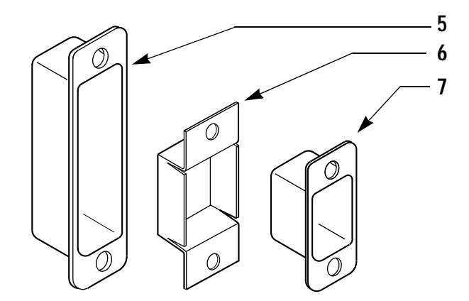
Figure 4.2 Strike boxes—see the table below for part numbers and descriptions.
| Item |
Nom–
enclature |
Description | Screw part no.a |
Corresponding
strike box no. |
|---|---|---|---|---|
| 1 | 8TS1 | ANSI deadbolt strike | A18724 | B34380 |
| 2 | 8TS5 | High security deadbolt strike | A28523b | B34380 |
| 3 | 8TS4 | Lip deadbolt strike | A25359 | B24026 |
| 4 | 8TSTK | Standard deadbolt strike | A25359 | B24026 |
| 5 | 30HS4 | ANSI strike box—plastic | N/A | N/A |
| 6 | 8KS1 | Standard strike box—metal | N/A | N/A |
| 7 | B24026 | Standard strike box—plastic | N/A | N/A |
a. Two screws are supplied with every strike unless otherwise noted.
b. The 8TS5 uses four (4) screws.
CYLINDERS
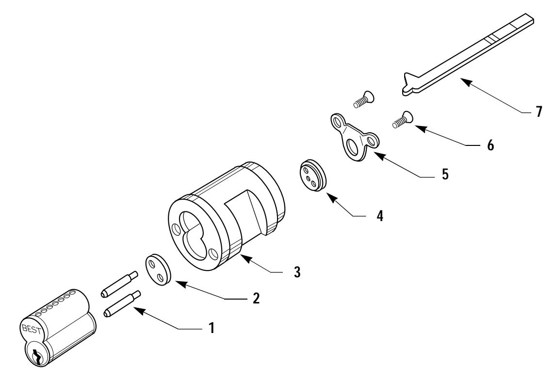
Figure 4.3 Exploded view of a standard 8T cylinder
| Item | Qty. | Part no. | Description |
|---|---|---|---|
| 1 | 2 | A10470 | Throw pin |
| 2 | 1 | A10390 | Spacera |
| 3 | 1 | C23901 | Cylinder housing |
| 4 | 1 | A28521 | Throw plug |
| 5 | 1 | A20941 | Retainer |
| 6 | 2 | A14553 | Retainer screw |
| 7 | 1 | A21262 | Standard spindleb |
a. To rivet the throw member parts to the cylinder, use the ED212 mortise tool.
b. For the M function use the A21264 spindle. See the thick door chart on page 4–4 for more information about various length spindles.
THICK DOOR PARTS—SPACER RINGS, SPINDLES, AND CLAMP SCREWS
When retrofitting a tubular deadbolt to a non-standard door thickness, two parts vary in length to accommodate the additional thickness. These parts are the spindle and the clamp screws. To find the correct parts for the door thickness, follow the table below.
| Door | |||||||||
|---|---|---|---|---|---|---|---|---|---|
| Part | thickness | K | K(cs) | L | L(cs) | M | S | S(cs) | KL |
| Spacer ring | 1 3/8"a | A23942 | A23942 | A23942 | A23942 | A23942b | A23942 | A23942 | A23942 |
| 1 3/4" | A23942c | A23942 | |||||||
| Spindle | 1 3/8" | A21262 | A21262 | A21262 | A21262 | A21263d | A21262 | A21262 | A21262 |
| 1 3/4" | A21262 | A21262 | A21262 | A21262 | A21264d | A21262 | A21262 | A21262 | |
| 2" | A21262 | A21262 | A21262 | A21262 | A21264d | A21262 | A21262 | A21262 | |
| 2 1/4" | A21262 | A21262 | A21262 | A21262 | A21288d | A21262 | A21262 | A21262 | |
| 2 1/2" | A21262 | A21262 | A21262 | A21262 | A21288d | A21262 | A21262 | A21262 | |
| 2 3/4" | A21262 | A21262 | A21262 | A21262 | A21289d | A21262 | A21262 | A21262 | |
| 3" | A24053 | A24053 | A24053 | A24053 | A21289d | A24053 | A24053 | A24053 | |
| Clamp | 1 3/8" | B23907 | B23907 | B23907 | B23907 | B23907 | B23907 | A23988 | B23950 |
| screwe | 1–3/4" | B23907 | B23907 | B23907 | B23907 | B23907 | B23907 | A23989 | B23907 |
| 2" | B23907 | B61412 | B23907 | B61412 | B61412 | B23907 | A24055 | B23907 | |
| 2 1/4" | B61413 | B61413 | B61413 | B61413 | B61413 | B61413 | A24056 | B61412 | |
| 2 1/2" | B61414 | B61414 | B61414 | B61414 | B61414 | B61414 | A24057 | B61413 | |
| 2 3/4" | B23985 | B23985 | B23985 | B23985 | B23985 | B23985 | A24058 | B61414 | |
| 3" | B61415 | B61415 | B61415 | B61415 | B61415 | B61415 | A24059 | B23985 |
a. The lead liner (A23904) is available on all functions in all door thicknesses except the narrow 1 3/8" thick door.
b. For the M function, use two spacer rings on 1 3/8" thick doors.
c. For the M function with lead liner on standard 1 3/4" thick doors, add one spacer ring on the same trim side as the lead liner.
d. Use two spindles on all M functions.
e. Use two clamp screws on all functions.
5 GLOSSARY
Auxiliary lock A lock having a latchbolt or deadbolt operated by a key or
a thumbturn or both. This type of lock is often used in conjunction with another lock which may or may not be key operated, but has a latchbolt operated by knobs or
levers.
Bored deadlock A lock that fits round, bored holes drilled into the face
and edge of a door. Bored deadlocks have a deadbolt
operated by a key or thumbturn or both.
Chassis The internal frame of the lock.
Deadbolt lock A lock having a bolt whose end protrudes from and
retracts into, the lock front. When the door is closed and the deadbolt thrown, the deadbolt extends into a hole provided in the strike, locks the door, and does not
retract when pressure is applied to the end.
Drive-in deadbolt A deadbolt that is installed by hammering it into the edge
of the door.
Hand of door The swing direction of the door as viewed from the
outside of the door. A right-handed (RH) door is hinged on the right and swings inward. A left-handed (LH) door is hinged on the left and swings inward. If either of these doors swing outward, it becomes a right-hand reverse bevel (RHRB) door, or a left-hand reverse bevel (LHRB)
door, respectively.
Spindle A bar that projects from the back of a cylinder that
engages the lock mechanism. When the spindle is rotated by the key or thumbturn, it either locks or unlocks the
lock. Also called "tailpiece."
Strike A plate fastened to the door frame that the bolt projects into.
Strike box A housing used in back of a strike to enclose the bolt or bolt openings.
Thumbturn The component that projects or retracts a deadbolt operated by grasping and
turning. Also called "turn knob" or "turnpiece."
Tubular The shape (tube-like) of the lock chassis and bolt enclosure.
6 INDEX
| A | function descriptions 2–2 |
|---|---|
| ANSI Numbers, as function description 2–2 | functions 2–2 |
| ANSI, compliance with 2–1 | G |
| B | grade, of security 2–1 |
| boxes, of strikes 4–2 | I |
| C | internal components 3–1 |
|
clamp screws 4–4
components, internal 3–1 cylinders, parts of 4–3 |
K
K function with concealed screws, exploded |
|
D
deadbolt throw length 2–2 |
diagram of 3–3
K function, exploded diagram of 3–2 KL function, exploded diagram of 3–9 |
|
descriptions of functions 2–2
diagrams |
L |
|
of function descriptions 2–2
Door thickness range 2–2 |
L function with concealed screws, exploded
diagram of 3–5 |
| E |
L function, exploded diagram of 3–4
length, of deadbolt throw 2–2 |
|
exploded diagrams
K function 3–2 K function with concealed screws 3–3 |
lock dimensions
of backset 2–2 of faceplate 2–2 |
|
KL function 3–9
L function 3–4 |
M |
|
L function concealed screws 3–5
M function 3–6 |
M function, exploded diagram of 3–6
miscellaneous parts 4–1 |
|
S function 3–7
S function with concealed screws 3–8 |
cylinders 4–3
strike boxes 4–2 strikes 4–2 |
| F | thick door parts 4–4 |
|
Federal numbers, as function descriptions
2–2 |
8T Deadbolt User Manual 6-1
6-2
Ρ parts clamp screws 4-4 cylinders 4-3 miscellaneous 4-1 spindles 4-4 strike boxes 4–2 strikes 4-2 thick door 4-4 parts breakdown 3-1 S S function with concealed screws, exploded diagram of 3-8 S function, exploded diagram of 3screws, of clamp 4-4 security grade 2-1 see page 2-2 3-1 spindles 4-4 strike boxes 4-2 strikes 4-2 support services Telephone technical support 1-1 Т thick door parts 4-4 thicknesses, valid range 2-2 throw length 2-2 training seminars 1–1
8T Deadbolt User Manual

A INSTALLATION INSTRUCTIONS
The following pages contains the Installation Instructions for 82T – 83T Deadbolt Locks .

Installation Instructions for 82T–83T Deadbolt Locks
1 Center punch the drill points
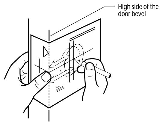
Figure 1 Positioning and marking with the template
- 1 Place the template at the desired height, on the high side of the door bevel.
- 2 Tape the template to the door.
- 3 Center punch the drill points.
2 Bore two holes
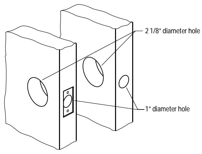
Figure 2 Holes for standard and drive-in deadbolts
- 1 Bore a 2 1/8" diameter hole. To avoid splintering a wood door, bore the hole from both sides of the door.
- 2 Drill a 1" diameter hole from the edge of the door that intersects the 2 1/8" hole.
For deadbolts with faceplates
■ Using the deadbolt faceplate as a guide, mortise the edge of the door to recess the faceplate.
3 Install strike plate
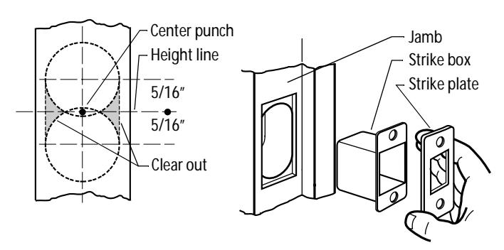
Figure 3 Installing the strike
- 1 Center punch the jamb directly opposite the bolt hole in the door. See Figure 3.
- 2 Drill two 1" diameter holes, located 5/16" above and below the center punch to a depth of 1 1/8".
Note: For S1 strike plates only, drill two additional 1" diameter holes located 15/16" above and below the center punch. Clear out the material between the holes.
3 Using the strike as a guide, mortise the jamb and install the strike box and strike plate as shown in Figure 3.
4 Install deadbolt assembly
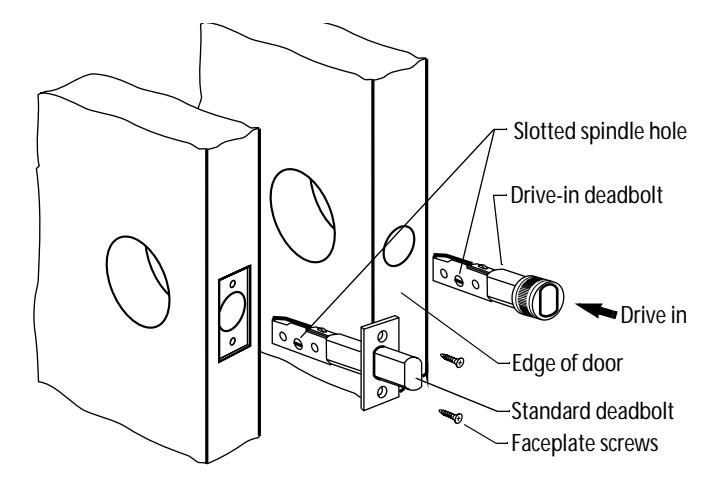
Figure 4 Installing the standard and drive-in deadbolts
For standard deadbolts
- 1 Insert the standard deadbolt with the slotted spindle hole at the bottom of the assembly as shown in Figure 4.
- 2 Secure the standard deadbolt to the door with the faceplate screws.
For drive-in deadbolts
- 1 Make sure the drive-in deadbolt is in the retracted position.
- 2 Insert the deadbolt into the door with the slotted hole at the bottom of the assembly. See Figure 4.
3 Using a hammer and wooden block, lightly drive the deadbolt into the hole until the face of the deadbolt is flush with the edge of the door.

5 Install cylinder or cylinders
For 1 3/8" thick doors only
■ Slip the spacer ring behind the outside cylinder and trim assembly as shown in Figure 5.
Note: Use two spacer rings for M function deadbolts, one behind the outside cylinder and the other behind the inside cylinder.
For single-keyed cylinder deadbolts except 'S' (classroom) functions
- 1 Extend the bolt with a screwdriver.
- 2 Install the cylinder and trim assembly with the spindle in the vertical position as shown in Figure 5.
For non-keyed KL functions
- 1 Extend the bolt with a screwdriver.
- 2 Slip the spacer ring behind the outside rose.
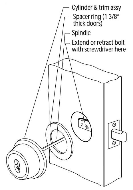
Figure 5 Installing the cylinder and trim assembly
For 'S' (classroom) function deadbolts
- 1 Retract the deadbolt with a screwdriver.
- 2 Install the cylinder and trim assembly with the spindle in the horizontal position.
For double-keyed cylinder deadbolts ('M' function)
1 Extend the bolt with a screwdriver.
2 Install each cylinder with its ring and rose as shown in Figure 6.
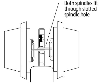
Figure 6 Side view of a double-keyed deadbolt
6 Attach inside trim
For standard mounting screws
1 Secure the cylinder to the door with the clamp plate and mounting screws as shown in Figure 7.
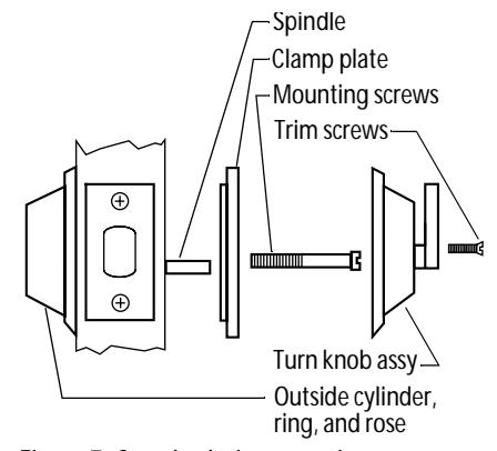
Figure 7 Standard trim mounting
- 2 Break the spindle at the appropriate notch to suit the installation.
- 3 Slide the turn knob assembly over the spindle and secure it with the trim screws supplied.
For concealed mounting screws
1 With the inside rose and turn knob unit in place, put the two mounting screws through the outside cylinder as shown in Figure 8.
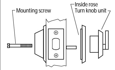
Figure 8 Concealed trim mounting
BEST ACCESS SYSTEMS
Indianapolis, Indiana
- 2 Break the spindle at the appropriate notch to suit the installation.
- 3 Screw the mounting screws into the back of the turn knob unit.
7 Install core or cores
For double-keyed deadbolts or deadbolts with concealed screws
■ To cover the mounting screw holes, put the cylinder face into the ring. See Figure 9.
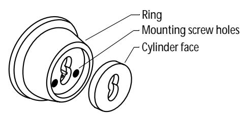
Figure 9 Installing the cylinder face for doublekeyed deadbolts and deadbolts with concealed screws
For all deadbolt locks
1 Put the control key into the core and turn the key 15 degrees clockwise as shown in Figure 10.
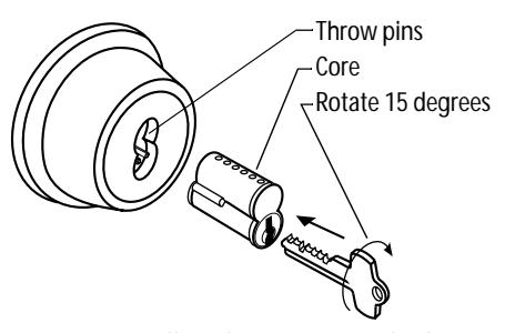
Figure 10 Installing the core on standard deadbolts
- 2 Adjust the throw pins if needed, then put the core into the cylinder with the control key.
- 3 Turn the key 15 degrees counterclockwise and remove the key.
Caution: Locks that secure both sides of the door are controlled by building codes and the Life Safety Code®. In an emergency exit situation, failure to quickly unlock the door from the inside could be hazardous or even fatal.
Patents
Products are covered by one or more of the following patents:
U.S. Patents
D290085, 4444034, 4424693, 4386510, 4294093, 4301667, 4655063, 4843852
Other patents pending.