BEST Mechanical Locks 6K Series Service Manual
Open the original PDF document
View PDF

6K SERIES
SERVICE MANUAL

CREDITS/COPYRIGHT
Copyright © 2000–2004 Stanley Security Solutions, Inc. and Stanley Logistics, Inc. All rights reserved. Printed in the United States of America.
Information in this document is subject to change without notice and does not represent a commitment on the part of Stanley Security Solutions, Inc. The software described in this document are furnished under a license agreement or nondisclosure agreement.
This publication is intended to be an accurate description and set of instructions pertaining to its subject matter. However, as with any publication of this complexity, errors or omissions are possible. Please call your BEST® distributor or Stanley Security Solutions, Inc., Best Access Systems at (317) 849-2250 if you see any errors or have any questions. No part of this manual and/or databases may be reproduced or transmitted in any form or by any means, electronic or mechanical, including photocopying, recording, or information storage and retrieval systems, for any purpose, without the express written permission of Stanley Security Solutions, Inc.
This document is distributed as is, without warranty of any kind, either express or implied, respecting the contents of this book, including but not limited to implied warranties for the publication's quality, performance, merchantability, or fitness for any particular purpose. Neither Stanley Security Solutions, Inc., nor its dealers or distributors shall be liable to the user or any other person or entity with respect to any liability, loss, or damage caused or alleged to be caused directly or indirectly by this publication.
Written and designed by Stanley Security Solutions, Inc. and Avalon Group, Inc., Indianapolis, Indiana.
T56080 Rev C 1798060 ER-7991-6 November 2004
CONTENTS
FIGURES VII
GETTING STARTED 1–1
Introduction 1–1
Certifications and standards 1–1
Documentation package 1–1
Technical support 1–2
    Support services 1–2
    Telephone technical support 1–2
FUNCTIONS AND PARTS LISTS 2–1
Function descriptions 2–2
    Single-keyed functions 2–2
    Non-keyed functions 2–4
    Special functions 2–5
    Functions by ANSI designation 2–5
Exploded diagrams and parts lists 2–6
    AB function—entrance lock (ANSI F109) 2–6
    B function—entrance lock (ANSI F82) 2–7
    D function—storeroom lock (ANSI F86) 2–8
    E function—service station lock (ANSI F92) 2–9
    L function—privacy lock (ANSI F76) 2–10
    LL function—hospital privacy 2–11
    N function—passage lock (ANSI F75) 2–12
    P function—patio lock (ANSI F77) 2–13
    R function—classroom lock (ANSI F84) 2–14
    Y function—exit lock 2–15
|
Function conversion
2–16 |
|---|
|
Trim parts
2–17 |
|
Strikes and strike boxes
2–17 |
|
Roses and rose liners
2–18 |
|
Knobs and throw member
2–19 |
|
Dummy trim
2–20 |
|
Latches and latch tube sleeve
2–21 |
|
Tools
2–22 |
|
SERVICE
AND MAINTENANCE 3–1 |
|
Replacing parts
3–2 |
|
Replacing the core and throw member
3–2 |
|
Replacing the knob
3–3 |
|
Replacing the button assembly
3–4 |
|
Replacing the bearing
3–6 |
|
Replacing the inside rose and rose liner
3–7 |
|
Replacing the outside rose and liner assembly
3–8 |
|
Replacing the lock chassis assembly
3–9 |
|
Lubricating the core
3–10 |
|
Aligning the chassis and trim
3–11 |
|
Troubleshooting
3–12 |
|
INSTALLATION INSTRUCTIONS
A–1 |
INDEX B–1
FIGURES
FUNCTIONS AND PARTS LISTS
Understanding function drawings 2–2 Strikes and strike boxes 2–17 Roses and rose liners 2–18 Knobs 2–19 Throw member and spacer 2–19 Dummy trim parts 2–20 Latches 2–21 Latch tube sleeve 2–22 Installation tools 2–22 Boring jig kit 2–23
SERVICE AND MAINTENANCE
Removing and reinstalling the core 3–2 Removing the knob 3–3 Reinstalling the non-keyed knob 3–3 Reinstalling the keyed knob 3–4 Removing the button assembly 3–4 Reinstalling the outside button assembly 3–5 Reinstalling the inside button assembly 3–5 Removing the bearing 3–6 Reinstalling the bearing 3–6 Removing the inside rose and rose liner 3–7 Reinstalling the inside rose and rose liner 3–8 Removing the outside rose and liner assembly 3–8
Reinstalling the outside rose and liner assembly 3–9 Engaging the retractor in the latch 3–10 Engaging the retractor in the latch 3–11
1 GETTING STARTED
INTRODUCTION
The 6K Series Service Manual contains essential information to help you maintain your 6K Series Lock.
CERTIFICATIONS AND STANDARDS
- The locks comply with ANSI A156.2, Series 4000 Grade 2 standards.
- The locks are listed by Underwriter's Laboratories for use on 3 Hr., A label single swinging doors (4¥ x 8¥).
- The 8KS3 strike fits the standard door frame cutout as specified in ANSI A115.2.
DOCUMENTATION PACKAGE
The following documentation is available to help you with the installation, start-up, and maintenance of your 6K Series Lock.
The installation and assembly instructions also can be ordered separately:
| Document Title | Doc. No. |
|---|---|
| Installation Instructions for 6K Cylindrical Locks† | T56061 |
| Installation Instructions for 6K Dummy Trim | T80943 |
†. These installation instructions are included in this manual. See Installation Instructions on page A–1.
The templates required for lock installations also can be ordered separately:
| Document Title | Doc. No. |
|---|---|
|
K01 Template for Door and Frame Preparation for
62K Locks with Small (STK) Strike |
T56050 |
|
K07 Template for Door and Frame Preparation for
62K Locks with Large (S3) Strike |
T56051 |
|
K08 Template for Door and Frame Preparation for
63K, 73KC, 83K & 93K Locks with Small (STK) Strike |
T56052 |
|
K09 Template for Door and Frame Preparation for
63K, 73KC, 83K & 93K Locks with Large (S3) Strike |
T56053 |
|
K10 Template for Door and Frame Preparation
for 64K, 84K & 94K Locks with Small (STK) Strike |
T56054 |
|
K11 Template for Door and Frame Preparation
for 64K, 84K, 94K Locks with Large (S3) Strike |
T56055 |
|
K12 Template for Door and Frame Preparation 65K,
85K & 95K Locks with Small (STK) Strike |
T56056 |
|
K13 Template for Door and Frame Preparation for
65K, 85K & 95K Locks with Large (S3) Strike |
T56057 |
| Template for 6K Dummy Trim | T80944 |
TECHNICAL SUPPORT
Support services
When you have a question about the 6K Series Lock, your first resource for help is the 6K Series Service Manual . If you cannot find a satisfactory answer, contact your local BEST Representative.
Telephone technical support
A factory-trained Certified Product Specialist (CPS) is available in your area whenever you need help. Before you call, however, please make sure that the product is in your immediate vicinity, and that you are prepared to give the following information:
- what happened and what you were doing when the problem arose
- what you have done so far to correct the problem.
Best Access Systems Representatives provide telephone technical support for all 6K Series products. You may locate the representative nearest you by calling (317) 849-2250 Monday through Friday, between 7:00 a.m. and 4:00 p.m. eastern standard time; or visit the web page, www.BestAccess.com.
2 FUNCTIONS AND PARTS LISTS
The following pages contain function descriptions for all 6K Series Locks. This chapter also includes exploded diagrams that show all field serviceable mechanical parts, diagrams of trim and other miscellaneous parts, and function conversion information.
FUNCTION DESCRIPTIONS
This section includes function descriptions grouped by the following function types:
- single-keyed ( page 2–2 )
- non-keyed (page 2–4 )
- special (page 2–5)
- ANSI designation ( page 2–5) .
Note: If the function is ANSI defined, the ANSI designation appears by the function name.
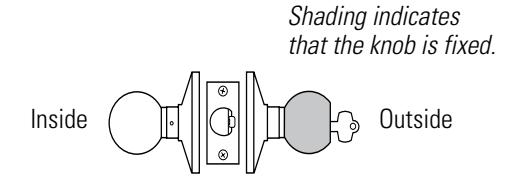
Figure 2.1 Understanding function drawings
Single-keyed functions
The following lists describe how the latchbolt, outside knob, and inside knob operate for each single-keyed 6K function.
AB–Entrance (ANSI F109) D–Storeroom (ANSI F86)
Latchbolt operated by:
- inside knob
- outside key
- outside knob when the inside button is in the unlocked position
Outside knob locked by:
- inside button when pushed in
- inside button when pushed in and rotated clockwise
Outside knob unlocked by:
- inside knob when the inside button is pushed in but not rotated
- outside key when the inside button is pushed in but not rotated
- closing the door when the inside button is pushed in but not rotated
Inside knob is always unlocked
Latchbolt operated by:
- inside knob
- outside key
Outside knob is always fixed Inside knob is always unlocked
E–Service station (ANSI F92) R–Classroom (ANSI F84)
Latchbolt operated by:
- inside knob
- outside key
- outside knob when the inside button is in the unlocked position
Outside knob locked by:
- inside slotted button
- inside slotted button when pushed in and rotated clockwise
Outside knob unlocked by:
- inside knob
- inside slotted button when rotated counterclockwise
- outside key
- closing the door when the inside button is pushed in but not rotated
Inside knob is always unlocked
Latchbolt operated by:
- inside knob
- outside key
- outside knob when not locked
Outside knob locked by:
■ outside key
Outside knob unlocked by:
■ outside key
Inside knob is always unlocked
Non-keyed functions
The following lists describe how the latchbolt, outside knob, and inside knob operate for each non-keyed 6K function.
L–Privacy (ANSI F76) N–Passage (ANSI F75)
Latchbolt operated by:
- inside knob
- outside knob when the inside button is in the unlocked position
Outside knob locked by:
■ inside button
Outside knob unlocked by:
- inside knob
- outside slotted button when pushed in and rotated counterclockwise
- closing the door Inside knob is always unlocked
Latchbolt operated by:
- inside knob
- outside knob
Outside knob is always unlocked Inside knob is always unlocked
Latchbolt operated by:
■ inside knob
Inside knob is always unlocked
Y–Exit P–Patio (ANSI F77)
Latchbolt operated by:
- inside knob
- outside knob when the inside button is in the unlocked position
Outside knob locked by:
■ inside button
Outside knob unlocked by:
- inside knob
- closing the door
Inside knob is always unlocked
1DT–Single dummy trim
This lock is a single, surface-mounted knob for an inactive door or a non-latching door.
Special functions The following lists describe how the latchbolt, outside knob, and inside knob operate for each special 6K function.
LL–Hospital privacy B-Office
Latchbolt operated by:
- inside knob
- outside knob when not locked
Outside knob locked by:
■ inside button
Outside knob unlocked by:
- inside knob
- outside button when pushed in and rotated counterclockwise
- closing the door
Inside knob is always unlocked
Latchbolt operated by:
- inside knob
- outside key
- outside knob when the inside button is in the unlocked position
Outside knob locked by:
■ inside button
Outside knob unlocked by:
- inside knob
- outside key
Inside knob is always unlocked
Functions by ANSI designation
| ANSI No. | Function |
|---|---|
| F75 | N |
| F76 | L |
| F77 | P |
| F82 | B |
| F84 | R |
| F86 | D |
| F92 | E |
| F109 | AB |
2–6
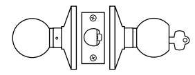
EXPLODED DIAGRAMS AND PARTS LISTS AB FUNCTION—ENTRANCELOCK (ANSI F109)
|
I
te m |
Pa
No t r |
Q
ty |
De
ip io t sc r n |
|||
|---|---|---|---|---|---|---|
| 1 |
(
2– 1 9 ) e p se ag e |
1 |
kn
b Bu tto n o |
|||
| 2 |
A
8 0 0 5 0 |
1 |
Tu
bu b ly tto rn n as se m |
|||
| 3 |
(
2– 1 8 ) se e p ag e |
1 |
Ro
se |
|||
| 4 |
4
A 8 0 0 1 |
2 |
ha
C is ss sc re w |
|||
| 5 |
(
2– 1 8 ) se e p ag e |
1 |
l
Ro in se er |
|||
| 6 |
4
B 8 0 0 8 |
1 |
Be
in ar g |
|||
| 7 |
B
8 0 1 0 5 |
1 |
†
fu ha A B io is t nc n c ss |
|||
| 8 |
(
2– 1 8 ) se e p ag e |
1 |
b
Ro d r l in ly se an os e er as se m |
|||
| 9 |
(
2– 1 9 ) se e p ag e |
1 |
d
kn b Ke y e o |
9 | ||
|
4
3 |
6
5 |
7 | ||||
|
2
1 |
||||||
|
I
i d n s e |
A
B |
Figure 2.2 AB function exploded diagram
B FUNCTION—ENTRANCELOCK (ANSI F82)
|
I
te m |
Pa
No t r |
Q
ty |
De
ip io t sc r n |
|||
|---|---|---|---|---|---|---|
| 1 |
(
2– 1 9 ) se e p ag e |
1 |
kn
Bu b tto n o |
|||
| 2 |
A
5 8 0 0 2 |
1 |
h
bu b ly Pu tto s n as se m |
|||
| 3 |
(
2– 1 8 ) se e p ag e |
1 |
Ro
se |
|||
| 4 |
4
A 8 0 0 1 |
2 |
ha
C is ss sc re w |
|||
| 5 |
(
2– 1 8 ) e p se ag e |
1 |
l
Ro in er se |
|||
| 6 |
4
B 8 0 0 8 |
1 |
Be
in ar g |
|||
| 7 |
B
8 0 1 0 5 |
1 |
†
ha A B fu io is t nc n c ss |
|||
| 8 |
(
2– 1 8 ) se e p ag e |
1 |
d r
l in b ly Ro se an os e er as se m |
9 | ||
| 9 |
(
2– 1 9 ) se e p ag e |
1 |
d
kn b Ke e o y |
|||
|
3
2 |
6
5 4 |
7 | ||||
|
I
i d n s e |
1 | B |
Figure 2.3 B function exploded diagram
2–8
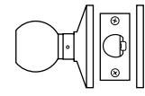
D FUNCTION—STOREROOMLOCK (ANSI F86)
|
I
te m |
Pa
No t r |
Q
ty |
De
ip io t sc r n |
||
|---|---|---|---|---|---|
| 1 |
(
2– 1 9 ) e p se ag e |
1 |
la
kn b P in o |
||
| 2 |
(
2– 1 8 ) e p se ag e |
1 |
Ro
se |
||
| 3 |
4
A 8 0 0 1 |
2 |
C
ha is ss sc re w |
||
| 4 |
(
2– 1 8 ) se e p ag e |
1 |
l
Ro in se er |
||
| 5 |
4
B 8 0 0 8 |
1 |
Be
in ar g |
||
| 6 |
B
8 0 1 0 2 |
1 |
†
fu ha D io is t nc n c ss |
||
| 7 |
(
2– 1 8 ) e p se ag e |
1 |
d r
l b ly Ro in an er m se os e as se |
||
| 8 |
(
2– 1 9 ) e p se ag e |
1 |
d
kn b Ke y e o |
||
|
t
on |
he
ha he ssi fa t t cto c s a |
ry |
3
2 |
7
6 5 4 |
8
O i d t u s e |
|
I
i d n s e |
1 | D |
Figure 2.4 D function exploded diagram
E FUNCTION—SERVICE STATION LOCK (ANSI F92)
| ltem | Part No. | Qty. | Description | |||
|---|---|---|---|---|---|---|
| 1 | (see page 2-19) | 1 | Button knob | |||
| 2 | A80051 | 1 | Slotted button assembly | |||
| 3 | (see page 2-18) | 1 | Rose | |||
| 4 | A80041 | 2 | Chassis screw | |||
| 5 | (see page 2-18) | 1 | Rose liner | |||
| 6 | B80048 | 1 | Bearing | 000 | ||
| 7 | B80105 | 1 | AB function chassis † | |||
| 8 | (see page 2-18) | 1 | Rose and rose liner assembly | |||
| 9 | (see page 2-19) | 1 | Keyed knob | (S | y 9 | |
| 5 | 7 | |||||
| Inside | 1 | E |
Figure 2.5 E function exploded diagram
2–10
L FUNCTION—PRIVACYLOCK (ANSI F76)
|
I
te m |
Pa
No t r |
Q
ty |
De
ip io t sc r n |
|
|---|---|---|---|---|
| 1 |
(
2– 1 9 ) se e p ag e |
1 |
kn
b Bu tto n o |
|
| 2 |
5
A 8 0 0 2 |
1 |
h
bu b ly Pu tto s n as se m |
|
| 3 |
(
2– 1 8 ) e p se ag e |
1 |
Ro
se |
|
| 4 |
4
A 8 0 0 1 |
2 |
ha
C is ss sc re w |
|
| 5 |
(
2– 1 8 ) e p se ag e |
1 |
Ro
l in se er |
|
| 6 |
4
8 0 0 8 B |
2 |
in
Be ar g |
|
| 7 |
1
5 B 8 0 0 |
1 |
†
A fu ha B io is t nc n c ss |
0
1 |
| 8 |
(
2– 1 8 ) se e p ag e |
1 |
d r
l b ly Ro in se an os e er as se m |
|
| 9 |
A
8 0 0 5 3 |
1 |
lo
d bu b ly S tte tto n as se m |
9 |
|
1
0 |
(
2– 1 9 ) e p se ag e |
1 |
kn
b Bu tto n o |
O
i d t s e u |
| 4 | 6 | |||
| 3 |
Figure 2.6 L function exploded diagram
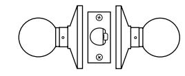
LL FUNCTION—HOSPITALPRIVACY
|
I
te m |
Pa
No t r |
Q
ty |
De
ip io t sc r n |
|
|---|---|---|---|---|
| 1 |
(
2– 1 9 ) se e p ag e |
1 |
kn
b Bu tto n o |
|
| 2 |
A
8 0 0 5 0 |
1 |
h
bu b ly Pu tto n m s as se |
|
| 3 |
(
2– 1 8 ) e p se ag e |
1 |
Ro
se |
|
| 4 |
4
A 8 0 0 1 |
2 |
ha
C is ss sc re w |
|
| 5 |
(
2– 1 8 ) se e p ag e |
1 |
l
Ro in se er |
|
| 6 |
4
B 8 0 0 8 |
2 |
Be
in ar g |
|
| 7 |
5
B 8 0 1 0 |
1 |
†
fu ha A B io is t nc n c ss |
1
0 |
| 8 |
(
2– 1 8 ) e p se ag e |
1 |
d
l b ly Ro in an ro er m se se as se |
9 |
| 9 |
4
A 8 0 0 5 |
1 |
Tu
bu b ly tto rn n m as se |
|
|
1
0 |
(
2– 1 9 ) e p se ag e |
1 |
kn
b Bu tto n o |
O
i d t u s e |
|
4
3 |
7
6 5 |
|||
|
I
i d n s e |
1 | 2 |
L
L |
Figure 2.7 LL function exploded diagram
2–12
N FUNCTION—PASSAGELOCK (ANSI F75)
|
I
te m |
Pa
No t r |
Q
ty |
De
ip io t sc r n |
|||
|---|---|---|---|---|---|---|
| 1 |
(
2– 1 9 ) e p se ag e |
1 |
kn
b P la in o |
|||
| 2 |
(
2– 1 8 ) se e p ag e |
1 |
Ro
se |
|||
| 3 |
4
A 8 0 0 1 |
2 |
C
ha is ss sc re w |
|||
| 4 |
(
2– 1 8 ) se e p ag e |
1 |
l
Ro in se er |
|||
| 5 |
4
B 8 0 0 8 |
2 |
Be
in ar g |
|||
| 6 |
B
8 0 1 7 1 |
1 |
†
fu ha N io is t nc n c ss |
|||
| 7 |
(
2– 1 8 ) e p se ag e |
1 |
d
l b ly Ro in an m se ro se er as se |
|||
| 8 |
(
2– 1 9 ) se e p ag e |
1 |
kn
b P la in o |
8 | ||
|
3
2 |
5
4 |
6 | ||||
|
I
i n s |
d
e |
1 | N |
Figure 2.8 N function exploded diagram
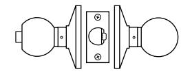
P FUNCTION—PATIOLOCK (ANSI F77)
|
I
te m |
Pa
No t r |
Q
ty |
De
ip io t sc r n |
|
|---|---|---|---|---|
| 1 |
(
2– 1 9 ) e p se ag e |
1 |
kn
b Bu tto n o |
|
| 2 |
A
8 0 0 5 3 |
1 |
h
Pu bu b ly tto s n as se m |
|
| 3 |
(
1 ) 2– 8 se e p ag e |
1 |
Ro
se |
|
| 4 |
4
A 8 0 0 1 |
2 |
ha
C is ss sc re w |
|
| 5 |
(
2– 1 8 ) se e p ag e |
1 |
l
Ro in se er |
|
| 6 |
4
B 8 0 0 8 |
2 |
Be
in ar g |
|
| 7 |
B
8 0 1 0 5 |
1 |
†
fu ha A B io is t nc n c ss |
|
| 8 |
(
2– 1 8 ) e p se ag e |
1 |
d
b Ro l in ly se an ro se er as se m |
9 |
| 9 |
(
2– 1 9 ) se e p ag e |
1 |
la
kn b P in o |
|
|
t
on |
he
ha he fa ssi t t cto c s a |
ry |
6
7 6 5 4 3 2 |
O
i d t u s e |
|
I
i d n s e |
1 | P |
2–14
R FUNCTION—CLASSROOMLOCK (ANSI F84)
Figure 2.10 R function exploded diagram
Y FUNCTION—EXITLOCK
|
I
te m |
Pa
No t r |
Q
ty |
De
ip io t sc r n |
|---|---|---|---|
| 1 |
(
2– 1 9 ) se e p ag e |
1 |
la
kn b P in o |
| 2 |
(
2– 1 8 ) e p se ag e |
1 |
Ro
se |
| 3 |
4
A 8 0 0 1 |
2 |
ha
C is ss sc re w |
| 4 |
(
2– 1 8 ) se e p ag e |
1 |
Ro
l in se er |
| 5 |
4
8 0 0 8 B |
1 |
Be
in ar g |
| 6 |
1
B 8 0 0 7 |
1 |
†
fu ha Y io is t nc n c ss |
| 7 |
4
4 B 5 7 9 |
1 |
fu
b ly Y io t nc n ro se as se m |
|
†
If y ad t on |
ha
lac ing ar e r ep ou a c dit he ha ion ssi to t c s, an he ha he fa ssi t t cto c s a I |
ssi
or s, d i nd ry i d |
4)
de im ri (p mb B8 00 0 in tr art r o ne ng nu er he fin h. Th t b tal led ica is rim ri e i te t e t ng m us ns 7 O i d t u s e 6 5 4 3 2 1 |
|
n
s e |
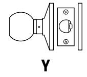
Figure 2.11 Y function exploded diagram
FUNCTION CONVERSION
If you want to convert the function of an existing AB, E, L, or LL 6K Lock, use the following table to determine the parts that you need. Unless otherwise noted, a quantity of one is used for each part.
Compare the column of the function you currently have with the column of the function you need to determine the new parts necessary for conversion. For example, to convert an AB function to an E function, you need an A80051 E button assembly—the only differing part as shown in the table below.
Note: For instructions on replacing the parts listed below, see Replacing parts on page 3–2 .
Standard functions
| Description | E | L | LL | |
|---|---|---|---|---|
| AB button assembly | ■ | |||
| E button assembly | ■ | |||
| L, LL inside button assembly | ■ | ■ | ||
| L outside button assembly | ■ | |||
| LL outside button assembly | ■ | |||
| Button knob | ■ | ■ | ■† | ■† |
| Keyed knob | ■ | ■ | ||
| Bearing | ■ | ■ | ■† | ■† |
| Throw member | ■ | ■ | ||
| AB |
† Requires two.
TRIM PARTS
Strikes and strike boxes
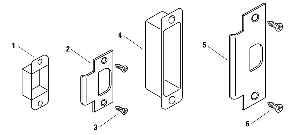
Figure 2.12 Strikes and strike boxes
Standard strikes and strike boxes parts list
| Nomen– | |||
|---|---|---|---|
| Item | clature | Part No. | Description |
| 1 | 8KS1 | B25640 | Standard steel strike box |
| 2 | 6KS2† | A53761 | Standard strike |
| 3 | A25359 | Strike screw | |
| 4 | 30HS4 | B34380 | ANSI plastic strike box |
| 5 | 6KS3‡ | A53773 | ANSI strike |
| 6 | A18724 | Strike screw |
† Includes one A53761 strike, two A25359 strike screws, and one B25640 strike box.
‡ Includes one A53773 strike and two A18724 strike screws.
Roses and rose liners
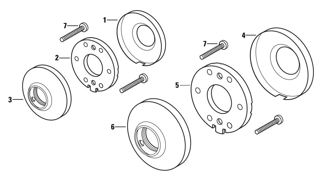
Figure 2.13 Roses and rose liners
Roses and rose liners parts list
| Item | For rose | Part No. | Qty. | Description |
|---|---|---|---|---|
| 1 | C | B80010 | 1 | Small rose |
| 2 | C | C80014 | 1 | Small liner |
| 3 | C | B80108 | 1 | Small outside rose and liner assembly |
| 4 | D | B80009 | 1 | Large rose |
| 5 | D | C80013 | 1 | Large liner |
| 6 | D | B80109 | 1 | Large rose and liner assembly |
| 7 | C & D | A80041 | 2 | Through-bolt screw |
Knobs and throw member
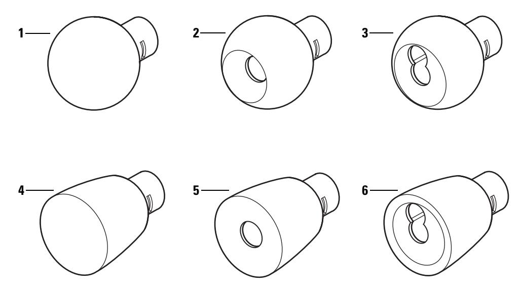
Figure 2.14 Knobs
Knobs parts list
| Style | Item | Part No. | Description |
|---|---|---|---|
| 1 | C80018 | Plain round knob | |
| 4 | 2 | C80017 | Button round knob |
| 3 | B80148 | Keyed round knob | |
| 4 | C80020 | Plain tulip knob | |
| 6 | 5 | C80019 | Button tulip knob |
| 6 | B80151 | Keyed tulip knob |
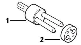
Figure 2.15 Throw member and spacer
Throw member part list
| Item | Part No. | Qty. | Description |
|---|---|---|---|
| 1 | A80170 | 1 | Throw member† |
| 2 | 1882120 | 50 | Spacer |
† For information about cores and keys, see the Core and Key Service Manual .
6K Series Service Manual 2–19
Dummy trim
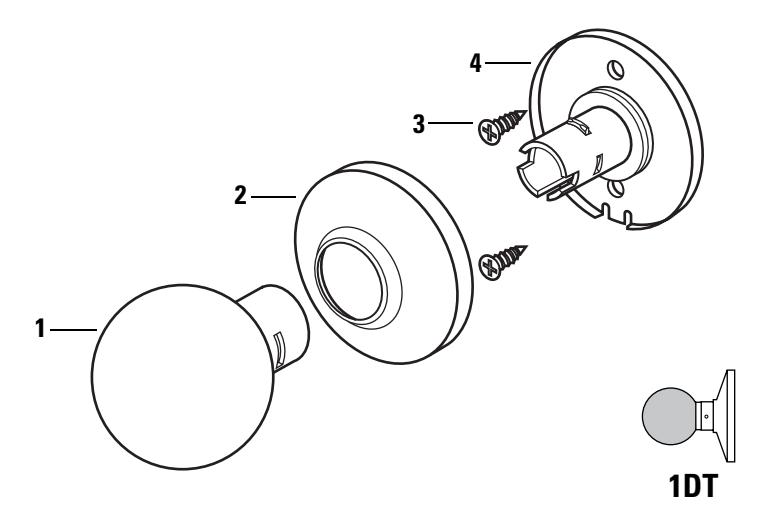
Figure 2.16 Dummy trim parts
Single dummy trim parts list
Note: If you need dummy trim for both sides of the door, order the 2DT.
| Item | Part No. | Qty. | Description |
|---|---|---|---|
| 1 | C80018 | 1 | Round plain knob or |
| not shown | C80020 | 1 | Tulip plain knob |
| 2 | B80024 | 1 | Small rose or |
| not shown | B80023 | 1 | Large rose |
| 3 | A25359 | 2 | Mounting screw |
| 4 | B80119 | 1 | Small hub assembly or |
| not shown | B80118 | 1 | Large hub assembly |
Latches and latch tube sleeve
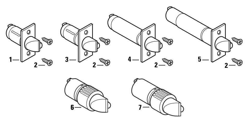
Figure 2.17 Latches
Latches parts list
| Part | Nomen | |||
|---|---|---|---|---|
| Item | No.† | clature | Backset | Description |
| 1 | B80112 | 6KL2-NF‡ | 2 3/8″ | Deadlocking latch with narrow face (1″ ) |
| not shown | B80188 | 6KL2-WF‡ | 2 3/8″ |
Deadlocking latch with wide face
(1 1/8″ ) |
| 2 | A25359 | Latch screw | ||
| 3 | B80189 | 6KL3-NF‡ | 2 3/4″ | Deadlocking latch with narrow face (1″ ) |
| not shown | B80113 | 6KL3-WF‡ | 2 3/4″ |
Deadlocking latch with wide face
(1 1/8″ ) |
| 4 | B80194 | 6KL4-NF‡ | 3 3/4″ | Deadlocking latch with narrow face (1″ ) |
| not shown | B80195 | 6KL4-WF‡ | 3 3/4″ |
Deadlocking latch with wide face
(1 1/8″ ) |
| 5 | B80196 | 6KL5-NF‡ | 5″ | Deadlocking latch with narrow face (1″ ) |
| not shown | B80197 | 6KL5-WF‡ | 5″ |
Deadlocking latch with wide face
(1 1/8″ ) |
| 6 | A80192 | 6KL2-L8 | 2 3/8″ | Drive-in latch |
| 7 | A80193 | 6KL3-L8 | 2 3/4″ | Drive-in latch |
| not shown | B80090 | 2 3/8″ | Semi-automatic latch\ | |
| not shown | B80091 | 2 3/4″ | Semi-automatic latch\ |
† Specify finish.
‡ Includes the latch and two A25359 latch screws.
\ Use only for B function replacements.
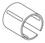
Figure 2.18 Latch tube sleeve
Latch tube sleeve part list
Part No. Qty. Description
| B80044 | 1 | Latch tube sleeve |
|---|
Tools
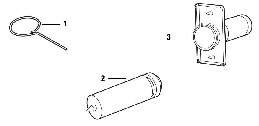
Figure 2.19 Installation tools
Installation tools part list
| Nomen | |||
|---|---|---|---|
| Item | clature | Part No. | Description |
| 1 | A25341 | Knob keeper tool | |
| 2 | KD325 | A01514 | Strike plate locating pin |
| 3 | KD315 | 1350393 | Faceplate marking chisel (1 1/8″ × 2 1/4″ ) |
| not shown | KD312 | 1487975 | Faceplate marking chisel (1″ × 2 1/4″ ) |
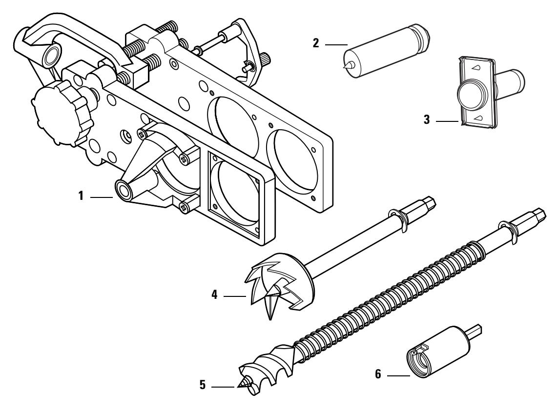
Figure 2.20 Boring jig kit
Boring jig kit parts list
| Item |
Nomen
clature |
Part no. | Description |
|---|---|---|---|
| Boring jig† | |||
| 1 | N/A | N/A | |
| 2 | KD325 | A01514 | Strike plate locating pin |
| 3 | KD315 | 1350393 | Faceplate marking chisel (1 1/8″ × 2 1/4″ ) |
| not shown | KD312 | 1487975 | Faceplate marking chisel (1″ × 2 1/4″ ) |
| 4 | KD309 | A54084 | 2 1/8″ diameter chassis hole bit assembly |
| 5 | KD318 | A54085 | 1″ diameter drill bit assembly |
| 6 | N/A | N/A | Adaptor for 3/8″ drill chuck† |
| 1–6 | KD304A | N/A | Boring jig kit |
† Can only be ordered as part of the KD304A boring jig kit.
3 SERVICE AND MAINTENANCE
This chapter contains instructions for replacing components, servicing and maintaining components, and troubleshooting common problems.
| See | |
|---|---|
| To | page |
| Replace knobs | 3–3 |
| Replace inside roses and rose liners | 3–7 |
| Replace outside rose and liner assemblies | 3–8 |
| Replace button assemblies | 3–4 |
| Lubricate cores | 3–10 |
| Align chassis and trim | 3–11 |
| Troubleshoot common problems | 3–12 |
REPLACING PARTS
Replacing the core and throw member
To remove the core and throw member:
- 1. Insert the control key into the core and rotate the key 15 degrees to the right.
- 2. Remove the core and throw member from the knob.
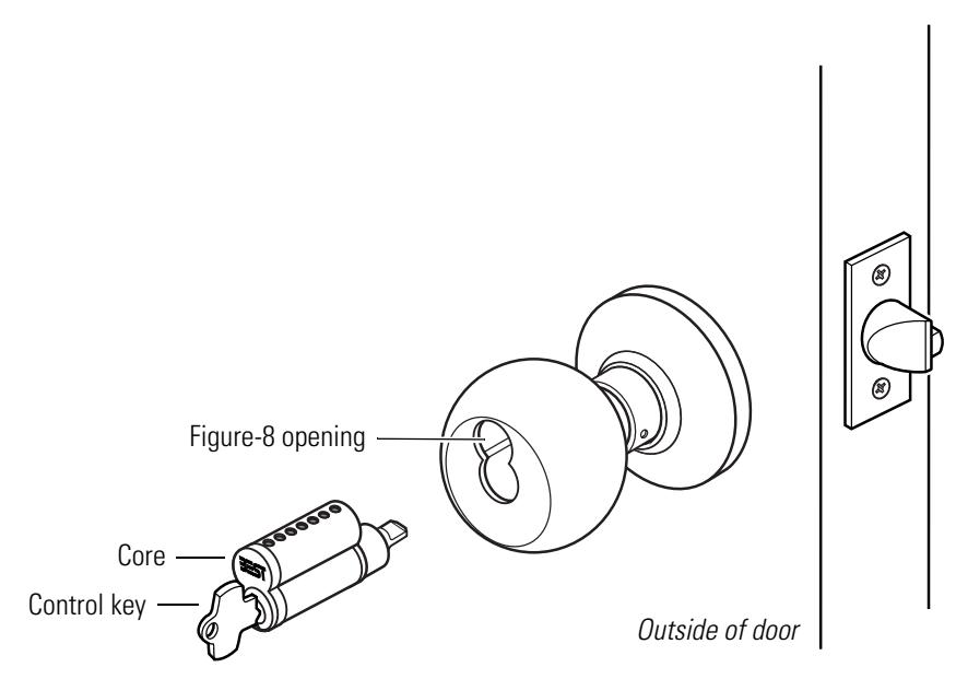
Figure 3.1 Removing and reinstalling the core
To reinstall the core and throw member:
1. For R function locks , insert a screwdriver into the figure-8 opening and turn the locking mechanism counterclockwise as far as it will go.
For all other function locks , go to step 2.
- 2. Insert the control key into the core and rotate the key 15 degrees to the right.
- 3. Using the control key, insert the core and throw member into the knob. Rotate the control key 15 degrees to the left and remove the key.
Replacing the knob To remove the knob:
- 1. For keyed knobs , remove the core and throw member ( page 3–2) . For all other knobs , go to step 2.
- 2. Insert the knob keeper tool into the hole on the trim ring, as shown in Figure 3.2 . Slide the knob off of the sleeve.
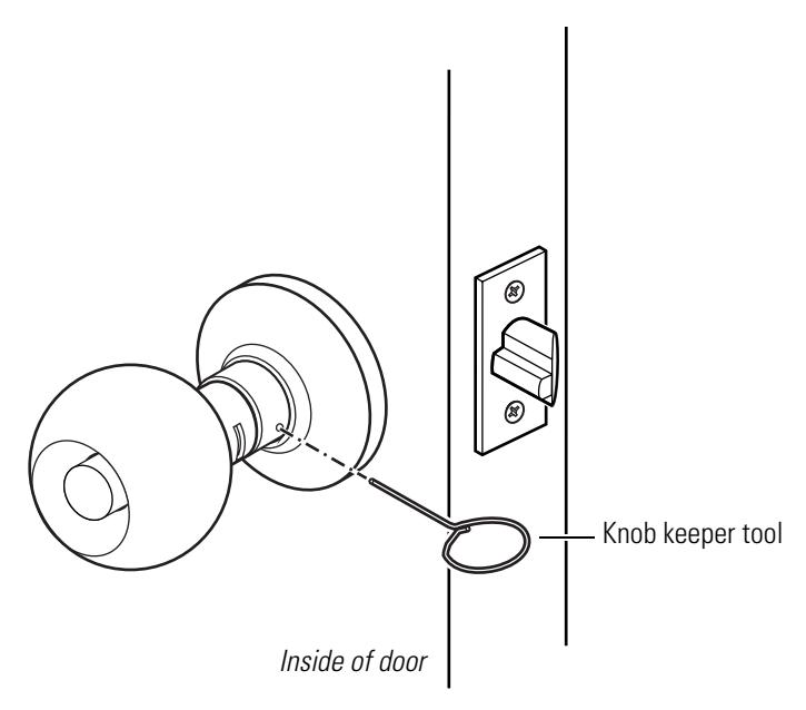
Figure 3.2 Removing the knob
To reinstall the non-keyed knob:
- 1. Align the two lugs (dimples) in the knob with the long slot in the sleeve, as shown in Figure 3.3.
- 2. Slide the knob onto the sleeve and firmly push on the knob until it is seated.
- 3. Turn the knobs to check that they operate smoothly.
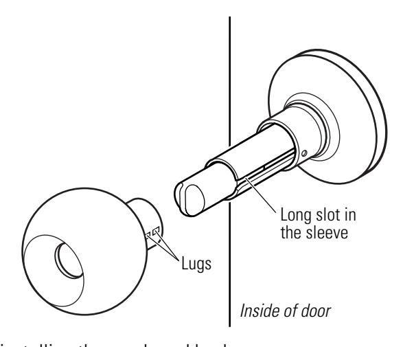
Figure 3.3 Reinstalling the non-keyed knob
To reinstall the keyed knob:
- 1. Align the two drive lugs on the inside of the knob with the short slots in the sleeve.
- 2. Insert the knob keeper tool into the hole on the trim ring and slide the knob onto the sleeve. Firmly push on the knob until it is seated.
- 3. Reinstall the core and throw member (page 3–2 ).
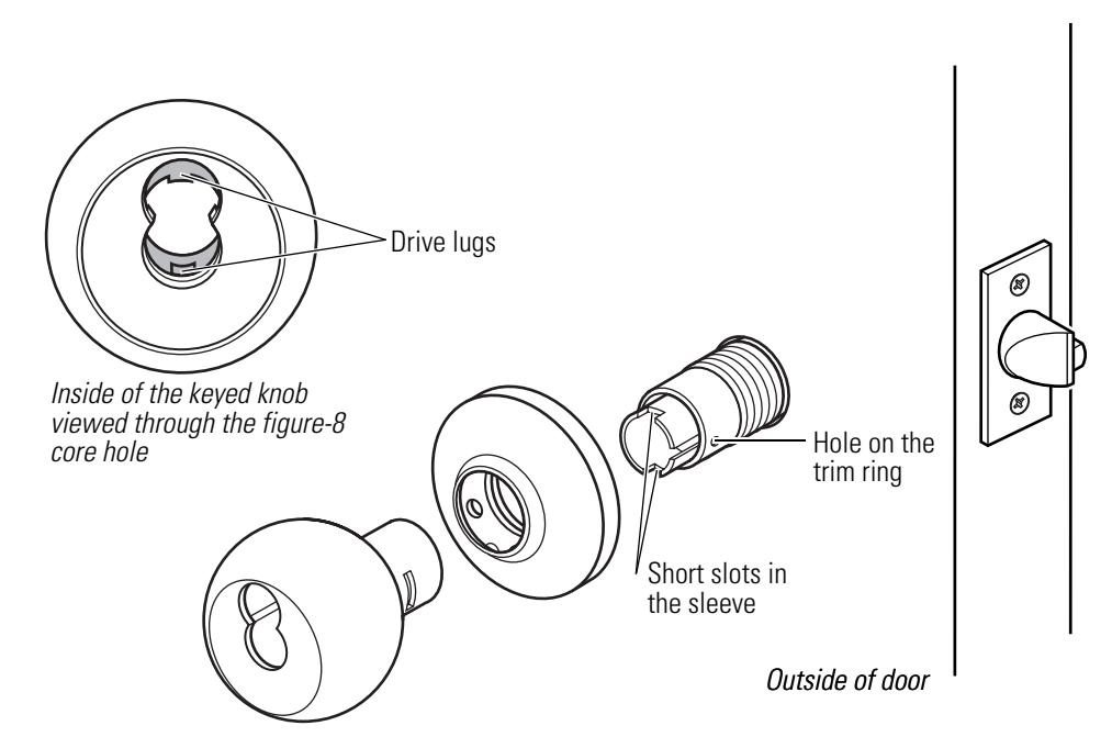
Figure 3.4 Reinstalling the keyed knob
Replacing the button assembly
To remove the button assembly:
Note: These instructions apply to all types of button assemblies.
- 1. Remove the knob ( page 3–3 ).
- 2. Insert a flat blade screwdriver behind the plastic button retainer and pry the button assembly from the locking bar.
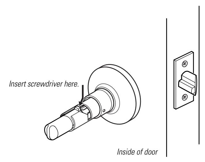
Figure 3.5 Removing the button assembly
To reinstall the outside button assembly:
- 1. Position the button assembly so that the button slot is horizontal.
- 2. Insert the button assembly into the cross slot on the inside of the sleeve. Firmly press the button assembly into place.
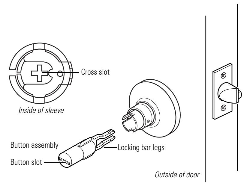
Figure 3.6 Reinstalling the outside button assembly
To reinstall the inside button assembly:
- 1. For turn buttons , align the button tab with the sleeve's top slot. For push buttons , go to step 2.
- 2. Firmly press the button assembly onto the locking bar until it is seated.
- 3. Reinstall the knob ( page 3–3) .
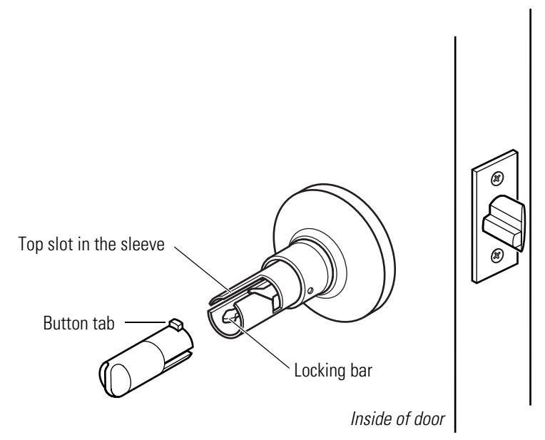
Figure 3.7 Reinstalling the inside button assembly
6K Series Service Manual 3–5
Replacing the bearing
To remove the bearing:
- 1. Remove the knob ( page 3–3 ).
- 2. Remove the bearing from underneath the trim ring. Slide the bearing off of the sleeve.
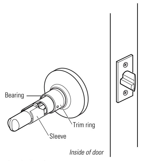
Figure 3.8 Removing the bearing
To reinstall the bearing:
- 1. Position the bearing so that the cutouts face the trim ring. Slide the bearing onto the sleeve and snap it into place underneath the trim ring.
- 2. Reinstall the knob ( page 3–3) .
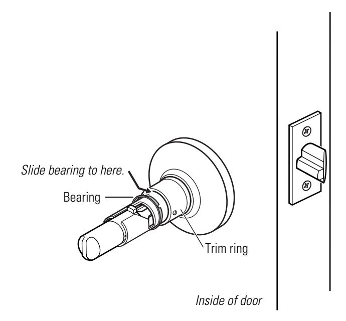
Figure 3.9 Reinstalling the bearing
Replacing the inside rose and rose liner
To remove the inside rose and rose liner:
- 1. Remove the inside knob (page 3–3 ).
- 2. Insert a flat blade screwdriver at the slot in the rose and pry the rose from the rose liner. Slide the rose off of the sleeve.
- 3. Unscrew the two through-bolts. Save the through-bolts.
- 4. Slide the rose liner off of the sleeve.
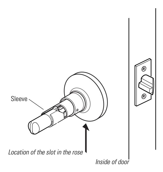
Figure 3.10 Removing the inside rose and rose liner
To reinstall the inside rose and rose liner:
- 1. Position the rose liner on the door so that the tab is at the bottom.
- 2. Install the two through-bolts through the rose liner and door in the top and bottom holes.
- 3. Tighten the rose liner onto the door with the through-bolts.
- 4. Align the slot in the rose with the tab on the rose liner and firmly press the rose until it is flush with the door.
5. Reinstall the knob ( page 3–3) .
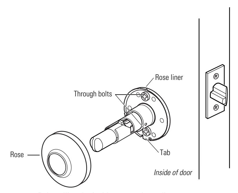
Figure 3.11 Reinstalling the inside rose and rose liner
Replacing the outside rose and liner assembly
To remove the outside rose and liner assembly:
- 1. Remove the outside knob (page 3–3 ).
- 2. Rotate the rose and liner assembly counterclockwise until it is free from the threading on the sleeve.
- 3. Remove the rose and liner assembly from the sleeve.
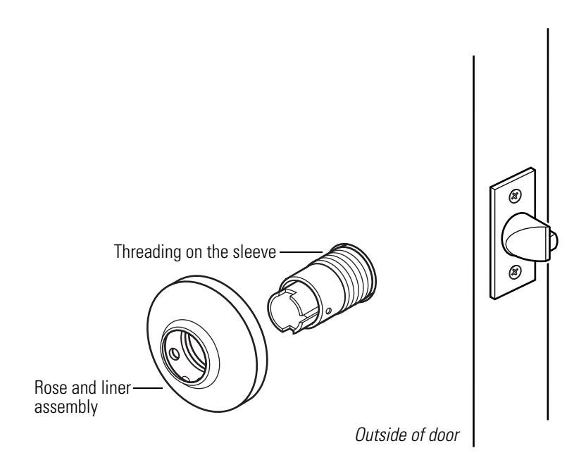
Figure 3.12 Removing the outside rose and liner assembly
To reinstall the outside rose and liner assembly:
1. Slide the rose and liner assembly onto the sleeve and rotate the rose and liner assembly clockwise until it is flush with the door.
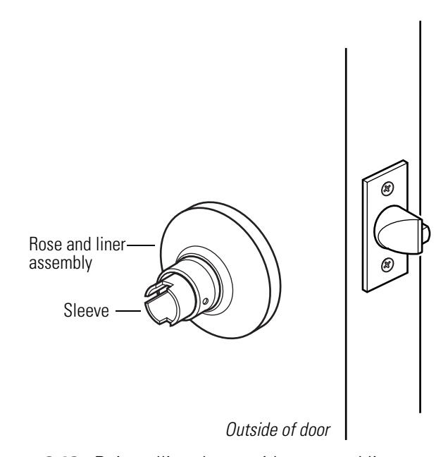
Figure 3.13 Reinstalling the outside rose and liner assembly
2. Reinstall the knob ( page 3–3) .
Replacing the lock chassis assembly
To remove the lock chassis assembly:
-
1. Remove the following components:
- knobs (page 3–3 )
- inside rose and rose liner (page 3–7)
- outside rose and liner assembly (page 3–8 ).
- 2. From the outside of the door, slide the lock chassis out of the door.
To reinstall the lock chassis assembly:
1. From the outside of the door, install the lock chassis. Make sure that the latch tabs engage the chassis frame and the latch tailpiece engages the retractor.
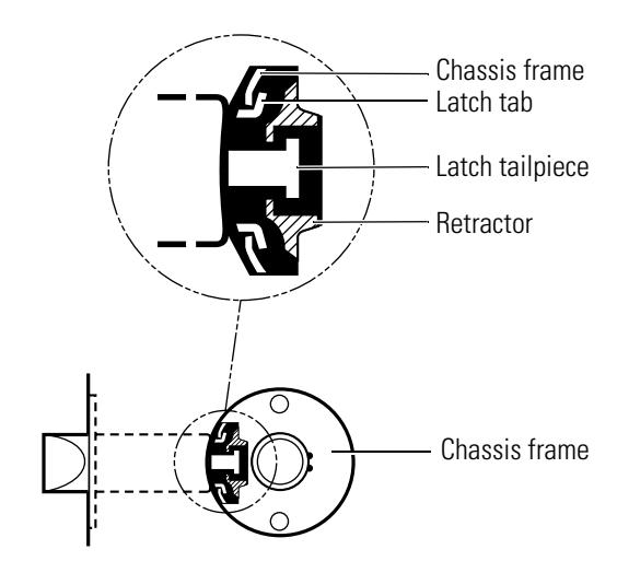
Figure 3.14 Engaging the retractor in the latch
-
2. Reinstall the following components:
- outside rose and liner assembly (page 3–9 )
- inside rose and liner assembly ( page 3–7 )
- knobs (page 3–3 ).
LUBRICATING THE CORE
Create a preventive maintenance plan that includes lubricating the core. To extend the life of the core, lubricate it regularly. Powdered graphite is the best choice for lubrication; LPS spray can also be used.

Do not lubricate a core with oil. Doing so will attract dirt.
For powdered graphite lubrication:
- 1. Remove the core from the lock ( page 3–2 ).
- 2. Dip a key in graphite. With the core inverted, insert the key into the keyhole and remove it; repeat several times, allowing the graphite to penetrate the barrels. OR
With the core inverted, spray graphite into the keyhole. Insert the key into the keyhole and remove it; repeat several times, allowing the graphite to penetrate the barrels.
For LPS lubrication:
- 1. Remove the core from the lock ( page 3–2 ).
- 2. Spray compressed air or LPS lubricant into the core to clean out all of the existing lubricant.
- 3. With the core inverted, spray the lubricant into the key opening, allowing the spray to penetrate the barrels.

Do not mix graphite with LPS lubricant.
ALIGNING THE CHASSIS AND TRIM
Establish a schedule to inspect locks, doors, and door hardware for proper alignment and operation. Occasionally a lock chassis and/or rose trim may become loose and require tightening.
To retighten a loose or misaligned chassis or rose trim:
-
1. Remove the following components:
- inside knob ( page 3–3 )
- inside rose and rose liner (page 3–7) .
- 2. Align the chassis with the latch. Make sure that the latch tabs engage the chassis frame and the latch tailpiece engages the retractor, as shown in Figure 3.15 .

Figure 3.15 Engaging the retractor in the latch
- 3. Tighten the through-bolts.
- 4. Test the knob operation to make sure that the latch tailpiece does not bind with the chassis retractor.
-
5. Reinstall the following components:
- inside rose and rose liner (page 3–7)
- inside knob ( page 3–3 ).
TROUBLESHOOTING
This table summarizes the possible causes for certain lock problems. The causes are listed in the order of likelihood. (The most likely cause is first, and so forth.)
| You notice… | Possible causes include… | You should… |
|---|---|---|
|
Knob won't return to its normal
position. |
a. There is binding between the
knob and rose. |
a. Ensure that the lock chassis is
centered within the door (page 3–11). |
| b. Knob bearing is damaged. |
b. Replace the knob bearing
(page 3–6). |
|
|
Key spins freely, but won't retract
the latch or unlock the door. |
a. Throw member is not installed. | a. Install the throw member. |
|
b. 6-pin core is installed with a 7-pin
throw member. |
b. Change the core or throw
member (page 3–2). |
|
|
Core doesn't fit into the knob core
hole. |
a. 7- pin core is installed with a
6-pin throw member. |
a. Change the core or throw
member (page 3–2). |
| b. Keyed knob is defective. |
b. Replace the keyed knob
(page 3–3). |
|
| Button doesn't pop out as expected. |
Button retainer or locking bar legs
are damaged. |
Replace the button assembly
(page 3–4). |
| Latch doesn't retract. | a. Latch tailpiece is broken. | a. Replace the latch assembly. |
|
b. Latch tailpiece didn't engage the
retractor correctly during installation. |
b. Reinstall the lock chassis
(page 3–10). |

A INSTALLATION INSTRUCTIONS
The following pages contain the Installation Instructions for 6K Cylindrical Locks .

Installation Instructions for 62K–65K Cylindrical Locks
For factory prepared doors only
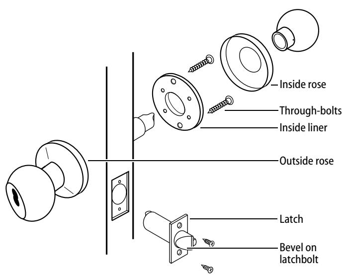
Figure 1 — Overview diagram
Caution: If you use hollow metal doors, determine whether the doors are reinforced enough to support the lock. If door reinforcement is not adequate, consult the door manufacturer for information on proper reinforcement.
Simplified instructions
- 1 Install the latch so that the bevel on the latchbolt faces the strike.
- 2 Adjust the outside rose assembly so that the chassis is centered in the door. Install the chassis from the outside of the door.
- 3 Install the inside liner, through-bolts, rose, lever, and strike.
For field door preparation and detailed installation instructions, see the following steps.
1 Position template
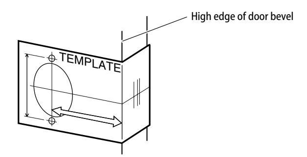
Figure 2 — Positioning the template
- 1 Fold the template and place in position on the high edge of the door bevel (see Figure 2) .
- 2 Mark the drill points for lock and latch.
Note: The suggested height from floor to centerline of the lock is 40 5/16 ″ . If steel frames are used, the latch centerline must be in line with the center of the strike preparation.
2 Bore two holes and install latch
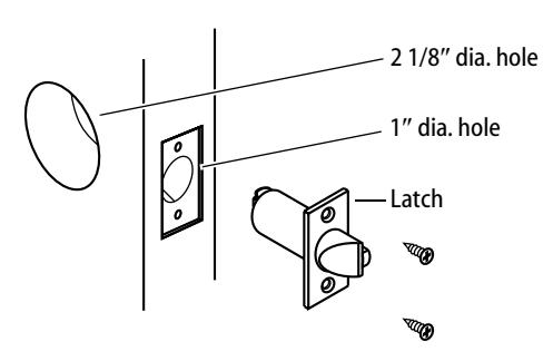
Figure 3 — Boring two holes and installing the latch
- 1 Bore a 2 1/8″ diameter hole from both sides of the door, to the center of the door as shown in Figure 3 .
- 2 Drill a 1″ diameter hole from the edge of the door that intersects the 2 1/8″ hole.
- 3 Mortise the door edge for the latch face.
- 4 Install the latch and check the door swing. Latch tabs should project into the 2 1/8″ diameter hole.
3 Remove inside knob and rose & liner assembly
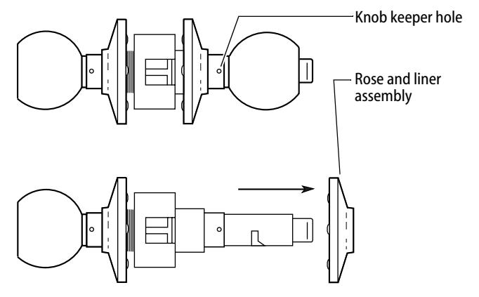
Figure 4 — Removing the inside knob and rose & liner assembly
- 1 Insert the spanner wrench tip into the knob keeper hole and depress the keeper.
- 2 Slide the knob off.
- 3 Remove the rose and liner assembly.
4 Adjust to door thickness
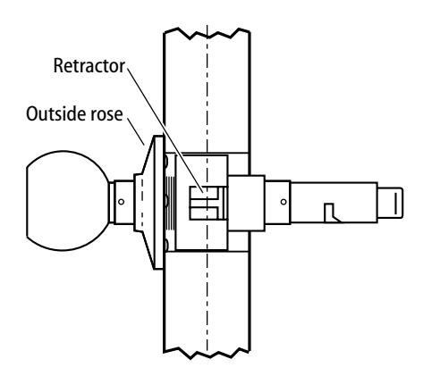
Figure 5 — Centering the retractor
- Rotate the outside rose in or out until the retractor is centered in the door.
- 5 Engage retractor in latch
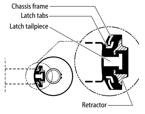
Figure 6 — Engaging the latch and retractor
- 1 With the latch in place, install the chassis from outside of the door.
- 2 Make sure that the latch tabs fit into the chassis frame and the latch tailpiece fits into the retractor.
6 Install liner and rose
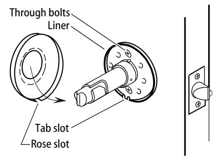
Figure 7 — Installing the rose over the liner
1 Separate the rose and liner (gently pry apart at the tab slot).
T56061/Rev A 1797989 ER-7991-19 May 2003
- 2 Place the liner in position with the tab slot at the bottom and tighten the through bolts.
- 3 Align the rose slot with the liner tab slot at the bottom and press the rose firmly onto the liner until flush with the door.
7 Install inside knob
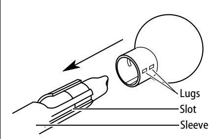
Figure 8 — Aligning and installing the inside knob
- 1 Align the two lugs ("dimples") on the knob shank with the long slot in the sleeve and slide the knob onto the sleeve.
- 2 Make sure that the knob keeper snaps into place.
- 3 Test both knobs for functionality.
8 Install strike plate
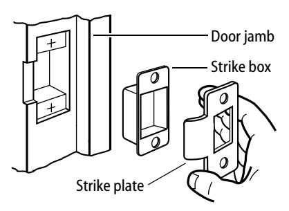
Figure 9 — Installing the strike box and plate
1 Mortise the door jamb to fit the strike box and strike plate. Make sure to align the strike plate and latchbolt centers.
Caution: The deadlocking plunger of the latchbolt must not enter the strike plate opening. The plunger deadlocks the latchbolt and prevents forcing the latch when the door is closed. A gap of more than 1/8" may reduce security and/or cause improper operation of the latchbolt.
2 Insert the strike box and secure the strike plate with the screws provided.
9 Check handing
Note: When BEST 6K locks are properly installed, the figure-8 hole must be in the
BEST ACCESS SYSTEMS
Indianapolis, Indiana
upper half of the knob. If it is not, change the hand of the lock.
To change the hand of the lock
1 Remove the core and throw member (if already installed). See Figure 11 .
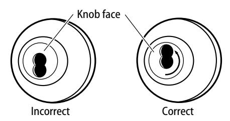
Figure 10 — Turning the knob face to correct the handing of the lock
2 Rotate the knob face one-half turn so that the figure-8 is in the upper half of the knob.
10 Install core
For 'R' function locks only
■ Simulating the throw member, insert a screwdriver into the figure-8 opening and turn the locking mechanism counterclockwise as far as it will go before installing the core.
For all functions (including 'R' function)
For 6-pin core users only : Slide the spacer — supplied with your 6-pin cores — over the 7-pin throw member.
Note: If you have ordered 6-pin cores, you will get one spacer per core with your order. Spacers are not supplied with locks.
- 1 Insert the throw member (or throw member and spacer) into the back of the core.
- 2 Insert the control key into the core and turn the key 15 degrees clockwise.
- 3 Insert the core and throw member into the knob with the control key as shown in Figure 11 .
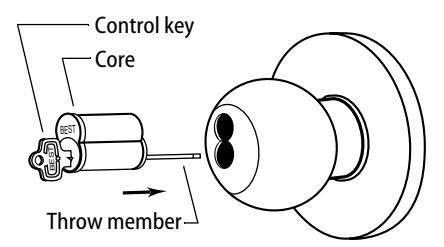
Figure 11 — Installing the core
4 Turn the key 15 degrees counterclockwise and remove the key.
B INDEX
| A | D |
|---|---|
| AB chassis and trim | D chassis and trim |
| function conversion for 2–16 | function description for 2–2 |
| function description for 2–2 | part numbers and drawings for 2–8 |
| part numbers and drawings for 2–6 | D chassis assembly 2–8 |
| AB chassis assembly 2–6 to 2–7, 2–9 to | diagrams, exploded |
| 2–11, 2–13 | see part numbers and drawings |
| aligning the chassis and trim 3–11 | documentation package 1–1 |
| drawings of parts | |
| B | see part numbers and drawings |
| B chassis and trim | |
| function description for 2–5 | E |
| part numbers and drawings for 2–7 | E chassis and trim |
| bearing 2–6 to 2–15 | function conversion for 2–16 |
| reinstalling 3–6 | function description for 2–3 |
| removing 3–6 | part numbers and drawings for 2–9 |
| boring jig kit 2–22 to 2–23 | exploded diagrams |
| button assembly | see part numbers and drawings |
| push button assembly 2–7, 2–10, 2–13 | |
| reinstalling the inside assembly 3–5 | F |
| reinstalling the outside assembly 3–5 | faceplate marking chisel 2–22 to 2–23 |
| removing 3–4 | function conversion 2–16 |
| slotted button assembly 2–9 to 2–10 | function description |
| turn button assembly 2–6, 2–11 | for AB chassis and trim 2–2 |
| for B chassis and trim 2–5 | |
| C | for D chassis and trim 2–2 |
| certifications and standards 1–1 | for E chassis and trim 2–3 |
| chassis screws 2–6 to 2–8, 2–10 to 2–15 | for L chassis and trim 2–4 |
| cores | for LL chassis and trim 2–5 |
| lubricating 3–10 | for N chassis and trim 2–4 |
| reinstalling 3–2 | for P chassis and trim 2–4 |
| removing from a knob 3–2 | for R chassis and trim 2–3 |
| for Y chassis and trim 2–4 | |
| K | P | non-keyed knob 3–3 | |
|---|---|---|---|
|
knob keeper tool 2–22
knobs 2–19 |
P chassis and trim
function description for 2–4 part numbers and drawings for |
outside button assembly 3–5
outside rose and liner assembly 3–9 |
|
|
L
L chassis and trim function conversion for 2–16 function description for 2–4 part numbers and drawings for 2–10 latch tube sleeve 2–22 latches 2–21 LL chassis and trim |
2–13
part numbers and drawings for AB chassis and trim 2–6 for assembly tools 2–22 for B chassis and trim 2–7 for D chassis and trim 2–8 for E chassis and trim 2–9 for knobs 2–19 for L chassis and trim 2–10 |
removing
bearing 3–6 button assembly 3–4 core 3–2 inside rose and rose liner 3–7 knob 3–3 lock chassis assembly 3–9 outside rose and liner assembly 3–8 |
|
|
function conversion for 2–16
function description for 2–5 part numbers and drawings for 2–11 |
for latches 2–21
for LL chassis and trim 2–11 for N chassis and trim 2–12 for P chassis and trim 2–13 |
S
single dummy trim function description for 2–4 |
|
|
lock chassis
aligning 3–11 reinstalling in the door 3–10 removing from the door 3–9 lubricating cores 3–10 |
for R chassis and trim 2–14
for roses, rose liners, and rose spacers 2–18 for single dummy trim 2–20 for strikes and strike boxes 2–17 |
part numbers and drawings for
2–20 strike plate locating pin 2–22 to 2–23 strikes and strike boxes 2–17 support, technical 1–2 |
|
| N |
for throw member 2–19
for Y chassis and trim 2–15 |
T | |
|
N chassis and trim
function description for 2–4 part numbers and drawings for 2–12 N chassis assembly 2–12 numbers for parts see part numbers and drawings |
R
R chassis and trim function description for 2–3 part numbers and drawings for 2–14 R chassis assembly 2–14 reinstalling bearing 3–6 core 3–2 inside button assembly 3–5 inside rose and rose liner 3–7 keyed knob 3–4 lock chassis assembly 3–10 |
technical documentation package
1–1 technical support 1–2 throw member 2–19 troubleshooting problems 3–12 Y Y chassis and trim function description for 2–4 part numbers and drawings for 2–15 Y chassis assembly 2–15 Y function rose assembly 2–15 |
|