BEST L Series Cabinet Locks Catalog
Open the original PDF document
View PDF

L Series
Cabinet Locks
TABLE OF CONTENTS
|
L Series
3L Features/specifications2 3L How to Order2 5L Latchbolt specifications/mounting positions3 5L Deadbolt mounting positions/strikes4 5L How to Order4 8L Features/specifications5 E Series 1E Features/specs/ How to Order5 |
P Series
2P Features/specifications7 S Series 2S Functions/specs/ How to Order8 3S Features/specs/ How to Order9 Service Equipment10 Patented Keying System11 |
|
|---|---|---|
| 5E Features/specs/ How to Order6 |
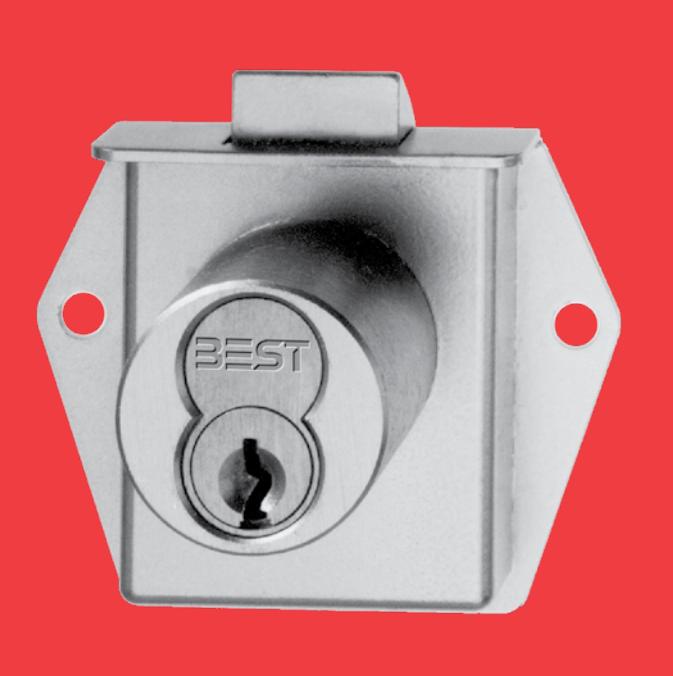
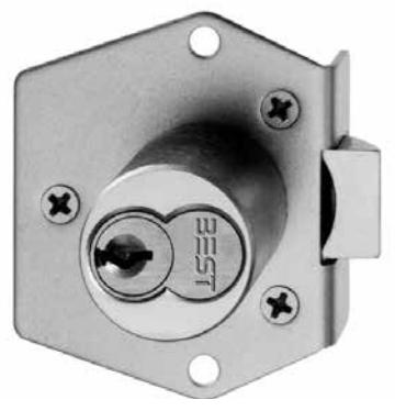
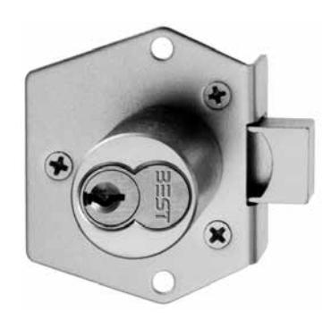
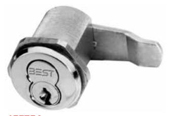
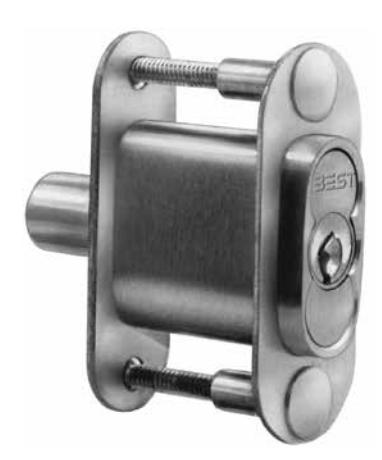
3L Series Deadbolt
Operation–Deadbolt locked and unlocked by key. Must be locked by key after door is closed. Key may be withdrawn in locked position and unlocked position.
Specifications
Material – Bolt is stainless steel, springs are phosphor bronze, all other parts are brass.
Backset – 7/8"
Bolt – 1 1/8" x 3/16" – 3/4" throw
Case – Height 1 21/32", width 2 1/8", thickness 21/32", hole spacing 1 39/64" x 1 1/4"
Cylinder diameter – 1 1/8"
Cylinder length – 7-pin tumbler, 1 13/64"
Finish – Base finish 606 unless otherwise specified.
Keeper plate – None supplied.
Products protected by one or more of the following patents:
U.S.
4531390 4663839 4055973 4722204 5794472 4531389 4075878
4768360 4843852 4633690 4616394 D290085 5590555
Canada 1229234
3L7RD2 (Vertical Only)
How To Order – 3L
| 3L | 7 | R | D | 2 | 606 | Std. |
|---|---|---|---|---|---|---|
| Series | Core |
Mounting
Housing |
Latch Type | Hand Type |
Standard
Finish |
Cylinder
Length |
|
3L– coin
box lock |
7– 7 pin
housing accepts all BEST cores |
R– rim | D– deadbolt | 2– vertical |
606 612
626 (cylinder only) |
Standard
1 1/2" 2" |

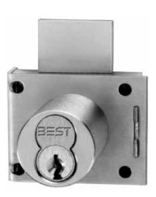
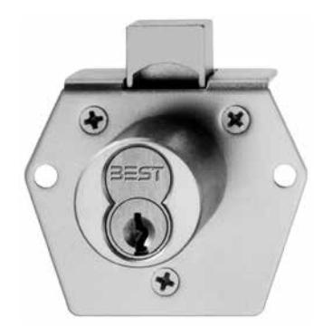
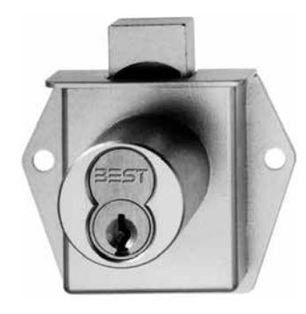
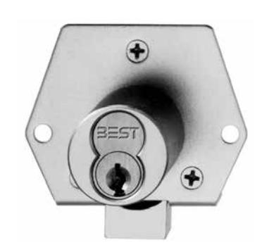
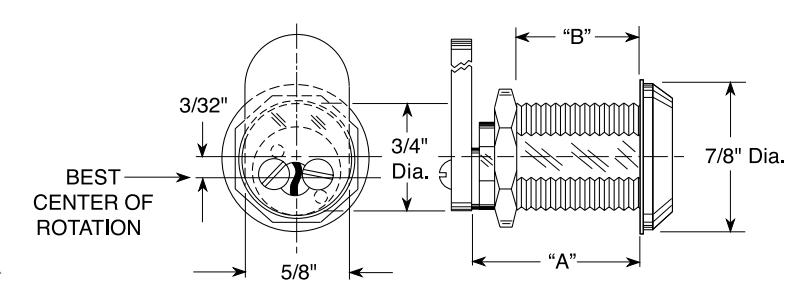
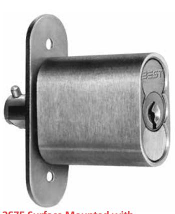
5L Series Latchbolt
Specifications
Latchbolt function – Retracted by key to unlock. Key may be withdrawn only in locked position
Deadbolt function – Locked and unlocked by key. Must be locked by key after door is closed. Key may be withdrawn in locked position and unlocked position
Backset – 7⁄8"
Body thickness – 1⁄2"
Case – Length 2 1⁄8", width 2 19⁄32", thickness 21⁄32", hole spacing 2 3⁄16"
Cylinder diameter – 1 1⁄8"
Cylinder length – 1 1⁄16"
Deadbolt – 3⁄4" x 25⁄64" – 1⁄2" throw
Door thickness – 5⁄8" minimum for rim type, 21⁄32" minimum for mortise type.
Face – 1 7⁄8" x 21⁄32"
Latchbolt – 3⁄4" x 25⁄64" – 9⁄32" throw
Material – Nickel plated zinc case and bolts, stainless steel cover, phosphor bronze spring.
Strike plate – 3⁄64" x 11⁄16" x 1 7⁄8", hole spacing 1 7⁄16", 1 1⁄4" wide lip.
T-Option – Key is removeable only in locked position. (Deadbolt Only)
5L Series – Latchbolt Mounting Positions
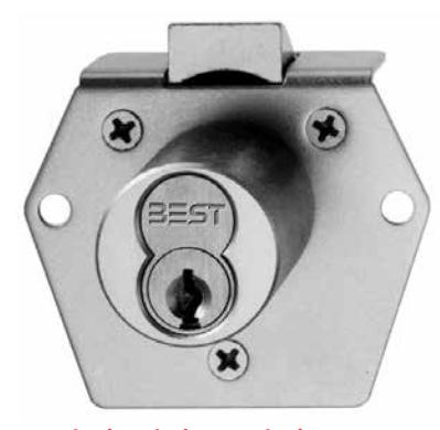
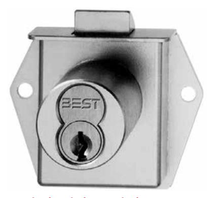
Rim (Vertical Mounting) Mortise (Vertical Mounting)
Left-hand (Vertical Mounting) Inverted
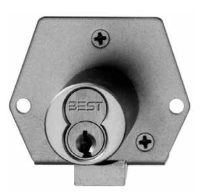
5L Series – Deadbolt Mounting Positions
Rim (Vertical Mounting) Mortise (Vertical Mounting)
Left-hand (Vertical Mounting) Inverted
5L Series – Strikes
Strike plate specification – 3⁄64" x 11⁄16" x 1 7⁄8"; hole spacing 1 7⁄16"
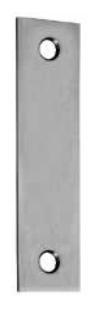
A-450 A00450
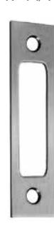
A-451 A00451
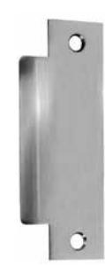
A-452 A00452
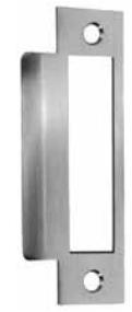
A-453 A00453
Standard strike supplied unless otherwise specified
How To Order – 5L
| 5L | 7 | R | D | 2 | 606 | |
|---|---|---|---|---|---|---|
| Series | Core |
Mounting
Housing |
Latch
Type |
Hand |
Standard
Finish |
Options |
| 5L |
7– 7 pin
housing accepts all BEST cores |
M– mortise
R– rim |
D– deadbolt
L– latchbolt |
2– vertical
5– inverted |
606 612
626 (cylinder only) |
T– deadlock
(deadbolt only) TR– special trim ring |

8L Series – Mail Box Locks
The 8L7SPR mailbox lock features the convenience of the interchangeable core, allowing quick combination change, and is adaptable to a number of different mailbox manufacturers. The 8L7SPR can be masterkeyed into any existing BEST® system. Variations are available for adaptation purposes.
To order: Specify mail box manufacturer and style number, and/or send sample of mail box door. Specifications
Housing – Steel, zinc plated.
Cylinder – Machined from solid aluminum.
Cylinder head diameter – 1 1/8".
Latchbolt – 9/32" square with bevel.
Handing – Right-hand standard – 8LSPR.
Finish – 627 standard.
Call product support for manufacturer model assistance 800-392-5209.
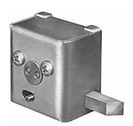
8L7SPR (Inside)
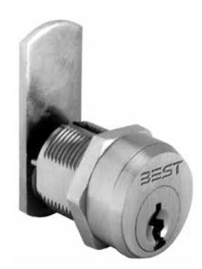
1E Series – Slabbed Cabinet Mortise Cylinders
The special cylinders are threaded to the head, mounted with a hex nut, and slabbed on both sides to prevent turning in the mounting hole.
Specifications
Length – 1ED7D4: 1 15/32" from head to cam. 1EE7E4 1 1/4" from head to cam.
Cylinder diameter – 1 5/32", 7/8" across flats.
Thread – 1.150 - 32 (NS - 2A).
Finish – 626 standard.
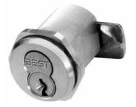
1ED7D4 Direct motion cam prevents key from being withdrawn in unlocked position. Reversible cam may be assembled for required hand at installation.
1EE7E4 270° lost motion cam permits key to be withdrawn when locked or unlocked.
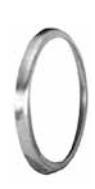
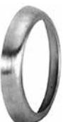
RP Standard Ring Package The RP standard ring package includes a 1E-R3 ( 3⁄16" ) and 1E-R5 ( 3⁄8" ) ring.
1E-R3– 3⁄16" 1E-R5 – 3⁄8"
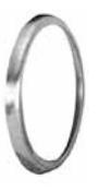
RP1 Ring Package
The RP1 ring package for the 1E-76 cylinder includes a1E-R2 ( 1⁄8" ) and 1E-R3 ( 3⁄16") ring.
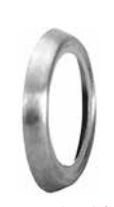
1E-R2 – 1⁄4" 1E-R3 – 3⁄16"
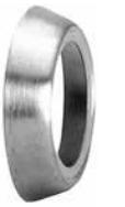
RP2 Ring Package
The RP2 ring package for the 1E-64 cylinder includes a 1E-R2 ( 1⁄8" ) and 1E-R4 ( 1⁄4") ring.
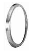
1E-R2 – 1⁄4" 1E-R4 – 1⁄4"
RP3 Ring Package
The RP3 ring package for the 1E-62, 1E-72 and 1E-74 cylinders includes a 1E-R2 ( 1⁄8" ) and a 1E-R5 ( 3⁄8" )
1E-R2 – 1⁄8"
1E-R5 – 3⁄8"
Note: RP5 includes – 1ER2, 1ER4 & 1ER5
How To Order – 1E 1E 7 E4 RP3 626 Cylinder Diameter Core Housing Function Code Rings Finishes 1ED– 1 5⁄32" 1EE– 1 5⁄32" 7– 7 pin housing accepts all BEST cores D4– direct motion E4– lost motion RP– 3⁄16" and 3⁄8" RP1– 1⁄8" and 3⁄16" RP2– 1⁄8" and 1⁄4" RP3– 1⁄8", 1⁄4" and 3⁄8" 605 606 612 613 625 626
5E Series 3/4" Utility Cylinder
Specifications
5E6 – Series
"A" (Body length) – 31/32"
Body diameter– 3/4"
Body – 6 pin
Head diameter– 7/8"
Finish – 626
"B" (Max. mounting thickness )– 11/16"
5E7 - Series
"A" (Body length) – 1 1/8"
Body diameter – 3/4"
Body – 7 pin
Head diameter – 7/8"
Finish – 626
"B" (Max. mounting thickness) – 27/32"
5E– Straight Cam
Standard 5E Assembly unit includes:
Keyed 3⁄4" with cam (specify cam length - if length is not specified, the 5EC1 x 7⁄8" will be supplied as standard), hex nut, spacer collar (not supplied unless length is specified), and lock washer.
Application:
Fits standard 3⁄4" cylinder installations for e.g. desks, file cabinets, coin-operated vending machines, utility cabinets, storage cabinets, elevators, and security alarm control panels.
Material finish:
Solid extruded brass cylinder body, 626 finish standard.
Cam motion operation:
TYPE "A" - Standard 5E cylinder key rotates 360° right or left.
TYPE "B" - Limited motion cam operation 90° or 180° as required.
TYPE "C" - Lost motion cam operation 90°: Key removal with cam in locked or unlocked position.
TYPE "D" - Throw member-type drive. Two throw pins engage key plug from rear of cylinder. (Direct 360° action-R or L.) Throw member types available upon request.
Cam & Spacer Collar:
Cam variations are detailed in the cylinder catalog section and may be modified for use on the 5E cylinder. Standard cams are factory attached to key plug with screws. Spacer collars may be required to position the cam for proper lock operation. The spacer collar is installed between the 5E cylinder head and the mounting surface. Both straight collars and special tapered collars available by request.
To order: For more information see E series catalog section.
How To Order – 5E
| 5E | 7 | A | 1 | 2C | 606 | 4B | 21 | 12 | R | 90 | 626 |
|---|---|---|---|---|---|---|---|---|---|---|---|
|
Series
Body |
Lock |
Keyway
Code |
Combination
Code |
Cam
Motion |
Ring
Length |
Cam |
Cam
Length |
Mounting
Position |
Cam
Direction |
Degree of
Rotation |
Finish |
| 5E–3⁄4" |
6– 6
pin 7– 7 pin cores |
designate
specific keyway (A, E, etc.) |
1– uncomb
inated 2– combinated |
A– direct
B– limited C– lost D– throw member |
R701–
1⁄16" R702– 1⁄8" R703– 3⁄16" R704– 1⁄4" R705– 5⁄16" R706– 3⁄8" R707– 7⁄16" R708– 1⁄2" |
1–fixed
straight 2A– fixed offset in 2B–fixed offset out 3–lost motion 4A–lost motion offset in 4B–lost motion 4B–lost motion offset out D–direct throw |
10– 5⁄8"
12– 3⁄4" 14– 7⁄8" 16– 1" and so forth in 1⁄16 of inch |
3– 3 o'clock
6– 6 o'clock 9– 9 o'clock 12– 12 o'clock |
R– right
L– left |
90– 90º
180– 180º 360– 360º |
626–
standard |

2P Series Push Locks for File Cabinets
Specifications
Material – All parts are solid brass; phosphor bronze springs.
Dimensions – See illustrations and table below.
Finish – 2P Series 626 (satin chrome) standard finish.
2P series finish to match satin chrome. (7 pin only).
The 2P series incorporates the BEST® interchangeable core and requires special cabinet preparation. It may be keyed individually, keyed alike, masterkeyed or grand-masterkeyed with other BEST® lock of any type.
To order: Specify proper lock, finish and keying instructions.
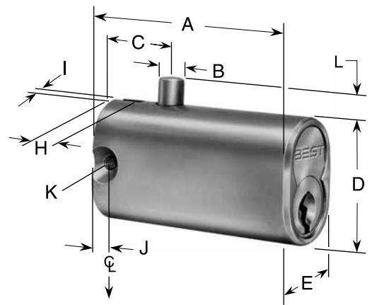
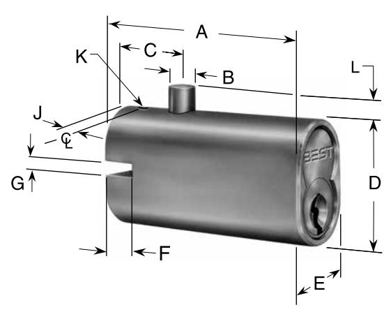
2P73 Vertical mounting slot 2P74 Horizontal mounting slot
2P Series Specifications
|
Dimensions in inches
Vertical Mounting Slot |
||||||||||||
|---|---|---|---|---|---|---|---|---|---|---|---|---|
| A | B | C | D | E | F | G | H | I | J | K | L | |
|
2P73
(7Barrel) |
2 9⁄32" | 1⁄4" | 1 9⁄32" | 1 1⁄8" | 3⁄4" | 5⁄16" | 1⁄8" | 5⁄32" | #6-32 | 5⁄32" | ||
| Horizontal Mounting Slot | ||||||||||||
|
2P74
(7Barrel) |
2 9⁄32" | 1⁄4" | 19⁄32" | 1 1⁄8" | 3⁄4" | 5⁄16" | 1⁄8" | 5⁄32" | #6-32 | 5⁄32" |
2S Series Push Locks For Sliding Doors
Specifications
Case – extruded brass.
Width – 1 1/2"
Thickness – 23/32"
Inside face plate – 2 3/4" x 7/8", hole spacing 2 3/16".
Detachable face plate – 1/16" x 1 1/8" x 2 3/4", hole spacing 2 3/16".
Strike – 2 3/4" x 1 1/8", 2 3/16" hole spacing.
Finish – 626 supplied unless otherwise specified.
2S73 Surface Mounted (BHMA E07161)
Function Code Chart
|
Function
Code |
Door |
Bolt
Thickness |
Operation |
|---|---|---|---|
| 3 | 7/8" to 1 5/8" |
19/32" dia.
1/ 2" throw |
When unlocked, case of lock
moves out through door stile and may be used as handle for moving door. To lock 2S73 and 2S74, push |
| 3 x TBM | 7/8" to 1 5/8" |
19/32" dia.
1/2" throw |
case in through door. Spring
locking action. To lock 2S75, operate key and push case "IN" through door |
| 4 x TBM | 7/8" to 1 5/8" |
19/32" dia.
3/4" throw |
to engage bolt retaining
pin behind strike plate in opposite door. |
| 5 x TBM | 3/4" to 1 5/8" |
1/2" dia. x 7/16" bolt
engagement. 1/8" locking pin |
2S74 x TBM Through-Bolt Mounted (BHMA E07161)
How To Order 2S
| 2S | 7 | 5 | 626 |
|---|---|---|---|
| Series |
Core
Housing |
Function
Code |
Standard
Finish |
|
2S– push lock for
sliding door accepts all BEST cores |
7– 7 pin housing | see above | 626 |
Must specify key mark and number of keys or designate L/C for less core.
2S75 Surface Mounted with retaining pin (BHMA E07181)

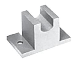
3S Series Sliding Panel Locks
Specifications
Strike strap – stainless steel, 1/2" wide.
Locking housing – aluminum.
Finish – 627 aluminum only.
Operation – A stainless steel strap mounts permanently on the inner sliding panel. When panels are closed, the tongue of the strike strap extends beyond the edge of the outer panel. To lock panels, slide lock housing onto overlapping tongue and up against edge of outer panel. Lock by turn of key. Key is removable in locked position only.
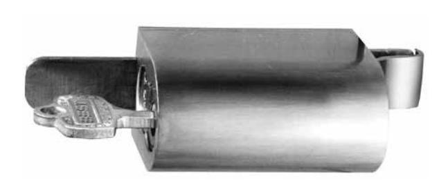
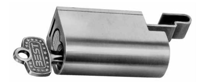
3S75 3S77
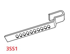
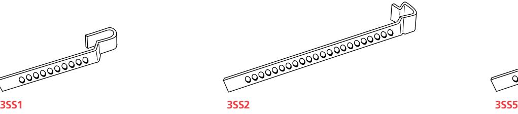
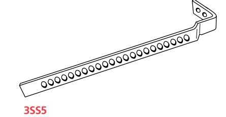
Specifications
| Strike strap | Length | Thickness |
|---|---|---|
| 3SS1 | 4 1/4" | 1/4" |
| 3SS2 | 6 1/4" | 7/32" |
| 3SS3 | 6 1/4" | 5/16" |
| 3SS4 | 6 1/4" | 13/32" |
| 3SS5 | 6 1/4" | 3/4" |
How To Order – 3S
| 3S | 7 | 5 | S2 | 627 |
|---|---|---|---|---|
| Series | Core | Mounting Housing | Latch Type | Hand |
|
3S– sliding panel
lock |
7– 7 pin
housing accepts all BEST cores |
5– straight lock housing
7– captured panel lock 8– housing with 1" extension |
S1– 4 1/4" x 1/4"
S2– standard unless otherwise specified S3– 6 1/4" x 5/16" S4– 6 1/4" x 13/32" S5– 6 1/4" x 3/4" |
627– standard |
Service Equipment
5ED253 Thread Tap
Matches standard 24 thread on 5E series cylinder locks.
To order specify: 5ED253 thread tap
5ED261 Capping Block
The capping process for single shearline 5E cylinders requires the following:
5E slide caps:
- 5ECP6– 6 pin
- 5ECP7– 7 pin
5E Cylinder:
- 5ED261 Capping Block
- 5ED262 Cap Depressor
Service Equipment for 5E Cylinders (single shearline)
BEST single shearline locks may be combinated to Grand Master, Master and/or any operating combinations in your BEST system. Utilizes the AD433 Key Combinator.
See (D Series) Service Equipment Catalog for details.
5ED250 Combinating Kit (single shearline)
Similar to standard CD431 kit for figure 8 cores, the single shearline kit provides a special 5ED261 capping block, springs (5ES1) and caps (5ECP)
To order specify:
- 5ED250 2 (for A2 system)
- 5ED250 3 (for A3 system)
- 5ED250 4 (for A4 system)
Pin Segments (included in kit)
Close tolerance segments assist in accurate combinating.
To order : Contact your local BEST Representative.
Core Springs (included in kit)
This properly sized spring facilitates consistent action in all BEST figure 8 cores.
To order specify: 22S springs. Core Caps (included in kit)
Barrels are securely sealed by applied core caps.
To order specify: 21C caps.
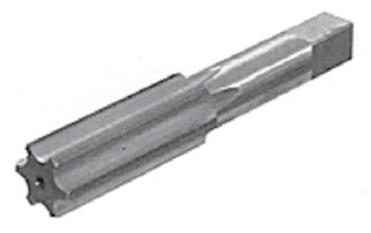
5ED253– Thread Tap
5ED261– 5E Capping Block

5ED250– Combinating Kit (single shearline)

CORMAX ™ Patented Keying System
BEST® CORMAX™ is the premier patented keying system offered by BEST. CORMAX will meet your needs for security, key control, and convenience. A simple solution with no compromising allowed.
CORMAX is the upgrade path for existing BEST Standard, Premium, and MX8 customers; and it is an essential element of non-residential access control as security administrators strive to eliminate the unauthorized duplication of keys.
CORMAX™ Patented Keying System
CORMAX offers the following features and benefits:
- A long-term US utility patent that guarantees the extended useful life of the system through 2027.
- A second, independent locking mechanism that utilizes a patented set of built-in side pins to provide higher security.
- Several levels of geographical exclusivity, including national exclusivity, are available via the patented side pin feature.
- CORMAX cores and keys are available exclusively through BEST sales offices. Key blanks are only sold to individuals authorized by the customer to ensure key blanks do not end up in the possession of unauthorized personnel either inside or outside the customer's facility.
- CORMAX cores are certified to meet the security, safety, and reliability requirements of BHMA A156.5 Grade 1.
- Picking and drilling resistance options are available if higher levels of security are desired.
- Complete factory masterkeying service offered, and at no charge with purchase of BEST locksets and exit devices.
- Keyways are organized in families of four keyways each, with double-milled and quad-milled key levels to facilitate the design of masterkey systems in multi-building campuses.
- BEST CORMAX cores are compatible with all existing BEST interchangeable core housings, eliminating the need for new or modified locksets.

6161 East 75th Street Indianapolis, IN 46250 USA
Phone 855-365-2407
bestaccess.com