BEST E Series Mortise and Rim Cylinders Service Manual
Open the original PDF document
View PDF
SERIES
SERVICE MANUAL

CREDITS/COPYRIGHT
©2001–2002 Best Lock Corporation dba Best Access Systems. All rights reserved. Printed in the United States of America.
Information in this document is subject to change without notice and does not represent a commitment on the part of Best Access Systems.
This publication is intended to be an accurate description and set of instructions pertaining to its subject matter. However, as with any publication of this complexity, errors or omissions are possible. Please call your BEST distributor or Best Access Systems at (317) 849-2250 if you see any errors or have any questions. No part of this manual and/or databases may be reproduced or transmitted in any form or by any means, electronic or mechanical, including photocopying, recording, or information storage and retrieval systems, for any purpose, without the express written permission of Best Access Systems.
This document is distributed as is, without warranty of any kind, either express or implied, respecting the contents of this book, including but not limited to implied warranties for the publication's quality, performance, merchantability, or fitness for any particular purpose. Neither Best Access Systems, nor its dealers or distributors shall be liable to the user or any other person or entity with respect to any liability, loss, or damage caused or alleged to be caused directly or indirectly by this publication.
The Life Safety Code is a registered trademark of the National Fire Protection Association.
Written and designed by Best Access Systems and Avalon Group, Inc., Indianapolis, Indiana.
T61839 Rev – 1879076 ER7991-6 June 2002
CONTENTS
FIGURES VII
GETTING STARTED 1–1
Introduction 1–1
Certifications and standards 1–2 Documentation package 1–3
Support services 1–3
Telephone and web technical support 1–3
PARTS FOR 1E SERIES 2–1
Exploded diagrams and parts lists 2–2
Mortise cylinder 2–2
Rim cylinder 2–3
Thumbturn cylinder 2–4
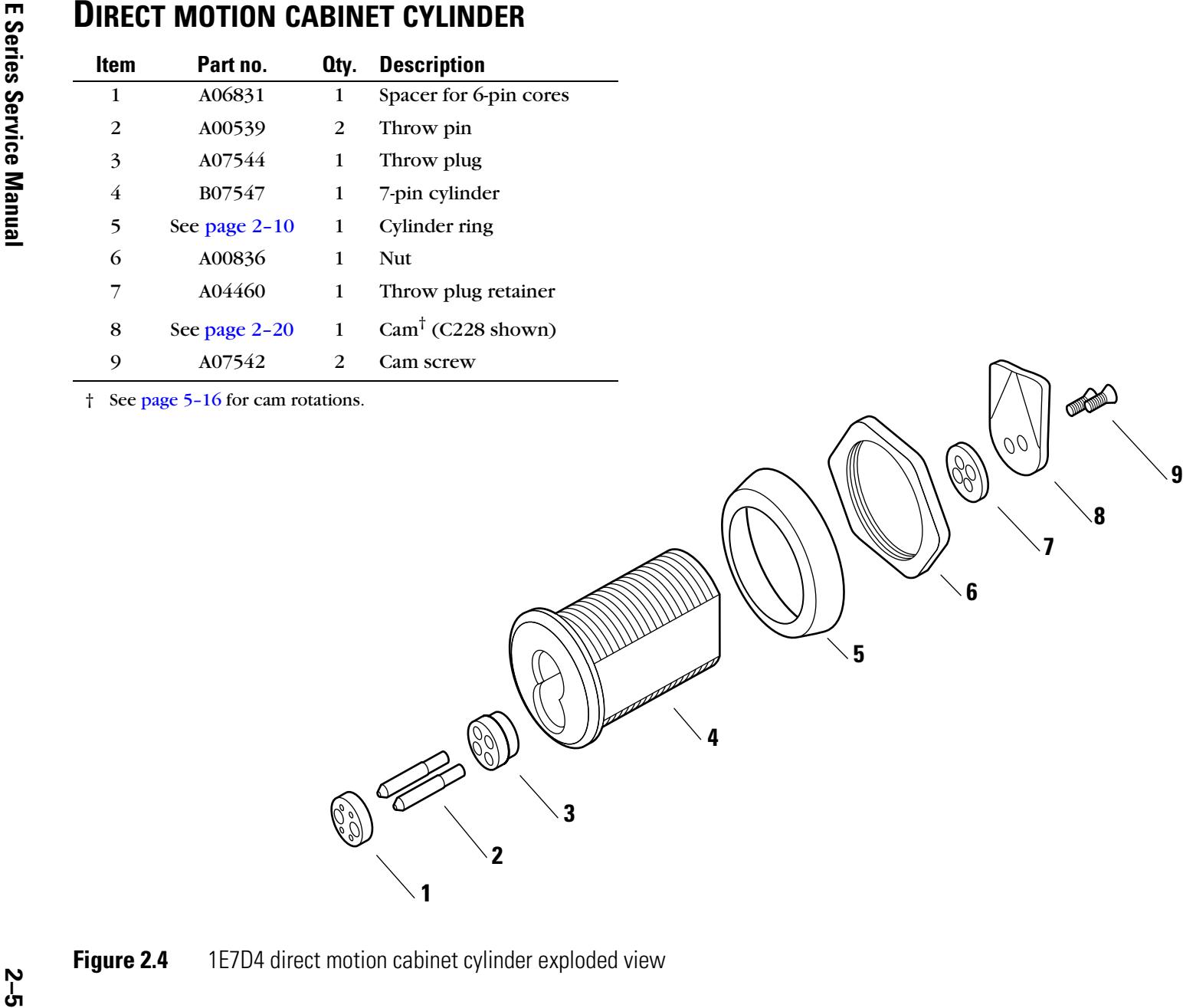
Direct motion cabinet cylinder 2–5
Lost motion cabinet cylinder 2–6
Special mortise cylinder applications 2–7
Dust cover cylinder 2–7
Wrench-resistant cylinder 2–7
Lost motion cylinder 2–7
Hotel shifting cam cylinder 2–8
Non-UL high security cylinder 2–8
Tapered-head cylinder 2–8
Trim parts 2–9
Rim dummy trim 2–9
Mortise dummy trim 2–9
|
Stamped cylinder ring packages
2–10 Straight cylinder rings 2–11 Wrench-resistant cylinder rings 2–12 Mounting plates 2–13 Tools 2–14 |
|---|
|
Cam identification
2–15 Straight cams 2–15 Cloverleaf cams 2–19 Cabinet cams 2–20 Roller cams 2–23 Two-point cams 2–24 |
|
PARTS
FOR 3E SERIES 3–1 |
|
Mortise cylinder exploded diagram and parts list
3–2 |
|
Trim parts
3–3 Stamped cylinder rings 3–3 Tools 3–3 |
|
Cam identification
3–4 Straight cams 3–4 Cloverleaf cams 3–4 Roller cams 3–5 |
|
PARTS
FOR 5E SERIES 4–1 |
|
Exploded diagram and parts list
4–2 Lost motion cabinet cylinder 4–2 Limited motion cabinet cylinder 4–3 |
|
Trim parts
4–4 Cylinder rings 4–4 Mounting plates 4–6 Tools 4–6 |
|
Cam identification
4–7 |
|
SERVICE
AND MAINTENANCE 5–1 |
|
Replacing parts
5–2 Replacing the standard mortise cylinder 5–2 Replacing the cylinder ring 5–7 Replacing riveted cams 5–8 Replacing the rim cylinder 5–10 Replacing the spindle 5–12 Replacing cabinet cylinders 5–13 Cam rotations for 1E Series cylinders 5–16 Direct motion cabinet cylinders 5–16 |
|
Lost motion cabinet cylinders
5–17 |
iv E Series Service Manual
Cam rotations for 5E Series cylinders 5–18 Lost motion C3 cam rotation 5–19 Lost motion C4A cam rotation 5–20 Lost motion C4B cam rotation 5–21 Limited motion C1 cam rotation 5–22 Limited motion C2A cam rotation 5–23 Limited motion C2B cam rotation 5–24
Troubleshooting 5–25
E SERIES CAMS TABLE A–1
THUMBTURN CAM CONVERSION TABLE B–1
GLOSSARY C–1
INSTALLATION INSTRUCTIONS D–1
INDEX E–1
FIGURES
Tools 3–3
E Series product family diagram 1–2 PARTS FOR 1E SERIES 1E74 mortise cylinder exploded view 2–2 1E72 rim cylinder exploded view 2–3 1E7A4 thumbturn cylinder exploded view 2–4 1E7D4 direct motion cabinet cylinder exploded view 2–5 1E7E4 lost motion cabinet cylinder exploded view 2–6 1E7B4 dust cover cylinder 2–7 1E7C4 wrench-resistant cylinder 2–7 1E7F4 lost motion cylinder 2–7 1E7G4 hotel cylinder 2–8 1E7K4 non-UL high security cylinder 2–8 1E76 tapered-head cylinder 2–8 1E02 rim cylinder dummy trim 2–9 1E04 mortise cylinder dummy trim 2–9 Standard cylinder rings 2–10 Straight cylinder ring (1E-R708 shown) 2–11 Wrench-resistant cylinder ring (1E-R808 shown) 2–12 Mounting plates 2–13 Tools 2–14 PARTS FOR 3E SERIES 3E74 mortise cylinder exploded view 3–2 Cylinder rings 3–3
PARTS FOR 5E SERIES
5E7 lost motion cabinet cylinder exploded view 4–2 5E7 limited motion cabinet cylinder exploded view 4–3 Determining the cylinder ring length 4–4 Cylinder ring (R708 shown) 4–5 Mounting plates 4–6 Tools 4–6
SERVICE AND MAINTENANCE
Location of the cylinder set screw 5–2 Removing the mortise cylinder 5–3 Threading the set screw 5–4 Back view of cam in 12 o'clock position 5–4 Reinstalling the mortise cylinder 5–5 Location of the cylinder set screw (view from the edge of the door) 5–6 Removing the cylinder ring (mortise cylinder shown) 5–7 Reinstalling the cylinder ring (mortise cylinder shown) 5–7 Removing the cam 5–8 Reinstalling the cam 5–9 Removing the rim cylinder 5–10 Figure-8 opening 5–11 Reinstalling the rim cylinder 5–11 Removing the spindle 5–12 Reinstalling the spindle 5–12 Securing the spindle 5–12 Location of cam screws (5E Series cylinder assembly shown) 5–13 Reinstalling the cabinet cylinder (5E Series cylinder assembly shown) 5–15 Groove pins installed for limited motion rotations 5–18 Groove pins installed for lost motion rotations 5–18 5E Series lost motion C3 cam rotation 5–19 5E Series lost motion 4A cam rotation 5–20 5E Series lost motion 4B cam rotation 5–21 5E Series limited motion C1 cam rotation 5–22 5E Series limited motion C2A cam rotation 5–23 5E Series limited motion C2B cam rotation 5–24
THUMBTURN CAM CONVERSION TABLE
C4 standard cam and equivalent C140 thumbturn cam B–2
1 GETTING STARTED
INTRODUCTION
The E Series Service Manual contains essential information to help you maintain your E Series product. This manual includes information for 1E Series, 3E Series, and 5E Series 7-pin cylinder products only.
PRODUCT FAMILY DIAGRAM
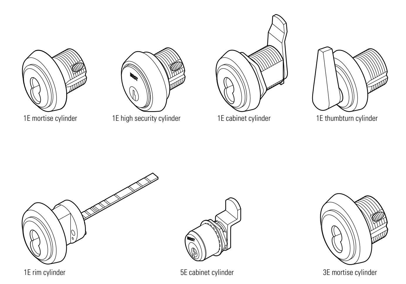
Figure 1.1 E Series product family diagram
CERTIFICATIONS AND STANDARDS
- The 1E7J4 high security cylinder is listed by Underwriter's Laboratories when used with 36H/37H mortise locks.
- The 1E74 mortise cylinder complies with ANSI/BHMA, Grade 2 standards when used with 30H Series mortise locks and the 1CD core.
- The 1E74 mortise cylinder complies with ANSI/BHMA, Grade 3 standards when used with the standard 1C core.
1–2 E Series Service Manual
DOCUMENTATION PACKAGE
The following resources are available to help you with the installation, start-up, and maintenance of your BEST E Series product.
These documents can be ordered separately from the product:
| Documentation Title | Doc. No. |
|---|---|
| BEST Installation Instructions for 1E Mortise Cylinders | T61781 |
| BEST Installation Instructions for 1E Rim Cylinders | T61971 |
| H Series Service Manual | T61964 |
| Best Adaptation & Equivalent List (8th edition) | B120–1 |
| Core and Key Service Manual | T35527 |
TECHNICAL SUPPORT
Support services
When you have a problem with an E Series product, your first resource for help is the E Series Service Manual . If you cannot find a satisfactory answer, contact your local BEST Representative.
Telephone and web technical support
A factory-trained Certified Product Specialist (CPS) is available in your area whenever you need help. Before you call, however, please make sure you are where the E Series product is, and that you are prepared to give the following information:
- what happened and what you were doing when the problem arose
- what you have done so far to solve the problem.
Best Access Systems Representatives provide telephone technical support for all E Series products. You may locate the representative nearest you by calling (317) 849-2250 Monday through Friday, between 7:00 a.m. and 4:00 p.m. eastern standard time; or visit the web site, www.BestAccess.com.
1–4 E Series Service Manual
2 PARTS FOR 1E SERIES
The following pages contain exploded diagrams that show all field serviceable parts for common 1E Series mortise, rim, and cabinet cylinders. This chapter also contains diagrams of special application mortise cylinders, diagrams of trim and other miscellaneous parts, and diagrams of common cams.
2–2
EXPLODED DIAGRAMS AND PARTS LISTS MORTISECYLINDER
|
I
te m |
Pa
t n r o. |
Q
ty |
De
ip io t sc r n |
|---|---|---|---|
| 1 |
6
A 0 8 3 1 |
1 |
6-p
fo Sp in ac er r co re s |
| 2 |
4
A 5 0 0 9 |
2 |
T
hr in ow p |
| 3 |
A
1 0 3 9 0 |
1 |
T
hr lu ow p g |
| 4 |
A
1 0 3 9 1 |
1 |
d
he d Sta m p e a |
| 5 |
4
C 3 0 7 5 |
1 |
l
de 7-p in in r cy |
| 6 |
Se
2– 1 0 e p ag e |
1 |
l
de Cy in in r r g |
| 7 |
Se
2– 1 5 e p ag e |
1 |
†
4 ho Ca ( C ) m n s w |
| 8 |
4
A 3 1 2 3 |
1 |
Se
t s cr ew |
† Specify cylinder length when ordering cams. Cylinders 2 inches or longer require a thumbturn cam. See Appendix B for available thumbturn cams.
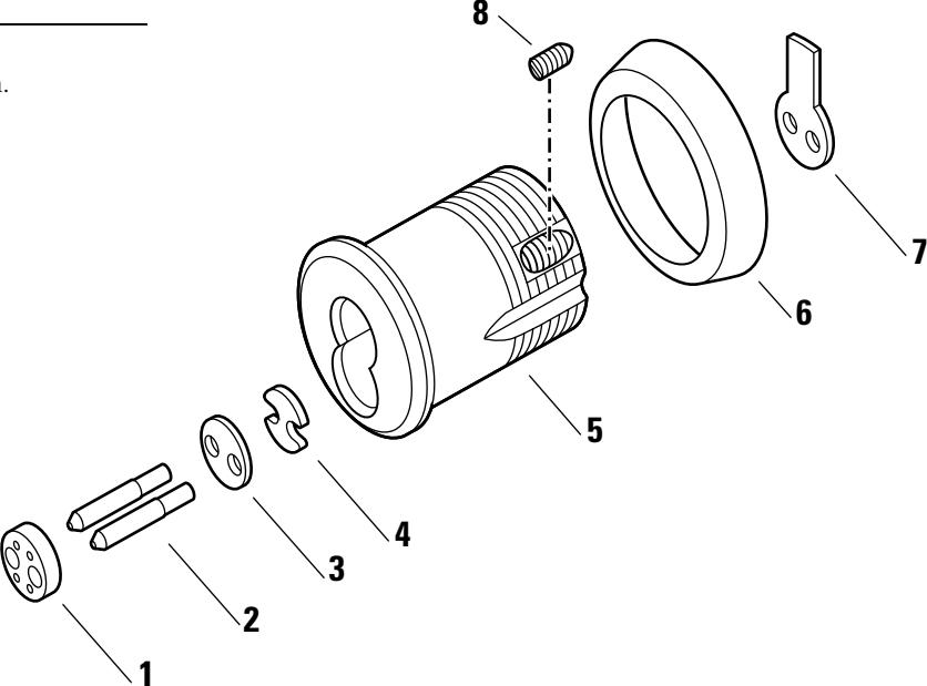
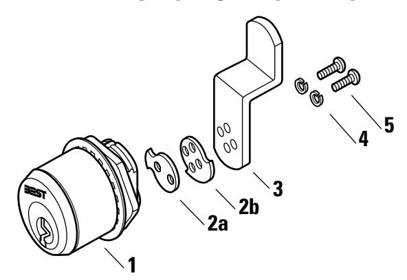
Figure 2.1 1E74 mortise cylinder exploded view
RIMCYLINDER
|
I
te m |
Pa
t n r o. |
Q
ty |
De
ip io t sc r n |
|---|---|---|---|
| 1 |
6
A 0 8 3 1 |
1 |
6-p
fo Sp in ac er r co re s |
| 2 |
1
1 C 0 0 2 |
1 |
l
de 7-p in in cy r |
| 3 |
Se
2– 1 0 e p ag e |
1 |
l
de Cy in in r r g |
| 4 |
4
A 0 1 1 0 |
1 |
T
hr lu b ly p m ow g as se |
| 5 |
4
A 0 1 0 0 |
1 |
d
le Sp in |
| 6 |
4
B 0 1 0 9 |
1 |
hr
T lu in ta p ow g re er |
| 7 |
4
A 1 5 5 3 |
2 |
Re
in ta er sc re w |
| 8 |
C
1 3 9 1 0 |
1 |
C
lam lat p p e |
| 9 |
4
4 5 A 0 8 |
2 |
M
in nt ou g sc re w |
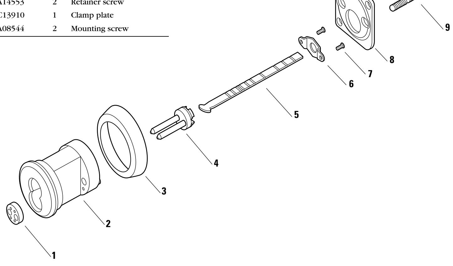
Figure 2.2 1E72 rim cylinder exploded view
THUMBTURNCYLINDER
|
I
te m |
Pa
t n r o. |
Q
ty |
De
ip io t sc r n |
|---|---|---|---|
| 1 |
6
B 1 5 7 2 |
1 |
hu
bt A D A t m ur n |
|
ho
t s no n w |
4
4 6 A 2 0 |
1 |
hu
bt No A D A t n- m ur n |
| 2 |
6
A 0 3 1 2 |
1 |
lu
Sp in p r g g |
| 3 |
A
1 8 0 3 3 |
1 |
Sp
in r g |
| 4 |
4
B 0 7 8 1 |
1 |
de
7-p in l in cy r |
| 5 |
2–
1 0 Se e p ag e |
1 |
l
de Cy in in r r g |
| 6 |
Se
B– 2 p e ag e |
1 |
4
( 1 ho ) Ca C 3 s m w n |
| 7 |
4
A 0 8 3 8 |
2 |
Ca
m sc re w |
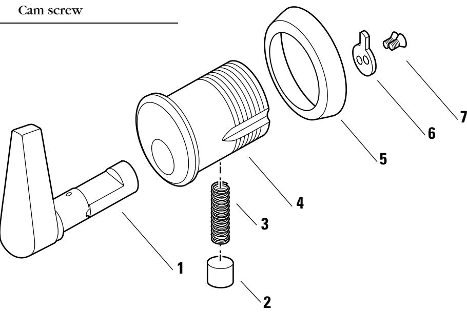
Figure 2.3 1E7A4 thumbturn cylinder exploded view
| ltem | Part no. | Qty. | Description |
|---|---|---|---|
| 1 | A06831 | 1 | Spacer for 6-pin cores |
| 2 | A00539 | 2 | Throw pin |
| 3 | A07544 | 1 | Throw plug |
| 4 | B07547 | 1 | 7-pin cylinder |
| 5 | See page 2-10 | 1 | Cylinder ring |
| 6 | A00836 | 1 | Nut |
| 7 | A04460 | 1 | Throw plug retainer |
| 8 | See page 2-20 | 1 | Cam † (C228 shown) |
| 9 | A07542 | 2 | Cam screw |
LOST MOTION CABINET CYLINDER
| Item | Part no. | Qty. | Description |
|---|---|---|---|
| 1 | A06831 | 1 | Spacer for 6-pin cores |
| 2 | A07986 | 1 | Throw member assembly |
| 3 | A07993 | 1 | 7-pin cylinder |
| 4 | See page 2-10 | 1 | Cylinder ring |
| 5 | A00836 | 1 | Nut |
| 6 | B40412 | 1 | Cam stop pin |
| 7 | See page 2-20 | 1 | Cam with drive pin † (C229 shown) |
| 8 | A07988 | 1 | Cam driver |
| 9 | A07954 | 1 | Washer |
| 10 | A07956 | 1 | Cam screw |
† See page 5-17 for cam rotations.
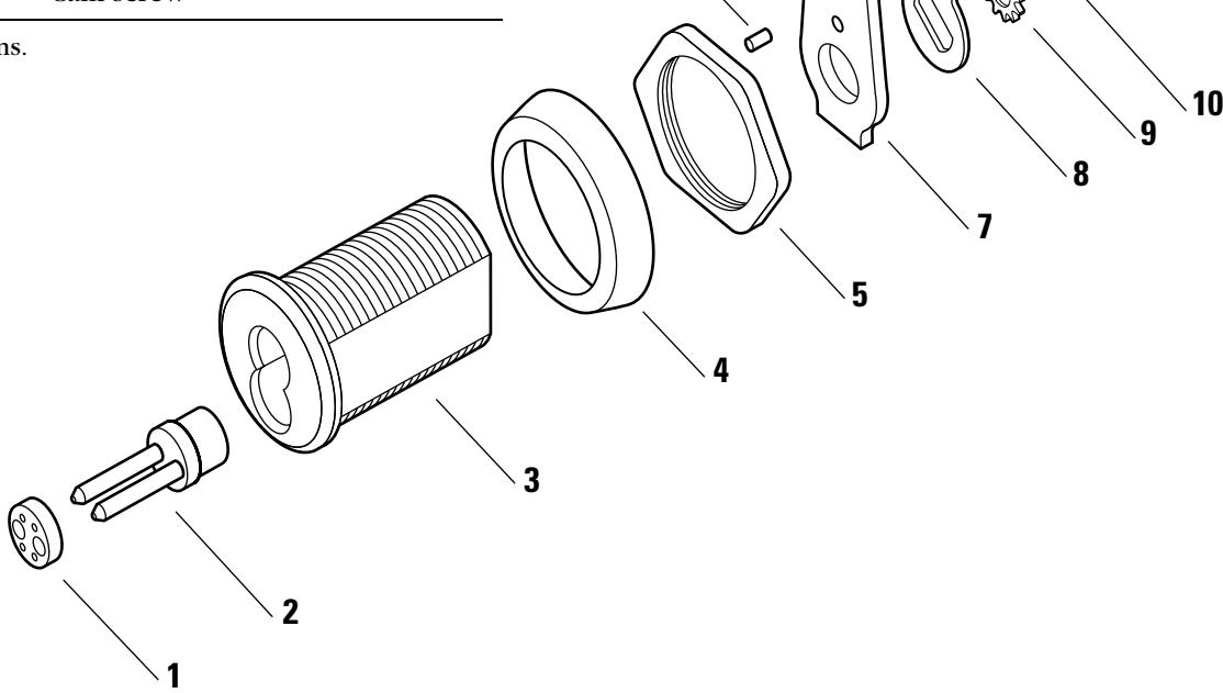
Figure 2.5 1E7E4 lost motion cabinet cylinder exploded view
SPECIAL MORTISE CYLINDER APPLICATIONS
Dust cover cylinder
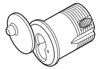
Figure 2.6 1E7B4 dust cover cylinder
Wrench-resistant cylinder
Note: See page 2–12 for wrench-resistant cylinder rings.
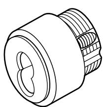
Figure 2.7 1E7C4 wrench-resistant cylinder
Lost motion cylinder Note: Specify cylinder handing when ordering (for example, "RHI" = right hand, inside door).
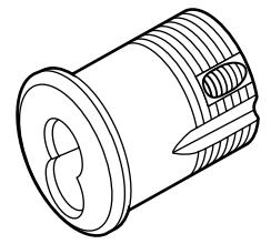
Figure 2.8 1E7F4 lost motion cylinder
Hotel shifting cam cylinder
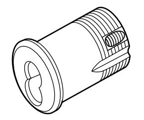
Figure 2.9 1E7G4 hotel cylinder
Non-UL high security cylinder
Note: To order the 1E7J4 high security cylinder listed by Underwriters Laboratories (UL), contact your BEST Representative.
Note: High security cylinders require long blade keys for operation.
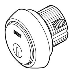
Figure 2.10 1E7K4 non-UL high security cylinder
Tapered-head cylinder
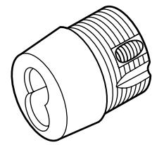
Figure 2.11 1E76 tapered-head cylinder
TRIM PARTS
Rim dummy trim
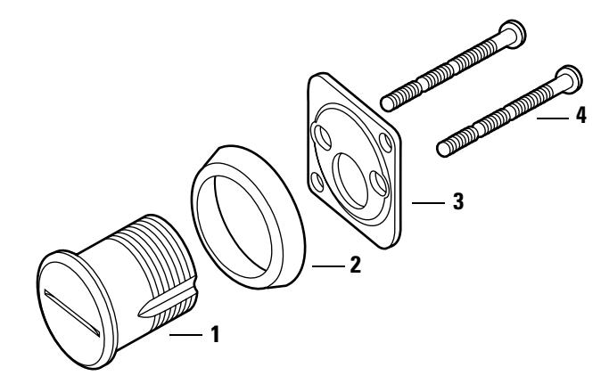
Figure 2.12 1E02 rim cylinder dummy trim
Rim dummy trim parts list
| Item | Part no. | Qty. | Description |
|---|---|---|---|
| 1 | A05032 | 1 | Dummy cylinder |
| 2 | See page 2–10 | 1 | Cylinder ring |
| 3 | C13910 | 1 | Clamp plate |
| 4 | A08544 | 2 | Mounting screw |
Mortise dummy trim
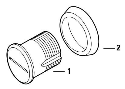
Figure 2.13 1E04 mortise cylinder dummy trim
Mortise dummy trim parts list
| Item† | Part no. | Qty. | Description |
|---|---|---|---|
| 1 | A05032 | 1 | Dummy cylinder |
| 2 | See page 2–10 | 1 | Cylinder ring |
† The C13910 clamp plate and two A08544 mounting screws for rim dummy trim applications are also included in the mortise dummy trim package.
Stamped cylinder rings
A cylinder ring is required if there is a gap between the cylinder head and the mounting surface when the cam is positioned for proper lock operation. Stamped cylinder rings may be stacked, if necessary, for some door applications.
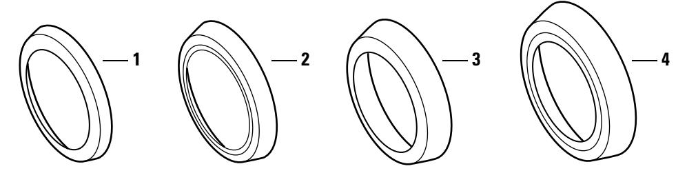
Figure 2.14 Standard cylinder rings
Stamped cylinder rings parts list
| Item |
Nomen
clature |
Part no. | Length |
|---|---|---|---|
| 1 | 1E-R2 | A40102 | 1/8″ |
| 2 | 1E-R3 | A40103 | 3/16″ |
| 3 | 1E-R4 | A40104 | 1/4″ |
| 4 | 1E-R5 | A40105 | 3/8″ |
Stamped cylinder ring packages
| Nomen | |
|---|---|
| clature | Rings included |
| RP† |
1E-R3—3/16″
1E-R5—3/8″ |
| RP1 |
1E-R2—1/8″
1E-R3—3/16″ |
| RP2 |
1E-R2—1/8″
1E-R4—1/4″ |
| RP3‡ |
1E-R2—1/8″
1E-R4—1/4″ 1E-R5—3/8″ |
† Supplied standard with 7-pin rim cylinders.
‡ Supplied standard with 7-pin mortise cylinders.
Straight cylinder rings
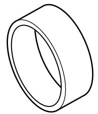
Figure 2.15 Straight cylinder ring (1E-R708 shown)
Straight cylinder ring part numbers
|
Nomen
clature |
Part no. | Length |
|---|---|---|
| 1E-R702 | A06280 | 1/8″ |
| 1E-R703 | A06281 | 3/16″ |
| 1E-R704 | A06282 | 1/4″ |
| 1E-R705 | A04370 | 5/16″ |
| 1E-R706 | A06283 | 3/8″ |
| 1E-R707 | A06284 | 7/16″ |
| 1E-R708 | A06285 | 1/2″ |
| 1E-R709 | A04369 | 9/16″ |
| 1E-R710 | A06286 | 5/8″ |
| 1E-R711 | A06288 | 11/32″ |
| 1E-R712 | A06287 | 3/4″ |
Wrench-resistant cylinder rings
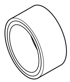
Figure 2.16 Wrench-resistant cylinder ring (1E-R808 shown)
Wrench-resistant cylinder ring part numbers
| Nomen | ||
|---|---|---|
| clature | Part no. | Length |
| 1E-R802 | A05963 | 1/8″ |
| 1E-R803 | A05958 | 3/16″ |
| 1E-R804 | A05959 | 1/4″ |
| 1E-R805 | A05960 | 5/16″ |
| 1E-R806 | A05961 | 3/8″ |
| 1E-R807 | A05962 | 7/16″ |
| 1E-R808 | A05957 | 1/2″ |
| 1E-R809 | A05964 | 9/16″ |
| 1E-R810 | A05965 | 5/8″ |
| 1E-R811 | A05966 | 11/16″ |
| 1E-R812 | A05967 | 3/4″ |
| 1E-R814 | A05969 | 13/16″ |
| 1E-R815 | A05970 | 7/8″ |
| 1E-R816 | A05971 | 15/16″ |
Mounting plates
The following mounting plates can be used with 1E7D4 and 1E7E4 cabinet cylinders.
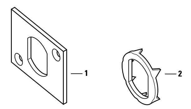
Figure 2.17 Mounting plates
Mounting plates part numbers
| Item | Part no. | Description |
|---|---|---|
| 1 | A14543 | Large mounting plate |
| 2 | A20361 | Wood mounting plate |
Tools The following tools are used to install and service 1E Series cylinders.
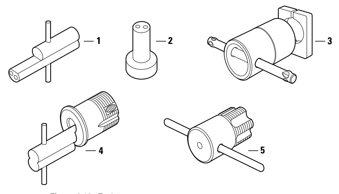
Tools parts list Figure 2.18 Tools
| Nomen– | ||||
|---|---|---|---|---|
| Item | clature | Part no. | Description | Use |
| 1 | ED211 | A09612 | Mortise cylinder wrench |
Tool for installing, removing, and
testing cylinders |
| 2 | ED212 | A19370 | Mortise cylinder cam assembly tool |
Tool for assembling cams to mortise
cylinders |
| 3 | ED221 | A06206 | Mortise cylinder thread repair die |
Tool for rethreading 1 5/32"
cylinders |
| 4 | ED222 | A06399 | Cylinder cam testing tool |
Tool for testing the functionality of
cams when installed in a door |
| 5 | ED225 | A01474 | 1E cylinder hole tap | Tool for rethreading case threads |
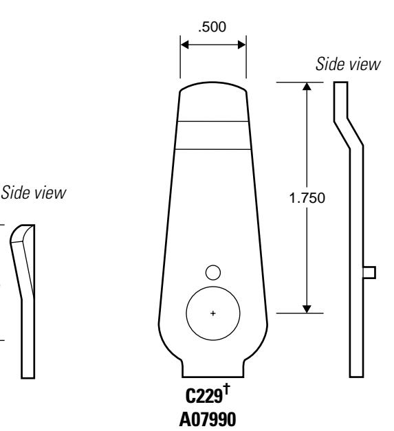
CAM IDENTIFICATION
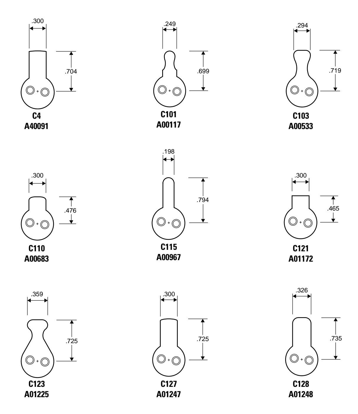
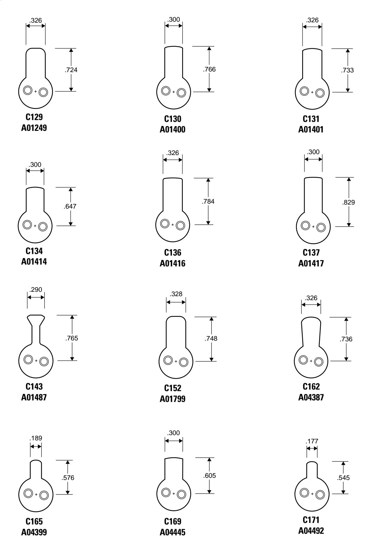
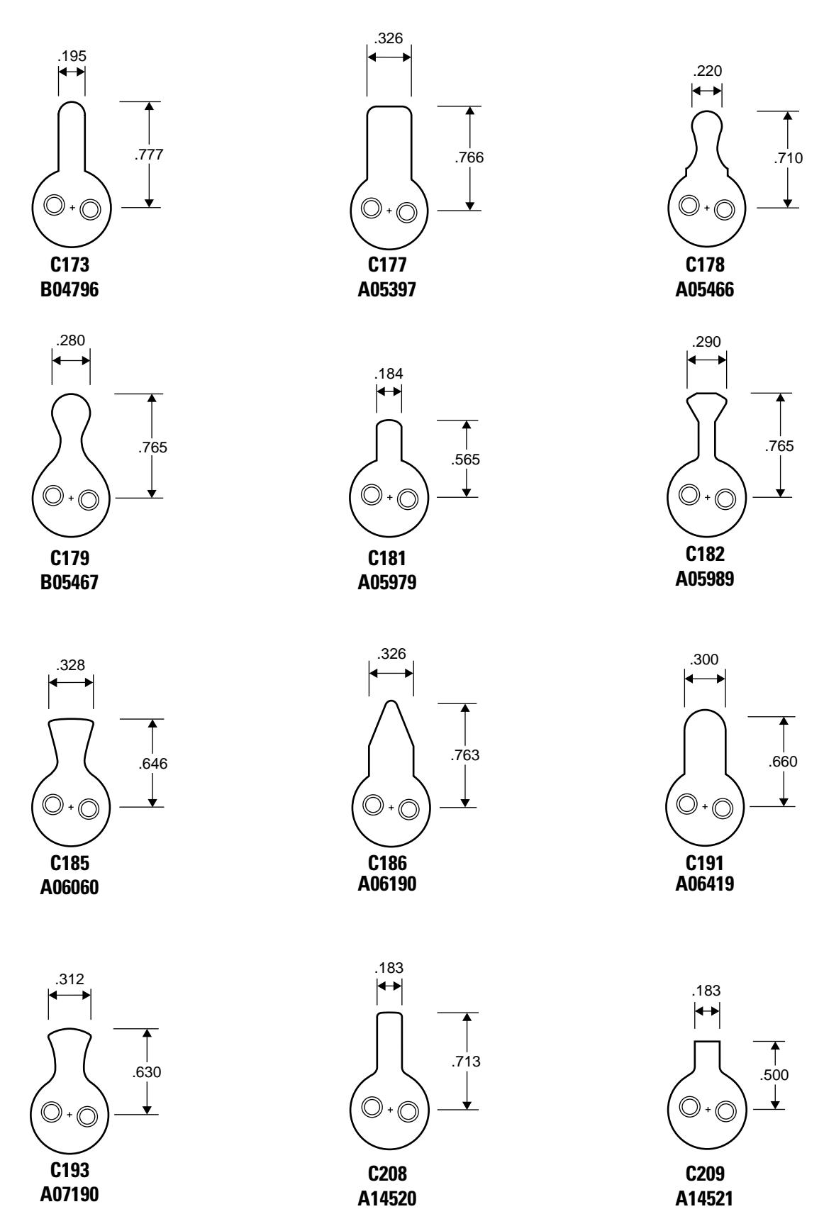
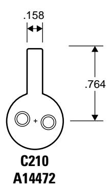
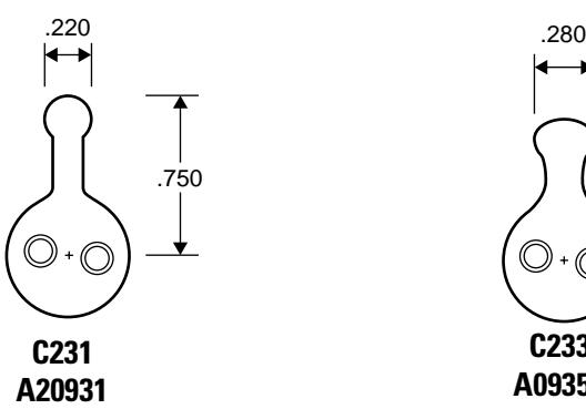
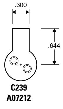
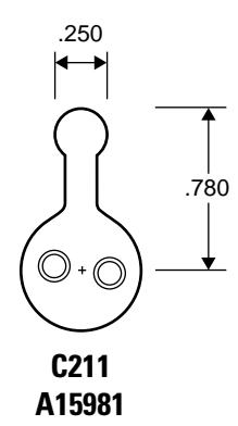
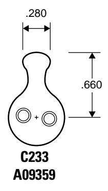
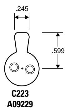
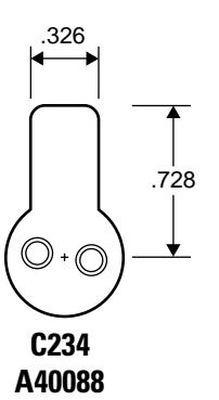
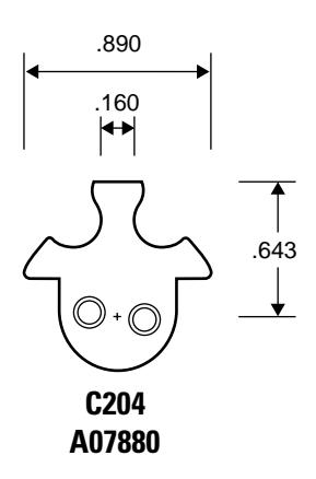
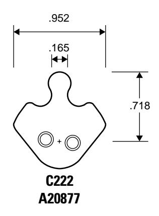
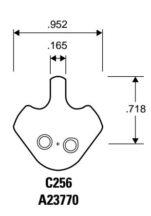
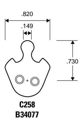
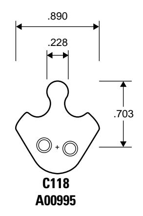
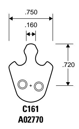
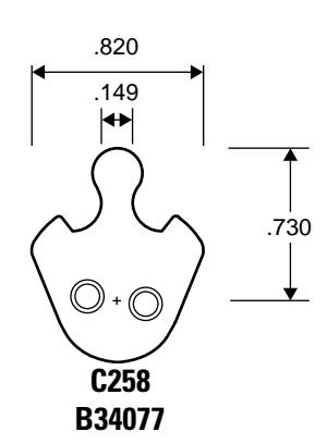
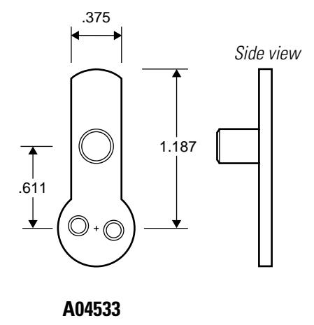
The following common cams are grouped by shape and then sorted by cam number, listing dimensions in inches for each. All cams are shown approximately their size. See Appendix A Cams Table for a table of E Series cams listed by part number.
Note: Specify "1E" when ordering cams separately (for example, "1E-C4").
Straight cams
Straight cams cont'd.
Straight cams cont'd.
Straight cams cont'd.
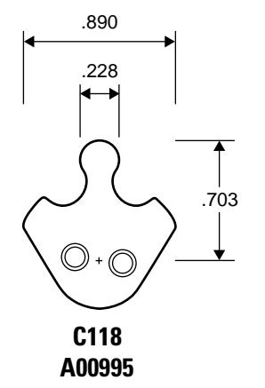
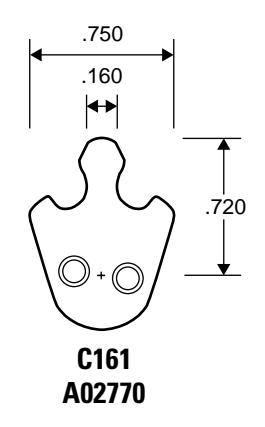
Cloverleaf cams
Cabinet cams
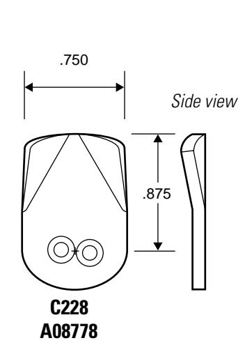
† Drive pin location shown.
Cabinet cams cont'd.
Cabinet cams cont'd.

- † Specify cam length "X" when ordering. See the table below. See page 5–16 for 1E Series cam rotations.
- ‡ Drive pin hole location shown.
| Cam | Part No. | Length "X" |
|---|---|---|
| C500 | A63060 | 1 1/8″ |
| C501 | A63061 | 1 1/2″ |
| C502 | A63062 | 2 1/4″ |
| C503 | A63063 | 1 1/8″ |
| C504 | A63064 | 1 1/2″ |
| C505 | A63065 | 2 1/4″ |
| C506 | A63066 | 1 1/8″ |
| C507 | A63067 | 1 1/2″ |
| C508 | A63068 | 2 1/4″ |
X
Roller cams
Two-point cams
3 PARTS FOR 3E SERIES
The following pages contain an exploded diagram showing all field serviceable parts for the 3E Series mortise cylinder, diagrams of trim and other miscellaneous parts, and diagrams of common cams.
M ORTISE CYLINDER EXPLODED DIAGRAM AND PARTS LIST
| Part no. | Qty. | Description |
|---|---|---|
| A06831 | 1 | Spacer for 6-pin cores |
| A40095 | 2 | Throw pin |
| A10390 | 1 | Throw plug |
| A10391 | 1 | Stamped head |
| C40090 | 1 | 7-pin cylinder |
| See page 3-3 | 1 | Cylinder ring |
| See page 3-4 | 1 | Cam (C3 shown) |
| A34123 | 1 | Set screw |
|
A06831
A40095 A10390 A10391 C40090 See page 3-3 See page 3-4 |
A06831 1 A40095 2 A10390 1 A10391 1 C40090 1 See page 3-3 1 See page 3-4 1 |
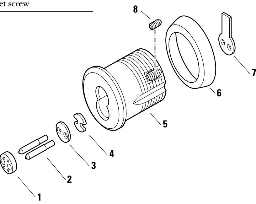
Figure 3.1 3E74 mortise cylinder exploded view
TRIM PARTS
Stamped cylinder rings
A cylinder ring is required if there is a gap between the cylinder head and the mounting surface when the cam is positioned for proper lock operation. Stamped cylinder rings may be stacked, if necessary, for some door applications.
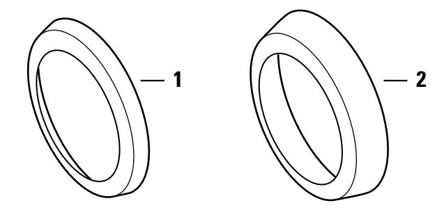
Figure 3.2 Cylinder rings
Cylinder rings parts list
| Nomen | |||
|---|---|---|---|
| Item | clature | Part no. | Length |
| 1 | 3E-R2 | A40106 | 1/8″ |
| 2 | 3E-R4 | A40107 | 1/4″ |
| not shown | 3E-R8 | A09198 | 3/8″ |
Tools
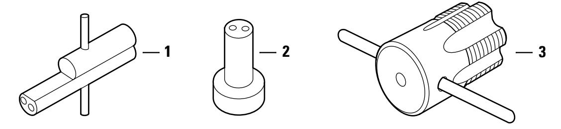
Figure 3.3 Tools
Tools parts list
| Nomen– | ||||
|---|---|---|---|---|
| Item | clature | Part no. | Description | Use |
| 1 | ED211 | A09612 | Mortise cylinder wrench |
Tool for installing, removing, and
testing cylinders |
| 2 | ED212 | A19370 | Mortise cylinder cam assembly tool |
Tool for assembling cams to mortise
cylinders |
| 3 | ED224 | A07861 | 3E cylinder hole tap | Tool for rethreading case threads |
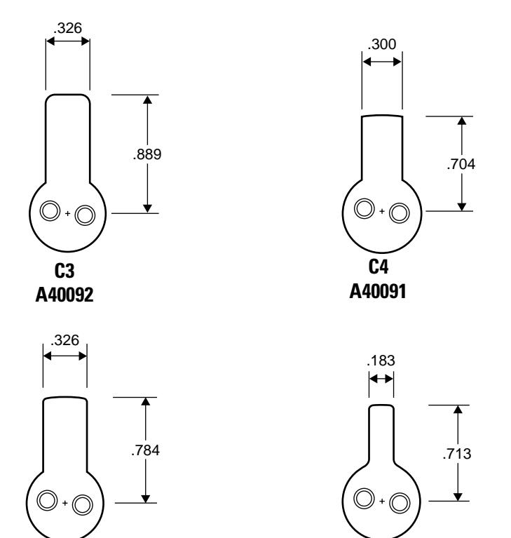
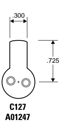
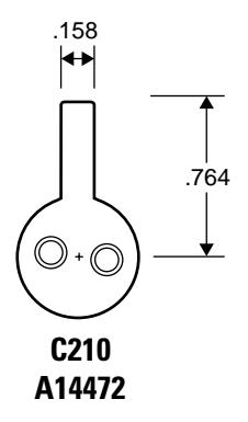
CAM IDENTIFICATION
The following section shows common 3E cams and their dimensions in inches. Cams are shown approximately their size. See Appendix A E Series Cams Table for a list of E Series cams sorted by part number.
Note: Specify "3E" when ordering cams separately (for example, "3E-C3").
Straight cams
Cloverleaf cams
C136 A01416
C208 A14520
Roller cams
3–6 E Series Service Manual
4 PARTS FOR 5E SERIES
The following pages contain exploded diagrams showing all field serviceable parts for the 5E Series cylinders, diagrams of trim and other miscellaneous parts, and drawings of common cams.
4-2
EXPLODED DIAGRAM AND PARTS LIST LOST MOTION CABINET CYLINDER
| ltem | Part no. | Qty. | Description |
|---|---|---|---|
| 1 | C10861 | 1 | 7-pin cylinder and plug assembly † |
| 2 | A12350 | 2 | Groove pin |
| 3 | B10852 | 1 | Slide cap for 7-pin cylinders |
| 4 | See page 4-5 | 1 | Cylinder ring |
| 5 | A21068 | 1 | Lock washer |
| 6 | A08049 | 1 | Nut |
| 7 | A21150 | 1 | Throw plug |
| 8 | See page 4-7 | 1 | Cam ‡ (C4A shown) |
| 9 | A21099 | 1 | Drive pin |
| 10 | A21151 | 1 | Cam driver |
| 11 | A14045 | 2 | Washer |
| 12 | A04845 | 2 | Screw |
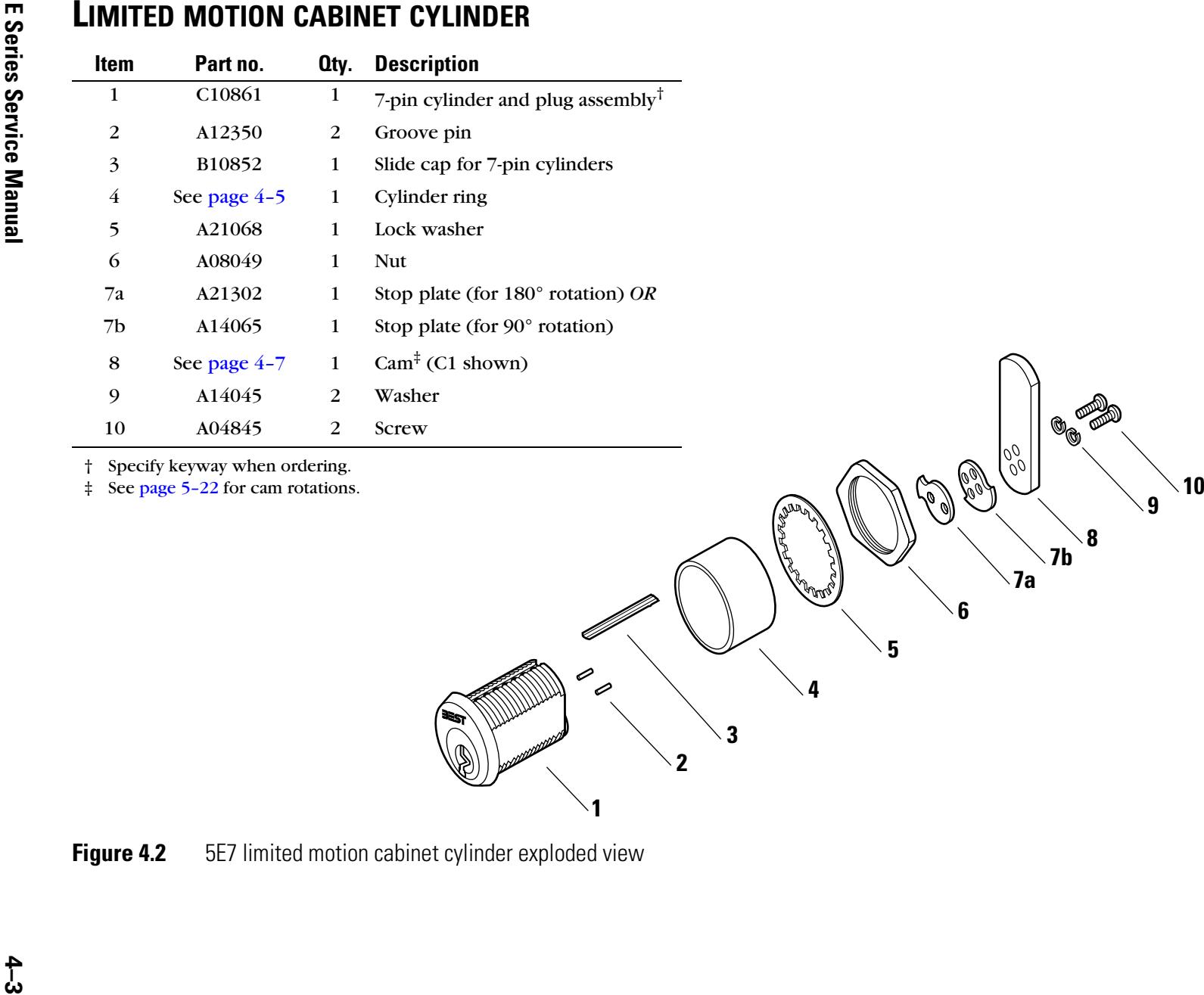
† Specify keyway when ordering.
‡ See page 5-18 for cam rotations.
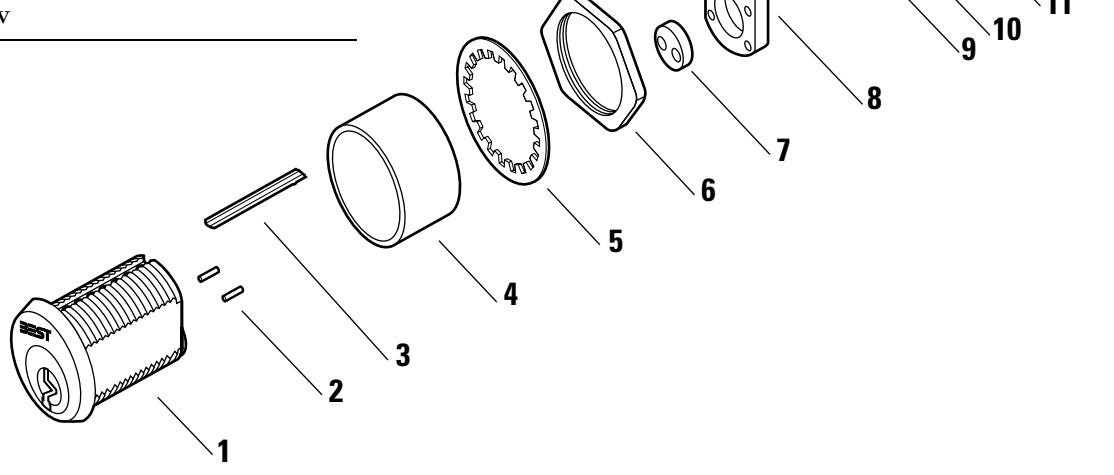
Figure 4.1 5E7 lost motion cabinet cylinder exploded view
| ltem | Part no. | Qty. | Description |
|---|---|---|---|
| 1 | C10861 | 1 | 7-pin cylinder and plug assembly † |
| 2 | A12350 | 2 | Groove pin |
| 3 | B10852 | 1 | Slide cap for 7-pin cylinders |
| 4 | See page 4-5 | 1 | Cylinder ring |
| 5 | A21068 | 1 | Lock washer |
| 6 | A08049 | 1 | Nut |
| 7a | A21302 | 1 | Stop plate (for 180° rotation) OR |
| 7b | A14065 | 1 | Stop plate (for 90° rotation) |
| 8 | See page 4-7 | 1 | Cam ‡ (C1 shown) |
| 9 | A14045 | 2 | Washer |
| 10 | A04845 | 2 | Screw |
TRIM PARTS
Cylinder rings Determining the ring length for 5E7 cylinders
A cylinder ring is required if there is a gap between the cylinder head and the mounting surface when the cam is positioned for proper lock operation. To determine what length cylinder ring is needed, see Figure 4.3 and perform the following steps:
- 1. Measure in inches the thickness of the mounting surface. See length "A" in Figure 4.3.
- 2. Measure in inches the desired distance from the cam to the inside of the mounting surface. See length "B" in Figure 4.3.
- 3. Add together the measurement for "A" from Step 1 and the measurement for "B" from Step 2.
For straight cams: X = 1 1/8 ″ – (A + B) For inward cams: X = 1 13/16 ″ – (A + B)
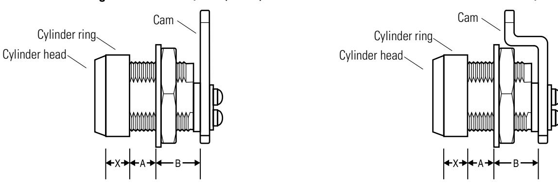
For outward cams: X = 1 7/16 ″ – (A + B)
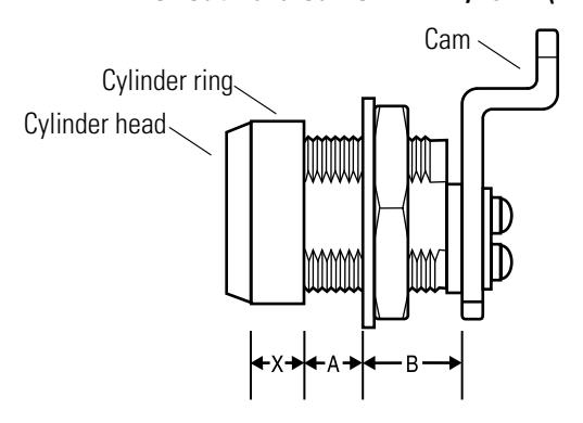
Figure 4.3 Determining the cylinder ring length
4. For straight cams , subtract the total in Step 3 from 1 1/8″. The difference is the length of the cylinder ring needed. See straight cam length "X" in Figure 4.3.
For inward mounted cams , subtract the total in Step 3 from 1 13/16″. The difference is the length of the cylinder ring needed. See inward cam length "X" in Figure 4.3.
For outward mounted cams , subtract the total in Step 3 from 1 7/16″. The difference is the length of the cylinder ring needed. See inward cam length "X" in Figure 4.3.
See the parts table below for available cylinder ring lengths.
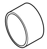
Figure 4.4 Cylinder ring (R708 shown)
Cylinder ring part numbers
|
Nomen
clature |
Part no. | Length |
|---|---|---|
| 5E-R701 | A10253 | 1/16″ |
| 5E-R702 | A10250 | 1/8″ |
| 5E-R703 | A10260 | 3/16″ |
| 5E-R704 | A10257 | 1/4″ |
| 5E-R705 | A10265 | 5/16″ |
| 5E-R706 | A10263 | 3/8″ |
| 5E-R707 | A10266 | 7/16″ |
| 5E-R708 | A10258 | 1/2″ |
| 5E-R709 | A10269 | 9/16″ |
| 5E-R710 | A10256 | 5/8″ |
| 5E-R711 | A10268 | 11/16″ |
| 5E-R712 | A10267 | 3/4″ |
Mounting plates
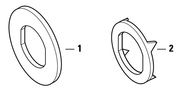
Figure 4.5 Mounting plates
Mounting plates part numbers
| Item | Part no. | Qty. | Description |
|---|---|---|---|
| 1 | A14533 | 1 | Round mounting plate |
| 2 | A14534 | 1 | Wood mounting plate |
Tools
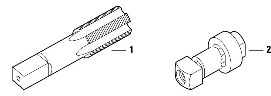
Figure 4.6 Tools
Tools parts list
| Nomen | |||||
|---|---|---|---|---|---|
| Item | clature | Part no. | Qty. | Description | Use |
| 1 | 5ED253 | A14053 | 1 | 5E cylinder hole tap | Tool for rethreading case threads |
| 2 | 5ED254 | BT-21071 | 1 | SE-5E 3/4″ metal punch die |
Tool for punching cabinet holes for
cylinder installation |
4–6 E Series Service Manual
CAM IDENTIFICATION
The following section shows common 5E cams and their dimensions in inches. See Appendix A Cams Table for a list of E Series cams sorted by part number.
Note: Specify "5E" when ordering cams separately (for example, "5E-C2A").
Note: For 5E cam rotations, see page 5–18.
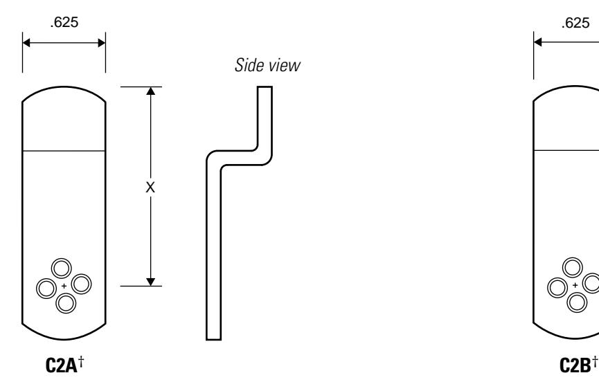
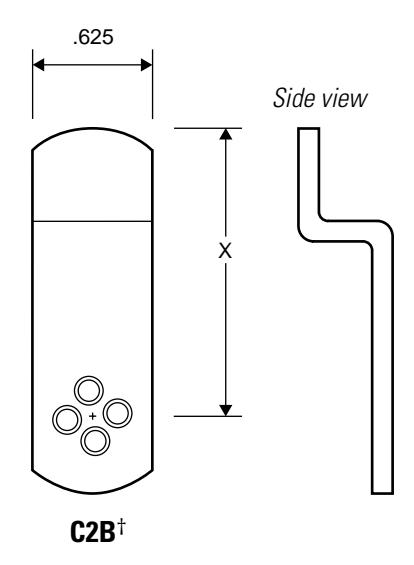
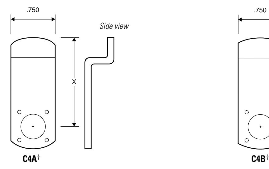
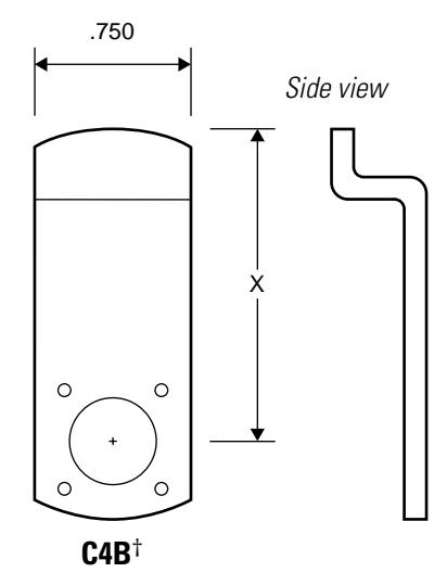
† Specify cam length when ordering. See the BEST Catalog for available cam lengths.
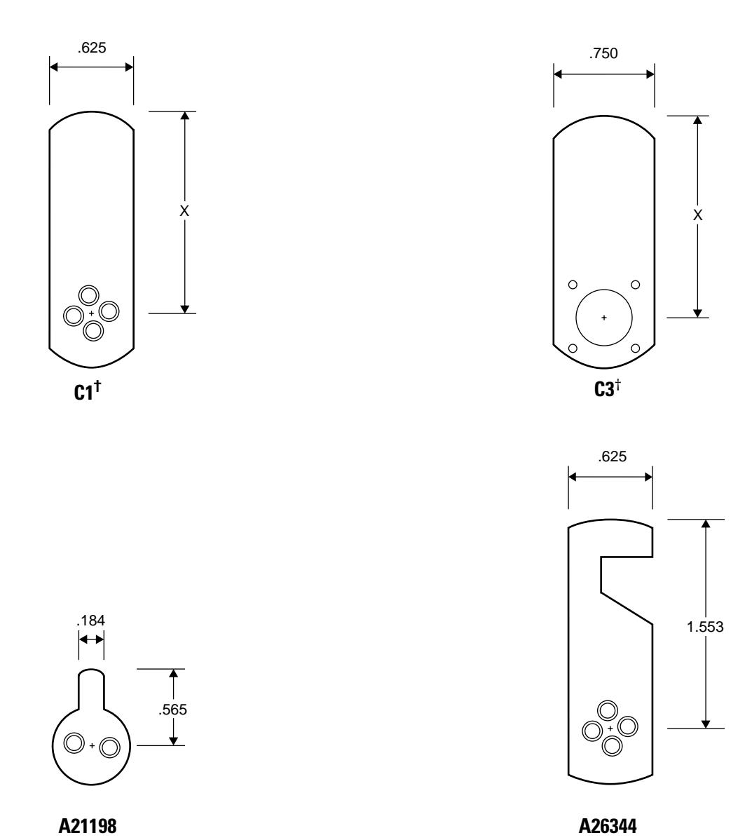
† Specify cam length "X" when ordering. See the BEST Catalog for available cam lengths.
4–8 E Series Service Manual
5 SERVICE AND MAINTENANCE
This chapter contains instructions for replacing components, servicing and maintaining components, and troubleshooting common problems for the 1E Series, 3E Series, and 5E Series cylinders.
| To | See page |
|---|---|
| Replace mortise cylinders | 5–2 |
| Replace rings | 5–7 |
| Replace riveted cams | 5–8 |
| Replace rim cylinders | 5–10 |
| Replace spindles | 5–12 |
| Replace cabinet cylinders | 5–13 |
| View 1E Series cam rotations | 5–16 |
| View 5E Series cam rotations | 5–18 |
| Troubleshoot problems | 5–25 |
REPLACING PARTS
Replacing the standard mortise cylinder
For information about servicing your BEST mortise lock case, see the H Series Service Manual [T61964].
To remove the mortise cylinder:
- 1. Unscrew the two faceplate screws and remove the faceplate from the lock case.
- 2. Insert the control key into the core and rotate the key 15 degrees to the right. Remove the core.
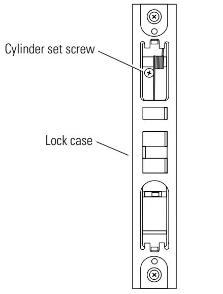
- 3. Loosen the cylinder set screw, found on the inside of the lock case. See Figure 5.1.
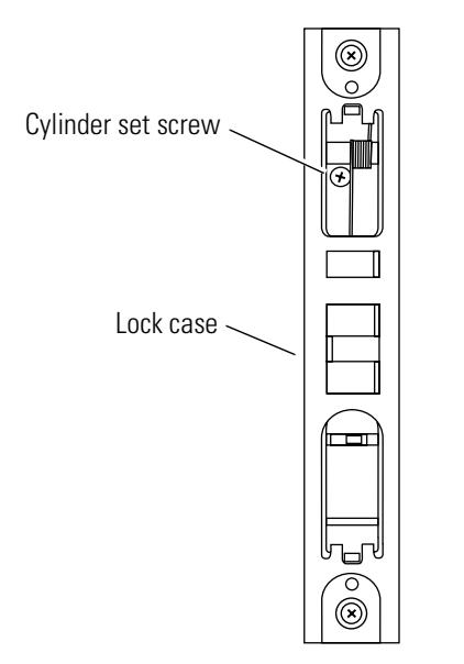
View from the edge of the door
Figure 5.1 Location of the cylinder set screw
4. Using a narrow-bladed screwdriver, insert the blade into the figure-8 opening and back the small set screw into the cylinder until the tip of the screw is below the threads of the cylinder.
5. Insert the mortise cylinder wrench into the cylinder unscrew the cylinder from the lock mortise case. See Figure 5.2.
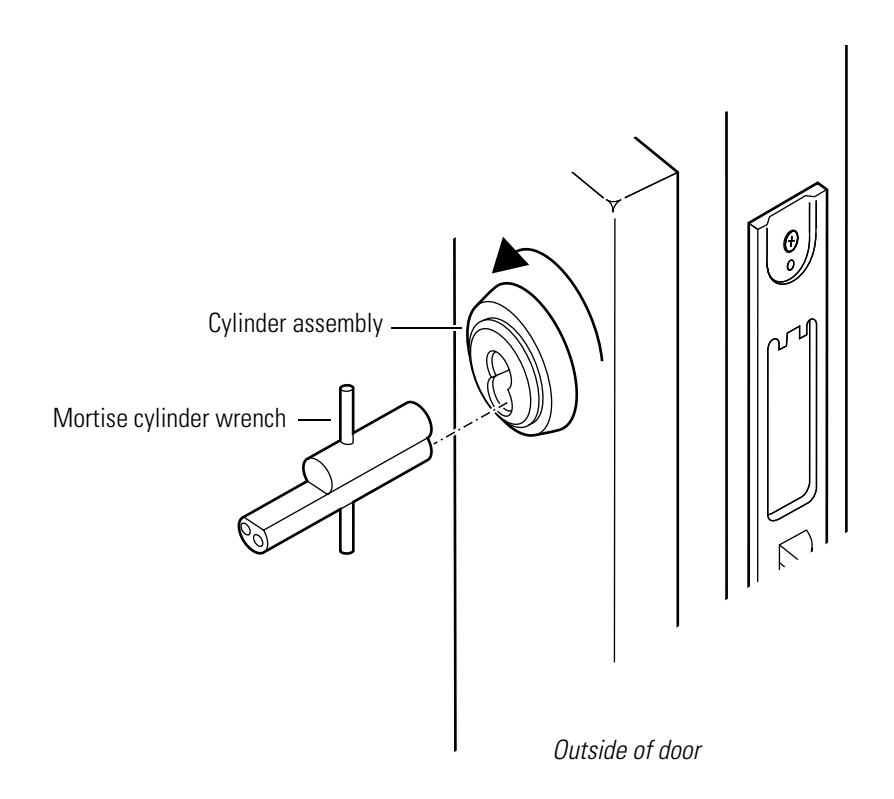
Figure 5.2 Removing the mortise cylinder
- 6. Slide the cylinder assembly out of the door.
- 7. If the lock is double-keyed, repeat steps 2 through 6 for the other cylinder.
To reinstall the mortise cylinder:
-
1.
If installing a new cylinder
:
- a. From the outside of the cylinder, thread the slotted head of the set screw into the cylinder. See Figure 5.3.
- b. Using a narrow-blade screwdriver, insert the blade into the cylinder's figure-8 opening and back the set screw into the cylinder until the tip of the set screw is below the threads of the cylinder.
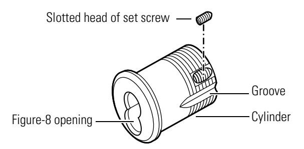
Figure 5.3 Threading the set screw
- 2. Place the cylinder ring, if used, on the cylinder.
- 3. From the back end of the cylinder, rotate the cam to the 12 o'clock position. See Figure 5.4.
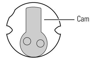
Figure 5.4 Back view of cam in 12 o'clock position
4. With the mortise cylinder wrench inserted into the figure-8 opening, insert the cylinder assembly into the cylinder hole on the outside of the door. See Figure 5.5.
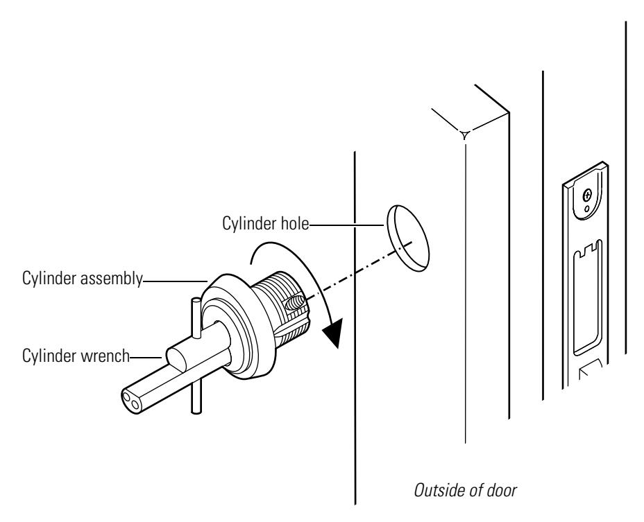
Figure 5.5 Reinstalling the mortise cylinder
5. For standard cylinders , screw the cylinder into the lock case until the cylinder ring is flush against the door.
For concealed cylinders , screw the cylinder into the lock case until the groove around the cylinder head is even with the door surface.
For high security cylinders , screw the cylinder into the lock case until the cylinder head touches the inside rim of the cylinder ring.

Be careful not to cross-thread the cylinder during the rotation process to avoid jamming the cylinder in the door.
Do not screw the cylinder in too tightly. Doing so may cause you or someone else to be locked out.
6. Using a narrow-blade screwdriver, insert the blade into the figure-8 opening and tighten the small set screw (installed in the cylinder) into the lock case.
7. Tighten the cylinder set screw, found on the inside of the lock case, into the cylinder groove (see Figure 5.3 for the location of the cylinder groove). See Figure 5.6.
View from the edge of the door
Figure 5.6 Location of the cylinder set screw (view from the edge of the door)
- 8. Insert the control key and core into the cylinder. Rotate the control key 15 degrees counterclockwise and then remove the key.
- 9. If the lock is double-keyed, repeat steps 1 through 8 for the other cylinder.
- 10. Position the faceplate on the lock case and reinstall the two faceplate screws.
- 11. Lock and unlock the door to be sure the cylinder is properly installed.
Replacing the cylinder ring
To remove the cylinder ring:
1. For mortise cylinders , remove the faceplate from the lock case and the cylinder assembly from the door ( page 5–2) .
For rim cylinders , remove the cylinder assembly from the door (page 5–10) .
For cabinet cylinders , remove the cylinder assembly from the cabinet door ( page 5–13) .
2. Slide the cylinder ring off of the cylinder assembly. See Figure 5.7.
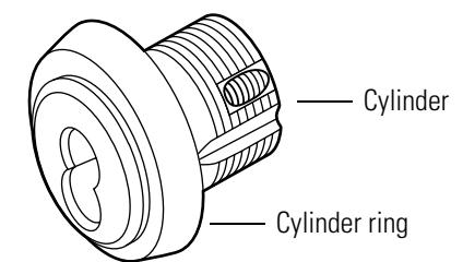
Figure 5.7 Removing the cylinder ring (mortise cylinder shown)
To reinstall the cylinder ring:
- 1. Select a cylinder ring that will position the cylinder assembly to the correct length in the door.
- 2. Slide the cylinder ring onto the cylinder assembly. See Figure 5.8.
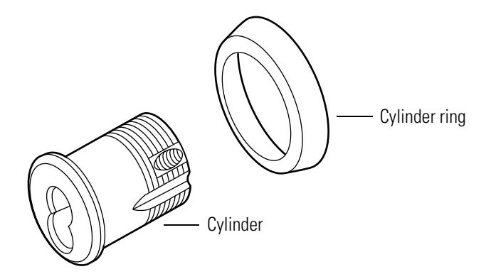
Figure 5.8 Reinstalling the cylinder ring (mortise cylinder shown)
3. For mortise cylinders , reinstall the cylinder assembly in the door and the faceplate on the lock case ( page 5–4) .
For rim cylinders , reinstall the cylinder assembly in the door (page 5–10) .
For cabinet cylinders , reinstall the cylinder assembly in the cabinet door ( page 5–14 ).
Replacing riveted cams
Before beginning this process, get the following parts:
- two new throw pins
- one new throw plug
- one new stamped head.
Note: For ordering information, see the parts tables starting on page 2–2 or refer to the BEST Catalog.
To the remove the cam:
- 1. Remove the lock case faceplate, core, and cylinder from the door (page 5–2) .
- 2. Remove the cylinder ring from the cylinder ( page 5–7) .
- 3. Place the cylinder face down on a flat cloth-covered surface to avoid scratching the front of the cylinder.
- 4. Position a standard 3/32″ punch at the center point of one of the two throw pins. See Figure 5.9.
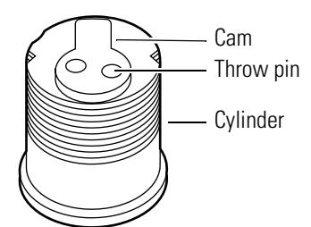
Figure 5.9 Removing the cam
- 5. Using a ballpeen hammer, hit the punch two or three times to drive the throw pin out of the cam.
- 6. Repeat steps 4 and 5 to remove the remaining throw pin. Discard the throw pins.
- 7. Remove the cam.
- 8. Discard the stamped head and throw plug.
To reinstall the cam:
- 1. If installing a new cam , use the cylinder cam testing tool (page 2–14) to make sure the cam will function properly when installed in the door.
-
2. Refer to Figure 5.10 and assemble the following parts onto the cam assembly tool:
- two throw pins
- throw plug
- stamped head
- cylinder.
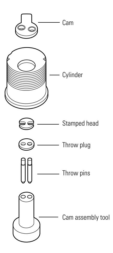
Figure 5.10 Reinstalling the cam
- 3. Position the cam on the back of the cylinder so that the throw pins go through the two cam holes.
- 4. Using a ballpeen hammer, hit around the edges of the two throw pins until the ends of the throw pins are level with the surface of the cam.
5. Remove the cam assembly tool.
Note: If the tool cannot be removed from the cylinder, hold the cylinder in one hand (with the cam in the palm of your hand) and strike the bottom of the cam assembly tool with the ballpeen hammer to loosen the cylinder.
- 6. Turn the cam clockwise and counterclockwise to make sure it is installed properly.
- 7. Reinstall the cylinder ring, if present onto the cylinder ( page 5–7) .
- 8. Reinstall the cylinder, the core, and the lock case faceplate on the door ( page 5–4) .
Replacing the rim cylinder
To remove the rim cylinder:
- 1. Remove the necessary trim components to expose the front and back of the rim cylinder. Contact your BEST Representative for more information.
- 2. On the inside of the door, remove the two mounting screws and the clamp plate. See Figure 5.11.
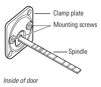
Figure 5.11 Removing the rim cylinder
- 3. Note the orientation of the spindle and slide the cylinder assembly out from the outside of the door.
- 4. Insert the control key into the core and rotate the key 15 degrees to the right. Remove the core.
To reinstall the rim cylinder:
- 1. Make sure that the cylinder ring, if present, is positioned on the cylinder, as shown in Figure 5.12.
- 2. Orient the cylinder assembly so that the throw pins are on the bottom of the figure-8 opening.
- 3. Make sure that the spindle is oriented in the position that you noted above.
Note: Depending on the application, spindles may be installed vertically and horizontally.
4. From the outside of the door, insert the rim cylinder assembly into the cylinder hole.
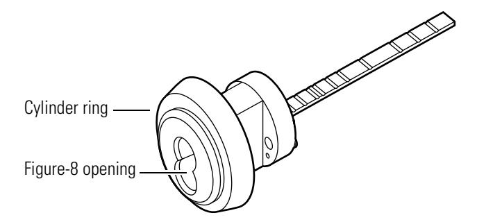
Figure 5.12 Figure-8 opening
-
5. If installing a new cylinder:
- a. Break off the new spindle to match the length of the old spindle.
- b. Break off the new mounting screws to match the length of the old mounting screws.
- 6. On the inside of the door, orient the cylinder and clamp plate as shown in Figure 5.13.
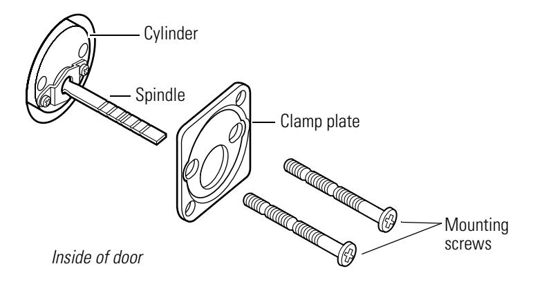
Figure 5.13 Reinstalling the rim cylinder
- 7. Secure the clamp plate to the cylinder with the mounting screws.
- 8. Insert the control key and core into the cylinder. Rotate the control key 15 degrees counterclockwise and then remove the key.
- 9. Reinstall the necessary trim components. Contact your BEST Representative for more information.
- 10. Lock and unlock the door to be sure the cylinder is installed properly.
Replacing the spindle
To remove the spindle:
- 1. Remove the cylinder from the door ( page 5–10) .
- 2. Note the orientation of the spindle (horizontal or vertical).
- 3. Using a narrow-blade screwdriver, unscrew the two retainer screws and remove the throw member retainer and spindle. See Figure 5.14.
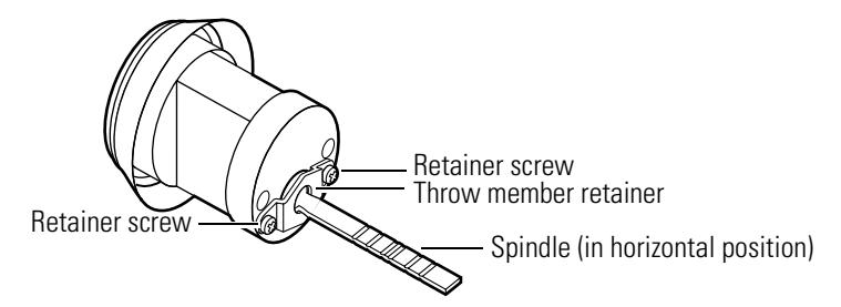
Figure 5.14 Removing the spindle
To reinstall the spindle:
- 1. Break off the new spindle to match the length of the old spindle.
- 2. Using the same orientation as the old spindle (horizontal or vertical), align the spindle so that it fits into the throw plug. See Figure 5.15.
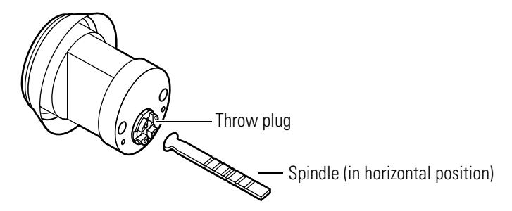
Figure 5.15 Reinstalling the spindle
3. While holding the spindle in place, use a narrow-blade screwdriver to secure the throw member retainer to the back of the cylinder with the two retainer screws. See Figure 5.16.
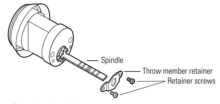
Figure 5.16 Securing the spindle
4. Reinstall the cylinder in the door (see page 5–10) .
Replacing cabinet cylinders
To remove the cabinet cylinder:
- 1. Using an operating key, open the cabinet to expose the back of the cylinder assembly.
- 2. Using a narrow-blade screwdriver, unscrew the two cam screws located on the back of the cylinder assembly. See Figure 5.17.
Note: The 1E7E4 cylinder has only one cam screw.
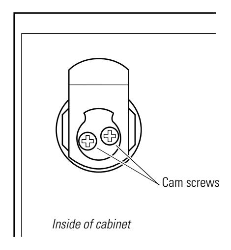
Figure 5.17 Location of cam screws (5E Series cylinder assembly shown)
-
3.
For the 1E7D4 cylinder
, remove the following parts (see
page 2–5
for part numbers and drawings):
- cam
- throw plug retainer.
For the 1E7E4 cylinder , remove the following parts (see page 2–6 for part numbers and drawings):
- washer
- cam driver
- cam with drive pin.
For 5E Series cylinders , remove the following parts, if present (see page 4–2 and page 4–3 for part numbers and drawings):
- two washers
- cam driver
- stop plate
- cam
- plug throw.
- 4. Unscrew the nut and remove it from the cylinder.
- 5. Remove the lock washer, if present.
- 6. Slide the cylinder assembly out from the front of the cabinet door.
To reinstall the cabinet cylinder:
- 1. Make sure that the cylinder ring is positioned on the cylinder.
- 2. Insert the cylinder into the front of the cabinet door.
- 3. While holding the front of the cylinder in place, attach the lock washer, if present, to the back end of the cylinder assembly so that it is flush with the cabinet door.
- 4. Thread the nut onto the cylinder and tighten it to secure the cylinder in the cabinet door.
-
5.
For the 1E7D4 cylinder
, reinstall the following parts (see
page 2–5
for part numbers and drawings):
- throw plug retainer
- cam in the locked position (see page 5–16 for 1E7D4 cam rotations).
For the 1E7E4 cylinder , reinstall the following parts (see page 2–6 for part numbers and drawings):
- cam in the locked position (see page 5–17 for 1E7E4 cam rotations).
- cam driver
- washer.
For 5E cylinders , reinstall the following parts, if present (see page 4–2 and page 4–3 for part numbers and drawings):
- plug throw
- cam in the locked position (see page 5–18 for 5E cam rotations).
- cam driver
- stop plate
- two washers.
6. Secure the two cam screws to the back of the cylinder assembly. See Figure 5.18.
Note: 1E7E4 cylinders have only one cam screw.
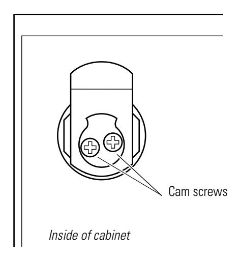
Figure 5.18 Reinstalling the cabinet cylinder (5E Series cylinder assembly shown)
7. Lock and unlock the cabinet to make sure the cylinder is installed properly.
CAM ROTATIONS FOR 1E SERIES CYLINDERS
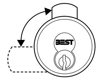
Direct motion cabinet cylinders
This section shows the cam rotation options for 1E7D4 direct motion cabinet cylinders.
Note: The following cam rotations only apply to cylinders with cores installed in the orientation shown.
For direct motion cylinders, the key and cam rotation is direct and both rotate 360°. The key can be removed in the locked position only. The figures below indicate the direction of the cam rotation and the locked position.
Note: See page 2–20 for common cabinet cams.
- For upward locking applications
- Cam locks in the 12 o'clock position
1E7D4 LH 12 1E7D4 RH 12
- For upward locking applications
- Cam locks in the 12 o'clock position
1E7D4 LH 6 1E7D4 RH 6
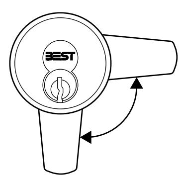
- For downward locking applications
- Cam locks in the 6 o'clock position
- For downward locking applications
- Cam locks in the 6 o'clock position
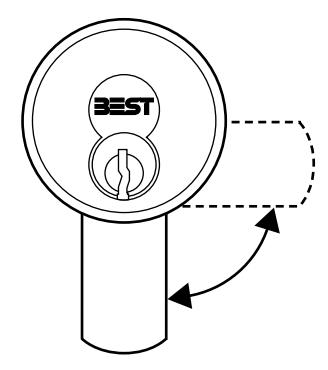
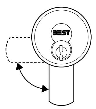
Lost motion cabinet cylinders
This section shows the cam rotation options for 1E7E4 lost motion cabinet cylinders.
Note: The following cam rotations only apply to cylinders with cores installed in the orientation shown.
For lost motion cylinders, the cam rotates 90° and the key rotates 360°. The key can be removed with the cam in the locked or unlocked position. The figures below indicate the direction and range of cam rotation, as well as the locked positions.
Note: See page 2–20 for common cabinet cam options.
1E7E4 LH 12 or 3 1E7E4 RH 12 or 9
- For upward locking applications
- Cam locks in the 12 o'clock or 3 o'clock position
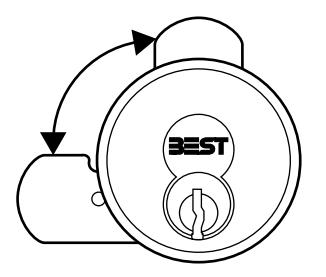
- For upward locking applications
- Cam locks in the 12 o'clock or 9 o'clock position
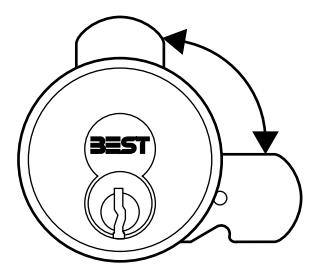
- For downward locking applications
- Cam locks in the 3 o'clock or 6 o'clock position
1E7E4 LH 3 or 6 1E7E4 RH 6 or 9
- For downward locking applications
- Cam locks in the 6 o'clock or 9 o'clock position
CAM ROTATIONS FOR 5E SERIES CYLINDERS
The following section contains cam rotation options for 5E Series 7-pin cylinders. 5E Series cylinders are categorized by cam motion type. The table below shows the cam motion types described in this section.
| Type | Motion | Height of groove pins are: | Cam rotation | Key rotation |
Key can be removed
when cam is in: |
|---|---|---|---|---|---|
| B | Limited |
Above the throw plug.
See Figure 5.19. |
90° or 180° | 90° or 180° | Locked position |
| C | Lost |
Level with the throw plug.
See Figure 5.20. |
90° | 360° | Locked or unlocked position |
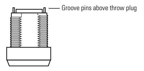
Figure 5.19 Groove pins installed for limited motion rotations
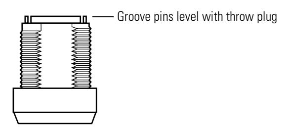
Figure 5.20 Groove pins installed for lost motion rotations
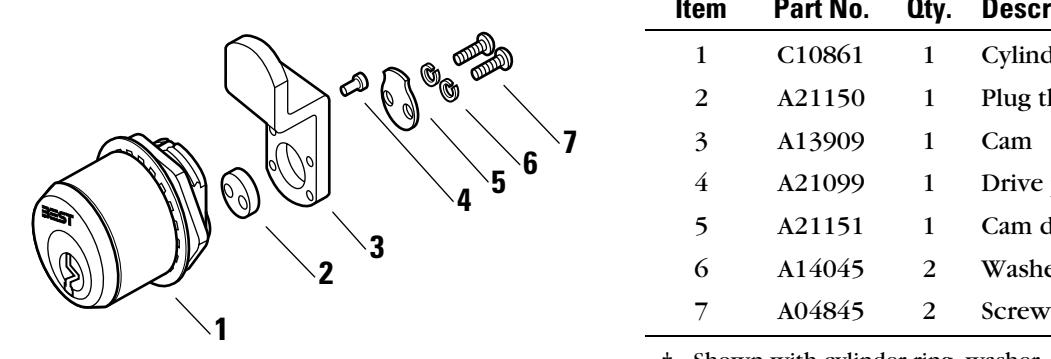
LOST MOTION C3 CAM ROTATION
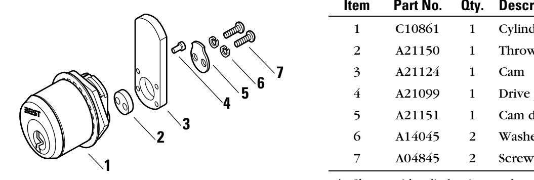
| Item | Part No. | Qty. | Description |
|---|---|---|---|
| 1 | C10861 | 1 | Cylinder and plug assembly† |
| 2 | A21150 | 1 | Throw plug |
| 3 | A21124 | 1 | Cam |
| 4 | A21099 | 1 | Drive pin |
| 5 | A21151 | 1 | Cam driver |
| 6 | A14045 | 2 | Washer |
† Shown with cylinder ring, washer, and nut.
Figure 5.21 5E Series lost motion C3 cam rotation
The C3 cam is a straight cam mounted for lost motion operation. The diagrams below show rotation assemblies for the C3 cam. The arrow in each diagram indicates where the drive pin should be inserted into the cam. When assembling the cylinder, orient the cam driver and cam in the position shown.
|
12†
R‡ 90†† |
3 R 90 | 6 R 90 | 9 R 90 |
|---|---|---|---|
|
Cam
Cam Cylinder and driver plug assembly Rear view |
|||
| 12 L 90 | 3 L 90 | 6 L 90 | 9 L 90 |
† Indicates the locked cam mounting position as seen from the front of the cylinder (for example, 12 = 12 o'clock position).
‡ Indicates the direction of cam rotation as seen from the front of the cylinder (L = left, R = right).
†† Indicates the degree of cam rotation (90 = 90°, 180 = 180°).
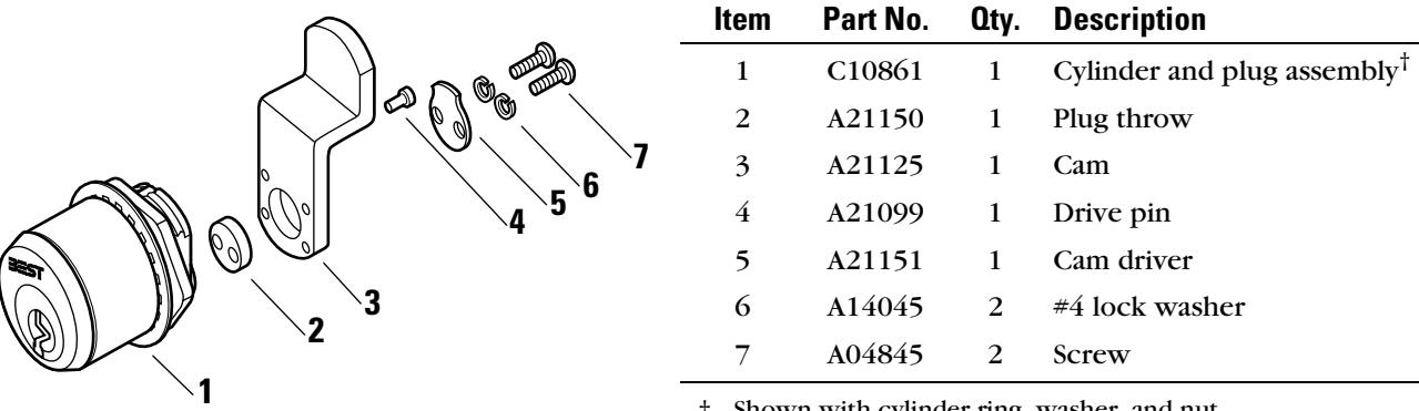
LOST MOTION C4A CAM ROTATION
| Item | Part No. | Qty. | Description |
|---|---|---|---|
| 1 | C10861 | 1 | Cylinder and plug assembly† |
| 2 | A21150 | 1 | Plug throw |
| 3 | A13909 | 1 | Cam |
| 4 | A21099 | 1 | Drive pin |
| 5 | A21151 | 1 | Cam driver |
| 6 | A14045 | 2 | Washer |
† Shown with cylinder ring, washer, and nut.
Figure 5.22 5E Series lost motion 4A cam rotation
The 4A cam is an offset cam (inward mount) for lost motion operation. The diagrams below show rotation assemblies for the 4A cam. The arrow in each diagram indicates where the drive pin should be inserted into the cam. When assembling the cylinder, orient the cam driver and cam in the position shown.
|
12†
R‡ 90†† |
3 R 90 | 6 R 90 | 9 R 90 |
|---|---|---|---|
|
Cam
Cam Cylinder and driver plug assembly Rear view |
|||
| 12 L 90 | 3 L 90 | 6 L 90 | 9 L 90 |
† Indicates the locked cam mounting position as seen from the front of the cylinder (for example, 12 = 12 o'clock position).
‡ Indicates the direction of cam rotation as seen from the front of the cylinder (L = left, R = right).
†† Indicates the degree of cam rotation (90 = 90°, 180 = 180°).
LOST MOTION C4B CAM ROTATION
† Shown with cylinder ring, washer, and nut.
Figure 5.23 5E Series lost motion 4B cam rotation
The 4B cam is an offset cam (outward mount) for lost motion operation. The diagrams below show rotation assemblies for the 4B cam. The arrow in each diagram indicates where the drive pin should be inserted into the cam. When assembling the cylinder, orient the cam driver and cam in the position shown.
|
12†
R‡ 90†† |
3 R 90 | 6 R 90 | 9 R 90 |
|---|---|---|---|
|
Cam
Cam Cylinder and driver plug assembly Rear view |
|||
| 12 L 90 | 3 L 90 | 6 L 90 | 9 L 90 |
† Indicates the locked cam mounting position as seen from the front of the cylinder (for example, 12 = 12 o'clock position).
‡ Indicates the direction of cam rotation as seen from the front of the cylinder (L = left, R = right).
†† Indicates the degree of cam rotation (90 = 90°, 180 = 180°).
LIMITED MOTION C1 CAM ROTATION
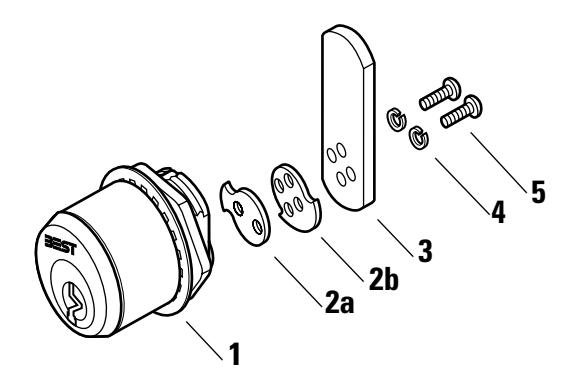
| Item | Part No. | Qty. | Description |
|---|---|---|---|
| 1 | C10861 | 1 | Cylinder and plug assembly† |
| 2a | A21302 | 1 | 180° rotation stop plate |
| 2b | A14065 | 1 | 90° rotation stop plate |
| 3 | A10281 | 1 | Cam |
| 4 | A09930 | 2 | Washer |
| 5 | A09929 | 2 | Screw |
† Shown with cylinder ring, washer, and nut.
Figure 5.24 5E Series limited motion C1 cam rotation
The C1 cam is a straight cam mounted for fixed motion operation. The diagrams below show rotation assemblies for the C1 cam. Use the diagrams below to determine the orientation of the stop plate and cam.
|
12†
R‡ 90†† |
3 R 90 | 6 R 90 | 9 R 90 | |
|---|---|---|---|---|
|
Stop
plate |
Cam
Cylinder and plug assembly Rear view |
|||
| 12 R 180 | 3 R 180 | 6 R 180 | 9 R 180 | |
|
Stop
plate |
||||
| 12 L 90 | 3 L 90 | 6 L 90 | 9 L 90 | |
| 12 L 180 | 3 L 180 | 6 L 180 | 9 L 180 | |
† Indicates the locked cam mounting position as seen from the front of the cylinder (for example, 12 = 12 o'clock position).
5–22 E Series Service Manual
‡ Indicates the direction of cam rotation as seen from the front of the cylinder (L = left, R = right).
†† Indicates the degree of cam rotation (90 = 90°, 180 = 180°).
LIMITED MOTION C2A CAM ROTATION
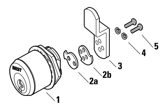
| Item | Part No. | Qty. | Description |
|---|---|---|---|
| 1 | C10861 | 1 | Cylinder and plug assembly† |
| 2a | A21302 | 1 | 180° rotation stop plate |
| 2b | A14065 | 1 | 90° rotation stop plate |
| 3 | A14050 | 1 | Cam |
| 4 | A09930 | 2 | Washer |
| 5 | A09929 | 2 | Screw |
† Shown with cylinder ring, washer, and nut.
Figure 5.25 5E Series limited motion C2A cam rotation
The C2A cam is an offset cam (inward mount) for fixed motion operation. The diagrams below show rotation assemblies for the 2A cam. Use the diagrams below to determine the orientation of the stop plate and cam.
|
12†
R‡ 90†† |
3 R 90 | 6 R 90 | 9 R 90 | |
|---|---|---|---|---|
|
Stop
plate |
Cam
Cylinder and plug assembly Rear view |
|||
| 12 R 180 | 3 R 180 | 6 R 180 | 9 R 180 | |
|
Stop
plate |
||||
| 12 L 90 | 3 L 90 | 6 L 90 | 9 L 90 | |
| 12 L 180 | 3 L 180 | 6 L 180 | 9 L 180 | |
† Indicates the locked cam mounting position as seen from the front of the cylinder (for example, 12 = 12 o'clock position).
‡ Indicates the direction of cam rotation as seen from the front of the cylinder (L = left, R = right).
†† Indicates the degree of cam rotation (90 = 90°, 180 = 180°).
LIMITED MOTION C2B CAM ROTATION
| Item | Part No. | Qty. | Description |
|---|---|---|---|
| 1 | C10861 | 1 | Cylinder and plug assembly† |
| 2a | A21302 | 1 | 180° rotation stop plate |
| 2b | A14065 | 1 | 90° rotation stop plate |
| 3 | A14051 | 1 | Cam |
| 4 | A09930 | 2 | Washer |
| 5 | A09929 | 2 | Screw |
† Shown with cylinder ring, washer, and nut.
Figure 5.26 5E Series limited motion C2B cam rotation
The C2B cam is an offset cam (outward mount) for fixed motion operation. The diagrams below show rotation assemblies for the 2B cam. Use the diagrams below to determine the orientation of the stop plate and cam.
|
12†
R‡ 90†† |
3 R 90 | 6 R 90 | 9 R 90 | |
|---|---|---|---|---|
|
Stop
plate |
Cam
Cylinder and plug assembly Rear view |
|||
| 12 R 180 | 3 R 180 | 6 R 180 | 9 R 180 | |
|
Stop
plate |
||||
| 12 L 90 | 3 L 90 | 6 L 90 | 9 L 90 | |
| 12 L 180 | 3 L 180 | 6 L 180 | 9 L 180 | |
† Indicates the locked cam mounting position as seen from the front of the cylinder (for example, 12 = 12 o'clock position).
‡ Indicates the direction of cam rotation as seen from the front of the cylinder (L = left, R = right).
†† Indicates the degree of cam rotation (90 = 90°, 180 = 180°).
TROUBLESHOOTING
The table summarizes the possible causes for certain cylinder problems. The causes of failure are listed in the order of likelihood. (The most like cause is first, and so forth.)
For problems with the core and key, such as difficulty removing or inserting the key or difficulty turning the key, see the Core and Key Service Manual [T35527].
For problems with the BEST mortise lock case, see the H Series Service Manual [T61964].
| You notice | Possible causes include | You should |
|---|---|---|
|
Cannot remove the core from the
cylinder. |
Set screw is installed with the
slotted head toward the outside of the cylinder, securing the core in the cylinder. |
Remove the mortise case faceplate
(pg. 5-2). Using a narrow-bladed screwdriver, loosen the set screw so that the core can be removed from the cylinder. |
|
Note: To use the set screw to secure
the cylinder to the mortise case, reverse the position of the set screw in the cylinder (pg. 5-4). |
||
|
Cannot insert the core into the
cylinder. |
a. Set screw is installed too far
down in the cylinder. |
a. Remove the mortise case
faceplate (pg. 5-2) and use a screwdriver to adjust the position of the set screw (pg. 5-4). |
|
b. Throw pins are not horizontally
aligned. |
b. Adjust the two throw pins so they
are aligned with the two core holes. |
|
|
c. A 7-pin core is being inserted into
a 7-pin cylinder that has a 6-pin spacer installed. |
c. Remove the spacer from the
cylinder. |
|
| Cannot turn key easily in the core. |
a. Cam is riveted too tightly onto
the cylinder. |
a. Place the cylinder on the cam
assembly tool and strike the cam once or twice with a ballpeen hammer to loosen it. Repeat if necessary. |
|
b. Cylinder ring is too deep or too
shallow for the cylinder being used. |
b. Replace the old ring with a ring
of appropriate size. |
|
|
c. Wrong cam is being used for the
lock application. |
c. Replace the old cam with the cam
appropriate for the lock application. |
5–26 E Series Service Manual

A E SERIES CAMS TABLE
The following table lists E Series cams according to their part numbers.
Note: Cylinders 2 inches or longer require a thumbturn cam.
E SERIES CAMS
| Part no. | Cam | Series | Description |
|---|---|---|---|
| A00117 | C101 | 1E | Straight |
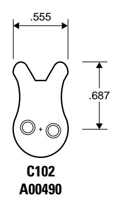
| A00490 | C102 | 1E | Two-point |
| A00533 | C103 | 1E | Straight |
| A00683 | C110 | 1E | Straight |
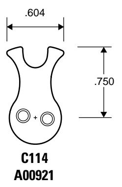
| A00921 | C114 | 1E | Two-point |
| A00967 | C115 | 1E | Straight |
| A00995 | C118 | 1E, 3E | Cloverleaf |
| A01172 | C121 | 1E | Straight |
| A01225 | C123 | 1E | Straight |
| A01231 | C124 | 1E | Straight |
| A01247 | C127 | 1E, 3E | Straight |
| A01248 | C128 | 1E | Straight |
| A01249 | C129 | 1E | Straight |
| A01400 | C130 | 1E | Straight |
| A01401 | C131 | 1E | Straight |
| A01414 | C134 | 1E | Straight |
| A01416 | C136 | 1E, 3E | Straight |
| A01417 | C137 | 1E | Straight |
| A01449 | C140 | 1E | Thumbturn |
| A01475 | C142 | 1E | Roller |
| A01487 | C143 | 1E | Straight |
| A01707 | C148 | 1E | Straight |
| A01799 | C152 | 1E | Straight |
| A02532 | C253 | 1E | Cabinet |
| A02534 | C235 | 1E | Cabinet |
| A02770 | C161 | 1E, 3E | Cloverleaf |
| A04284 | C221 | 1E | Roller |
| A04387 | C162 | 1E | Straight |
| A04399 | C165 | 1E | Straight |
| A04445 | C169 | 1E | Straight |
| Part no. | Cam | Series | Description |
|---|---|---|---|
| A04492 | C171 | 1E | Straight |
| A04533 | NA | 1E, 3E | Roller |
| A04607 | NA | 1E | Cabinet |
| A04737 | C254 | 1E | Cloverleaf |
| A05397 | C177 | 1E | Straight |
| A05466 | C178 | 1E | Straight |
| A05979 | C181 | 1E | Straight |
| A05989 | C182 | 1E | Straight |
| A06060 | C185 | 1E | Straight |
| A06190 | C186 | 1E | Straight |
| A06246 | C187 | 1E | Straight |
| A06419 | C191 | 1E | Straight |
| A06421 | C238 | 1E | Cabinet |
| A07190 | C193 | 1E | Straight |
| A07212 | C239 | 1E | Straight |
| A07221 | C240 | 1E | Roller |
| A07543 | C199 | 1E | Cabinet |
| A07605 | C200 | 1E | Straight |
| A07747 | C203 | 1E | Straight |
| A07880 | C204 | 1E | Cloverleaf |
| A07990 | C229 | 1E | Cabinet |
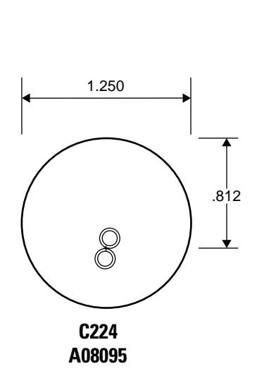
| A08095 | C224 | 1E | Cabinet |
| A08778 | C228 | 1E | Cabinet |
| A08854 | NA | 1E | Cabinet |
| A09225 | C241 | 1E | Cabinet |
| A09229 | C223 | 1E | Straight |
| A09230 | C243 | 1E | Cloverleaf |
| A09359 | C233 | 1E | Straight |
| A09419 | C245 | 5E | Cabinet |
| A09881 | C246 | 1E | Cabinet |
| A10281 | NA | 5E | Cabinet |
| A10500 | C401 | 1E | Thumbturn |
| Part no. | Cam | Series | Description |
|---|---|---|---|
| A10501 | C402 | 1E | Thumbturn |
| A10502 | C403 | 1E | Thumbturn |
| A10503 | C404 | 1E | Thumbturn |
| A10504 | C405 | 1E | Thumbturn |
| A10505 | C406 | 1E | Thumbturn |
| A10506 | C407 | 1E | Thumbturn |
| A10507 | C408 | 1E | Thumbturn |
| A10508 | C409 | 1E | Thumbturn |
| A10509 | C410 | 1E | Thumbturn |
| A10510 | C411 | 1E | Thumbturn |
| A10511 | C412 | 1E | Thumbturn |
| A10512 | C413 | 1E | Thumbturn |
| A10513 | C414 | 1E | Thumbturn |
| A10514 | C415 | 1E | Thumbturn |
| A10515 | C416 | 1E | Thumbturn |
| A10516 | C417 | 1E | Thumbturn |
| A10517 | C418 | 1E | Thumbturn |
| A10518 | C419 | 1E | Thumbturn |
| A10519 | C420 | 1E | Thumbturn |
| A10520 | C421 | 1E | Thumbturn |
| A10521 | C422 | 1E | Thumbturn |
| A10522 | C423 | 1E | Thumbturn |
| A10523 | C424 | 1E | Thumbturn |
| A10524 | C425 | 1E | Thumbturn |
| A10525 | C426 | 1E | Thumbturn |
| A10526 | C427 | 1E | Thumbturn |
| A10527 | C428 | 1E | Thumbturn |
| A10528 | C429 | 1E | Thumbturn |
| A10529 | C430 | 1E | Thumbturn |
| A10530 | C431 | 1E | Thumbturn |
| A10531 | C432 | 1E | Thumbturn |
| A10532 | C433 | 1E | Thumbturn |
| Part no. | Cam | Series | Description |
|---|---|---|---|
| A10533 | C434 | 1E | Thumbturn |
| A10534 | C435 | 1E | Thumbturn |
| A10535 | C436 | 1E | Thumbturn |
| A10536 | C437 | 1E | Thumbturn |
| A10537 | C438 | 1E | Thumbturn |
| A10538 | C439 | 1E | Thumbturn |
| A10539 | C440 | 1E | Thumbturn |
| A10540 | C441 | 1E | Thumbturn |
| A10541 | C442 | 1E | Thumbturn |
| A10542 | C443 | 1E | Thumbturn |
| A10543 | C444 | 1E | Thumbturn |
| A10544 | C445 | 1E | Thumbturn |
| A10545 | C446 | 1E | Thumbturn |
| A10546 | C447 | 1E | Thumbturn |
| A10547 | C448 | 1E | Thumbturn |
| A10548 | C449 | 1E | Thumbturn |
| A10549 | C450 | 1E | Thumbturn |
| A13909 | C4A | 5E | Cabinet |
| A14050 | C2A | 5E | Cabinet |
| A14051 | C2B | 5E | Cabinet |
| A14154 | NA | 1E | Cabinet |
| A14333 | C220 | 1E | Straight |
| A14472 | C210 | 1E, 3E | Straight |
| A14520 | C208 | 1E, 3E | Straight |
| A14521 | C209 | 1E | Straight |
| A15981 | C211 | 1E | Straight |
| A17744 | C226 | 1E | Straight |
| A19851 | C247 | 1E | Straight |
| A20010 | C248 | 1E | Cabinet |
| A20023 | C249 | 1E | Cabinet |
| A20069 | C250 | 1E | Cabinet |
| A20128 | C227 | 1E | Roller |
| Part no. | Cam | Series | Description |
|---|---|---|---|
| A20332 | C251 | 1E | Roller |
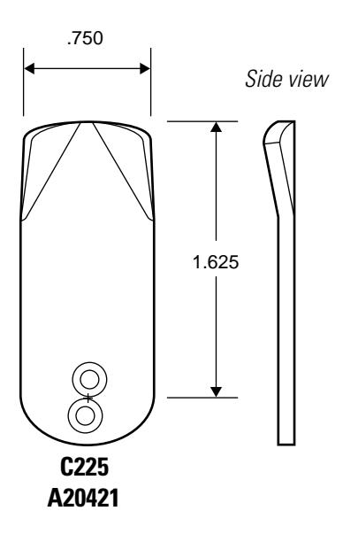
| A20421 | C225 | 1E | Cabinet |
| A20474 | C252 | 1E | Straight |
| A20877 | C222 | 1E | Cloverleaf |
| A20931 | C231 | 1E | Straight |
| A20942 | C242 | 1E | Straight |
| A21124 | C3 | 5E | Cabinet |
| A21125 | 4B | 5E | Cabinet |
| A21198 | NA | 5E | Cabinet |
| A23770 | C256 | 1E | Cloverleaf |
| A26344 | NA | 5E | Cabinet |
| A40088 | C234 | 1E | Straight |
| A40091 | C4 | 1E, 3E | Straight |
| A40092 | C3 | 3E | Straight |
| A63060 | C500 | 1E | Cabinet |
| A63061 | C501 | 1E | Cabinet |
| A63062 | C502 | 1E | Cabinet |
| A63063 | C503 | 1E | Cabinet |
| A63064 | C504 | 1E | Cabinet |
| A63065 | C505 | 1E | Cabinet |
| A63066 | C506 | 1E | Cabinet |
| A63067 | C507 | 1E | Cabinet |
| A63068 | C508 | 1E | Cabinet |
| A63069 | C509 | 1E | Cabinet |
| B04796 | C173 | 1E | Straight |
| B05467 | C179 | 1E | Straight |
| B34077 | C258 | 1E | Cloverleaf |
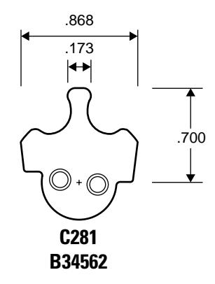
| B34562 | C281 | 1E | Cloverleaf |
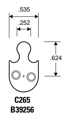
| B39256 | C265 | 1E | Cloverleaf |
B THUMBTURN CAM CONVERSION TABLE
The following pages list standard cams with part numbers and their equivalent counter-sunk thumbturn cams with part numbers.
Note: Cylinders 2 inches or longer require a thumbturn cam.
THUMBTURN CAM CONVERSION TABLE
The following table lists standard cams with part numbers and their equivalent counter-sunk thumbturn cams with part numbers. Figure 2.1 shows a standard cam and its equivalent thumbturn cam.
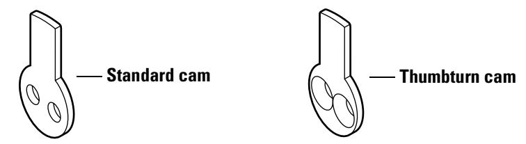
Figure 2.1 C4 standard cam and equivalent C140 thumbturn cam
| Standard | Thumbturn | ||
|---|---|---|---|
| Cam | Part no. | Cam | Part no. |
| C4 | A40091 | C140 | A01449 |
| C101 | A00117 | C425 | A10524 |
| C103 | A00533 | C447 | A10546 |
| C115 | A00967 | C444 | A10543 |
| C118 | A00995 | C401 | A10500 |
| C121 | A01172 | C402 | A10501 |
| C123 | A01225 | C443 | A10542 |
| C127 | A01247 | C403 | A10502 |
| C128 | A01248 | C404 | A10503 |
| C129 | A01249 | C405 | A10504 |
| C134 | A01414 | C406 | A10505 |
| C136 | A01416 | C432 | A10531 |
| C137 | A01417 | C442 | A10541 |
| C142 | A01513 | C426 | A10525 |
| C143 | A01487 | C407 | A10506 |
| C151 | A01798 | C434 | A10533 |
| C161 | A02770 | C408 | A10507 |
| C162 | A04387 | C409 | A10508 |
| C164 | A04398 | C430 | A10529 |
| C165 | A04399 | C424 | A10523 |
| C169 | A04445 | C410 | A10509 |
| Standard | Thumbturn | ||
|---|---|---|---|
| Cam | Part no. | Cam | Part no. |
| C171 | A04492 | C423 | A10522 |
| C173 | B04796 | C411 | A10510 |
| C178 | A05466 | C433 | A10532 |
| C179 | B05467 | C412 | A10511 |
| C181 | A05979 | C413 | A10512 |
| C186 | A06190 | C414 | A10513 |
| C191 | A06419 | C428 | A10527 |
| C193 | A07190 | C429 | A10528 |
| C200 | A07605 | C436 | A10535 |
| C201 | A07698 | C445 | A10544 |
| C203 | A07747 | C441 | A10540 |
| C208 | A14520 | C417 | A10516 |
| C209 | A14521 | C418 | A10517 |
| C210 | A14472 | C416 | A10515 |
| C211 | A15981 | C419 | A10518 |
| C222 | A17744 | C420 | A10519 |
| C226 | A17744 | C422 | A10521 |
| C231 | A20931 | C421 | A10520 |
| C241 | A09229 | C415 | A10514 |
| C244 | A20511 | C446 | A10545 |
| C258 | B34077 | C427 | A10526 |
| C265 | B39256 | C431 | A10530 |
| C273 | A24039 | C437 | A10536 |
| C277 | A34312 | C439 | A10538 |
| C278 | A34313 | C438 | A10537 |
| C279 | A20701 | C440 | A10539 |
| C281 | B34562 | C448 | A10547 |
| NA | A09404 | C435 | A10534 |
| NA | A20010 | C449 | A10548 |
| NA | A23770 | C450 | A10549 |
B-4 E Series Service Manual
C GLOSSARY
Cam Part of the cylinder that rotates to actuate the
deadbolt or latchbolt as the key is turned. The cam
may also act as the bolt in a utility cam lock.
Cam assembly tool Tool used for assembling the cam to the mortise
cylinder.
Clamp plate Metal plate on the inside of a door used to secure a
rim lock cylinder to the door by means of clamp screws. The spindle of the cylinder extends through
a hole in the clamp plate.
Core Interchangeable figure-8 device that can be installed
in a lock or door and operated by a key.
Cylinder Subassembly of a lock containing a plug with keyway
and a body with tumbled mechanism. Cylinders may have either a cam (See Mortise cylinder ) or a spindle
(see Rim cylinder ) as the actuator.
Cylinder die Tool for rethreading a 1 5/32″ diameter cylinder.
Cylinder lock Lock in which the locking mechanism is controlled
by a cylinder. A double-cylinder lock has a cylinder
on both the inside and outside of the door.
Cylinder ring Metal ring, surrounding the exposed portion of a
lock cylinder, which protects the cylinder from being wrenched, turned, pried, cut, or pulled with
attack tools. The cylinder ring also adapts the
cylinder to the door thickness.
Cylinder tap Tool for rethreading lock case threads.
Cylinder wrench Tool for installing, removing, and testing cylinders.
Dummy cylinder Nonfunctional cylinder without an operating mechanism used for
appearance only. Dummy cylinders are available for mortise and rim
locks.
Faceplate Part of the mortise lock that serves as a facing or covering over the front
of the lock.
Hand-of-door Opening direction of the door. A right-hand door (RH) is called "right-
hand" because it is opened with the right hand. A right-hand door is hinged on the right and swings inward when viewed from the outside. A left-handed door (LH) is hinged on the left and swings inward when viewed from the outside. If a door swings outward, it is referred to as a right hand reverse bevel door (RHRB) or a left-hand reverse bevel door
(LHRB).
Latchbolt Beveled, spring-actuated, bolt which may or may not include a
deadlocking feature. The latchbolt must be actuated by a key, knob, or
turn knob.
Lock Device that secures openings and entrances such as doors, gates,
cabinets, and so forth. Locks include mechanical, electromechanical,
and electronic security devices.
Mortise Rectangular cavity cut into the edge of a door. Mortise also can mean
the act of making such a cavity.
Mortise cylinder Threaded lock cylinder that screws directly into the lock case; usually
includes a key-driven rotating cam, attached to the back of the cylinder, which drives the locking mechanism. The cylinder houses the BEST
interchangeable core.
Mortise lock Lock that fits into a mortise. Other locks fit into bored holes or mount
to a surface.
Rim cylinder Lock cylinder that is secured to a door with a clamp plate and clamp
screws. The rim cylinder's spindle actuates the bolt or latch. The
cylinder houses the BEST interchangeable core.
Shifting cam Spring-loaded cam that shifts back to actuate another mechanism.
Spindle Unit on a rim cylinder lock, which actuates the bolt or latch when the
key is turned.
Throw member Connecting piece between core and lock mechanism that transfers key
motion to the locking device.
Thumbturn Part that someone grips between the thumb and forefinger, and turns to
project or retract a bolt.
D INSTALLATION INSTRUCTIONS
The following pages contain Installation Instructions for 1E Mortise Cylinders and Installation Instructions for 1E Rim Cylinders.
D–2 E Series Service Manual

Installation Instructions for 1E Mortise Cylinders
Use these instructions to install a BEST 1E mortise cylinder in either a BEST mortise lock or another manufacturer's mortise lock.
Caution: Other lock manufacturers may make changes to their product that affect the operation or compatibility of the BEST cylinder. When this occurs, they are not obligated to notify us.
If you are using a BEST cylinder in another manufacturer's lock and find that it does not operate properly, please contact your local BEST representative.
1 Install cylinder set screw
- 1 From the outside of the cylinder, thread the set screw, slotted head first, as shown in Figure 1. .
- 2 With a narrow screwdriver, insert the blade through the figure-8 hole and back the set screw in until the tip of the screw is below the threads of the cylinder.
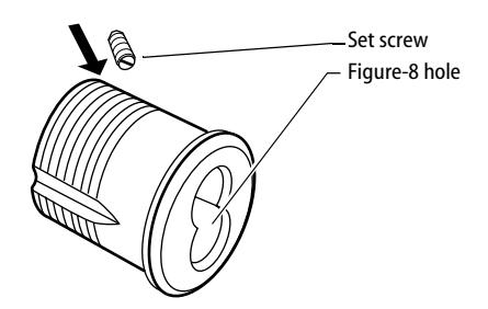
Figure 1 Threading the set screw into the cylinder
2 Install cylinder
- 1 Loosen the cylinder clamp screw in the front edge of the mortise lock and remove the old cylinder. See Figure 2 .
- 2 Note the length "L" of the old cylinder. Se e Figure 3 . If the BEST cylinder is longer, select a cylinder ring that will provide the correct length.
T61781/Rev – 1833073 ER7991-25 T61782/Rev – 1832242 ER7991-20 Mar 2001
BEST ACCESS SYSTEMS
Indianapolis, Indiana
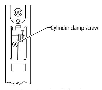
Figure 2 Loosening the cylinder clamp screw
- 3 Turn the cam to the 12 o'clock position as shown in Figure 3.
- 4 With a BEST cylinder wrench, screw the cylinder into the mortise case so that the figure-8 hole stops in the 12 o'clock position and the set screw is to the right.
Caution: Do not screw the cylinder in too tightly. Doing so may cause you or someone else to be locked out.
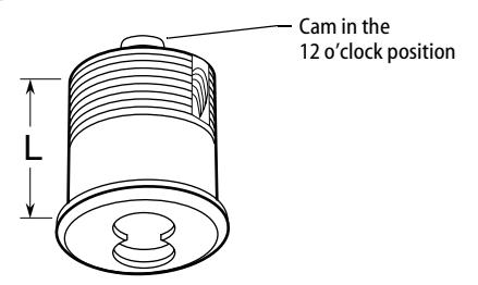
Figure 3 Turning the cam to the 12 o'clock position
- 5 Tighten the set screw into the mortise case. This prevents a thief from removing the cylinder and figure-8 core.
- 6 Tighten the cylinder clamp screw as shown in Figure 2.
3 Install core
- 1 Put the control key into the core and turn the key 15 degrees clockwise.
- 2 Adjust the throw pins if needed, then put the core into the cylinder with the control key.
- 3 Turn the key 15 degrees counterclockwise and remove the key.
BEST ACCESS SYSTEMS
Indianapolis, Indiana

Installation Instructions for 1E Rim Cylinders
Use these instructions to install a BEST 1E rim cylinder in rim lock applications.
Only if you are replacing a cylinder:
- 1 Remove the lock case (examples of lock cases include rim locks and panic devices) from the inside of the door and remove the cylinder.
- 2 Measure and make note of the length of the old ring, spindle, and screws. See Figure 1.
1 Prepare cylinder
Perform the following steps by either: (a) comparing the new BEST rings, spindle, and screws to the existing ring, spindle, and screws, or (b) trying and measuring the new BEST cylinder in the door with the lock case.
- 1 Select the cylinder ring that will position the cylinder to the correct length.
- 2 Break off the spindle at the point that will position it to the correct length.
3 Break off the screws so that the clamp plate and cylinder will tighten onto the door.
2 Install cylinder
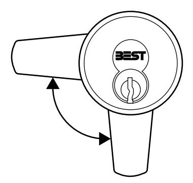
1 Insert the BEST cylinder from the outside of the door and secure it in place with the clamp plate. See Figure 1.
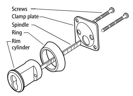
Figure 1 Securing the rim cylinder
Note: Make sure that the cylinder stays in the upright, centered position and that the spindle stays in the spindle hole in the lock case.
- 2 Reinstall the lock case.
- 3 Check the installation by inserting the key and turning. The key will operate the bolt freely if the cylinder and case are in proper alignment.
3 Install core
1 Put the control key into the core and turn the key 15 degrees clockwise. See Figure 2.
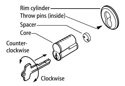
Figure 2 Installing the spacer (six-pin cores only) and core
- 2 When installing a six-pin core, slide the spacer onto the throw pins.
- 3 Adjust the throw pins if needed, then put the core into the cylinder with the control key.
- 4 Turn the key 15 degrees counterclockwise and remove the key.
BEST ACCESS SYSTEMS
E INDEX
| Numerics | 5E lost motion cabinet cylinder | |
|---|---|---|
| 1E direct motion cabinet cylinder | cam rotations 5–18 | |
| cam rotations 5–16 | part numbers and drawings for 4–2 | |
| part numbers and drawings for 2–5 | reinstalling 5–14 | |
| reinstalling 5–14 | removing 5–13 | |
| removing 5–13 | ||
| C | ||
| 1E dust cover cylinder 2–7 | ||
| 1E lost motion cabinet cylinder | cam driver 2–6, 4–2 | |
| cam rotations 5–17 | cam rotations | |
| part numbers and drawings for 2–6 | for 1E Series 5–16 | |
| reinstalling 5–14 | for 5E limited motion cabinet cylinders | |
| removing 5–13 | 5–22 | |
| 1E mortise cylinder | for 5E lost motion cabinet cylinders | |
| part numbers and drawings for 2–2 | 5–18 | |
| reinstalling 5–4 | cam stop pin 2–6 | |
| removing 5–2 | cams for 1E series | |
| 1E non-UL high security cylinder 2–8 | cabinet cams 2–20 | |
| 1E rim cylinder | cloverleaf cams 2–19 | |
| part numbers and drawings for 2–3 | reinstalling 5–9 | |
| reinstalling 5–10 | removing 5–8 | |
| removing 5–10 | roller cams 2–23 | |
| 1E tapered-head cylinder 2–8 | straight cams 2–15 | |
| 1E thumbturn cylinder 2–4 | two-point cams 2–24 | |
| 1E wrench-resistant cylinder 2–7 | cams for 3E Series | |
| 3E mortise cylinder | cloverleaf cams 3–4 | |
| part numbers and drawings for 3–2 | roller cams 3–5 | |
| reinstalling 5–4 | straight cams 3–4 | |
| removing 5–2 | cams for 5E series 4–7 | |
| 5E limited motion cabinet cylinder | certifications and standards 1–2 | |
| cam rotations 5–22 | clamp plate 2–3 | |
| part numbers and drawings for 4–3 | cylinder 2–2 to 2–6, 3–2 | |
| reinstalling 5–14 | cylinder and plug assembly 4–2 to 4–3 | |
| removing 5–13 | ||
| cylinder rings for 1E Series | P | removing |
|---|---|---|
| part numbers and drawings for | part numbers and drawings | 1E cylinder ring 5–7 |
| 2–10 | for 1E cams 2–15 | 1E direct motion cabinet |
| reinstalling 5–7 | for 1E cylinder rings 2–10 | cylinder 5–13 |
| removing 5–7 | for 1E direct motion cabinet | 1E lost motion cabinet cylinder |
| cylinder rings for 3E Series | cylinder 2–5 | 5–13 |
| part numbers and drawings for | for 1E dust cover cylinder 2–7 | 1E mortise cylinder 5–2 |
| 3–3 | for 1E hotel cylinder 2–8 | 1E rim cylinder 5–10 |
| reinstalling 5–7 | for 1E lost motion cabinet | 1E riveted cam 5–8 |
| removing 5–7 | cylinder 2–6 | 3E cylinder ring 5–7 |
| cylinder rings for 5E Series | for 1E mortise cylinder 2–2 | 3E mortise cylinder 5–2 |
| determining the ring length 4–4 | for 1E mounting plates 2–13 | 5E limited motion cabinet |
| part numbers and drawings for | for 1E non-UL high security | cylinder 5–13 |
| 4–5 | cylinder 2–8 | 5E lost motion cabinet cylinder |
| for 1E rim cylinder 2–3 | 5–13 | |
| D | for 1E tapered-head cylinder | spindle 5–12 |
| documentation package | 2–8 | rim cylinder |
| see technical documentation | for 1E thumbturn cylinder 2–4 | see 1E rim cylinder |
| package | for 1E wrench-resistant cylinder | rings |
| drawings | 2–7 | see cylinder rings |
| see part numbers and drawings | for 3E cams 3–4 | |
| drive pin 4–2 | for 3E cylinder rings 3–3 | S |
| dummy trim | for 3E mortise cylinder 3–2 | set screw 2–2, 3–2 |
| for 1E mortise cylinders 2–9 | for 5E cams 4–7 | slide cap 4–2 to 4–3 |
| for 1E rim cylinders 2–9 | for 5E cylinder rings 4–5 | spacer 2–2 to 2–3, 2–5 to 2–6, 3–2 |
| for 5E limited motion cabinet | spindle | |
| E | cylinder 4–3 | part numbers and drawings for |
| exploded diagrams | for 5E lost motion cabinet | 2–3 |
| see part numbers and drawings | cylinder 4–2 | reinstalling 5–12 |
| for 5E mounting plates 4–6 | removing 5–12 | |
| G | spring 2–4 | |
| R | spring plug 2–4 | |
| groove pin 4–2 to 4–3 | reinstalling | stamped head 2–2, 3–2 |
| 1E cylinder ring 5–7 | stop plate 4–3 | |
| H | 1E direct motion cabinet | support, technical |
| hotel shifting cam cylinder, 1E 2–8 | cylinder 5–14 | see technical support |
| 1E lost motion cabinet cylinder | ||
| L | 5–14 | T |
| lock washer 4–2 to 4–3 |
1E mortise cylinder 5–4
1E rim cylinder 5–10 |
technical documentation package
1–3 |
| 1E riveted cam 5–9 | technical support 1–3 | |
| M | 3E cylinder ring 5–7 | throw member assembly 2–6 |
| mounting plates | 3E mortise cylinder 5–4 | throw member retainer 2–3 |
| for 1E series 2–13 | 5E limited motion cabinet | throw pin 2–2, 2–5, 3–2 |
| for 5E series 4–6 | cylinder 5–14 | throw plug 2–2, 2–5, 3–2, 4–2 |
| 5E lost motion cabinet cylinder | throw plug assembly 2–3 | |
| N | 5–14 | throw plug retainer 2–5 |
| nut 2–5 to 2–6, 4–2 to 4–3 | spindle 5–12 | thumbturn 2–4 |
| tools | ||
| for 1E series 2–14 | ||
| for 3E series 3–3 | ||
| for 5E series 4–6 | ||