Auto Entry Installation Instructions Sample Wiring Diagram
Open the original PDF document
View PDF

Low Energy Swing Door Operator
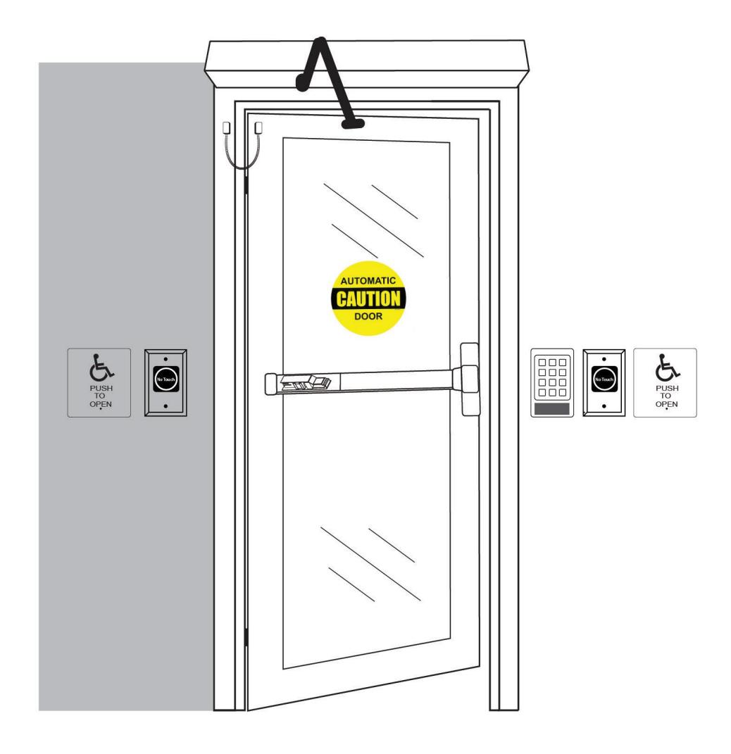
SAMPLE WIRING DIAGRAMS

TABLE OF CONTENTS
| IMPORTANT3 | |
|---|---|
| READ THIS SECTION BEFORE PROCEEDING WITH THE INSTALLATION | |
|
INSTALLATION NOTES
4 |
|
| READ THIS SECTION BEFORE PROCEEDING WITH THE INSTALLATION | |
| SPECIFICATIONS & CERTIFICATIONS5 | |
| POWERING THE OPERATOR6 | |
| MAIN 115VAC ELECTRICAL CONNECTION | |
|
WIRING CONNECTIONS
7 |
|
| DOOR STATUS SWITCH OUTPUT | 8 |
| HARDWIRED PUSH PLATES WITH PUSH SIDE DOOR-MOUNTED SENSOR | 8 |
| WIRELESS PUSH PLATE WITH 24VDC ELECTRIC STRIKE OR MAGLOCK | 9 |
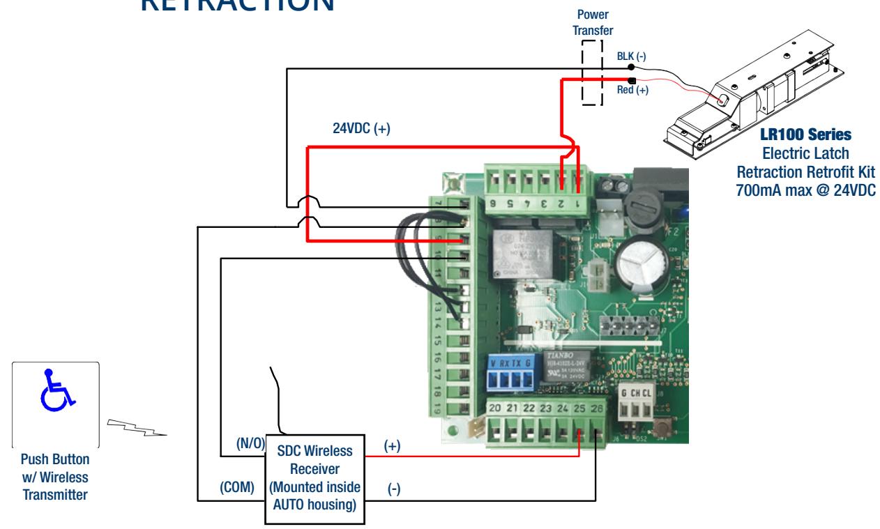
| WIRELESS PUSH PLATE W/ SDC ELECTRIC LATCH RETRACTION | 9 |
| SIMULTANEOUS PAIRS WITHIN A SINGLE HOUSING (BASIC OPERATION) | 10 |
| HANDS FREE BASIC APPLICATION (NO LATCHING OR LOCKING HARDWARE) | 11 |
| HANDS FREE INTERIOR DOOR APPLICATION (WITH ELECTRIC STRIKE) | 12 |
| HANDS FREE & ADA COMPLIANT LATCH RETRACTION EXIT DEVICE APPLICATION | 13 |
| HANDS FREE & ADA COMPLIANT LATCH RETRACTION MORTISE LOCKSET APPLICATION | 14 |
| HANDS FREE & ADA COMPLIANT ELECTRIC STRIKE APPLICATION | 15 |
| ADA COMPLIANT FAIL-SECURE LOCK APPLICATION WITH ACCESS CONTROL (BUSINESS ENTRANCE) | 16 |
|
SDC WIRE GUAGE CHART & VOLTAGE/WIRE CALCULATORS
17 |
|
|
SDC ENGINEERED SYSTEM DESIGN SERVICES
18 |
|
| SDC DOORSNAPTM – RETROFIT MADE EASY19 | |
|
SDC CUSTOMER & TECHNICAL SUPPORT
20 |
|
FOR FULL INSTALLATION INSTRUCTIONS VISIT:
https://sdcsecurity.com/docs/INST-AutoEntry.pdf


IMPORTANT
READ THIS SECTION BEFORE PROCEEDING WITH THE INSTALLATION
Security Door Controls (hereafter referred to as "SDC") recommends that its automated pedestrian door products be installed by a trained automatic door technician and that the resulting performance of the product be in full compliance with the most current version of the American National Standards Institute (ANSI) document A156.19 as well as any applicable building codes and/or fire codes. SDC further recommends that a full inspection of the operating system be performed in accordance with the guidelines of the American Association of Automatic Door Manufacturers (AAADM). SDC recommends this documented inspection be performed upon completion of the installation, as well as following the completion of every service call thereafter. If service is not performed within one year of the previous service action, a routine AAADM inspection should be performed and documented. SDC does NOT recommend service on any of their automated pedestrian door products, by any individual who is not certified as an AAADM inspector.
Following the installation or service of any SDC automated pedestrian door product, if it is deemed unsafe, or is operating in an unsatisfactory manner according to national performance standards or recommended performance guidelines as defined by SDC, repairs should be made immediately. If an immediate repair cannot be made, the product should be disabled, and appropriate measures should be taken to secure the door in a safe position or to enable the door to safely be used manually. During this situation, every effort should be made to notify the owner (or person responsible) of the condition and to advise on corrective actions that must be taken to return the product to safe operation.
LOW ENERGY APPLICATION NOTE
When using the Auto EntryControl™ Series, SDC recommends the use of a door-mounted presence sensor, like the SDC P/N: AUTO-IR, on the push side of the door to be used as a secondary activation device when the door is closing. This type of sensor can be installed at time of installation or can also be retrofitted. This device serves to re-activate the door to the open position should a person enter into the closing path at the push side of the door, as it is closing. Once the door is fully closed, the door-mounted presence sensor is inactive, and a "knowing act" device must then be used for initial activation. SDC considers this device to be essential in reducing the possibility of doors "timing out" and closing before all pedestrians have passed though the doorway.

INSTALLATION NOTES
READ THIS SECTION BEFORE PROCEEDING WITH THE INSTALLATION
- 1. ALL WIRING MUST BE REVIEWED AND APPROVED BY THE PROJECT ENGINEER ASSIGNED TO THE LOCATION FOR ITS CORRECTNESS AND SUITABILITY FOR THE APPLICATION IN WHICH THE EQUIPMENT IS INSTALLED AND OPERATED.
- 2. ALL WIRING MUST CONFORM TO NATIONAL, STATE, AND LOCAL CODES FOR CLASS 2 FIRE PROTECTION AND CONTROL DEVICES
- 3. ALWAYS CONSULT WITH THE AUTHORITY HAVING JURISDICTION (AHJ) BEFORE INSTALLATION.
- 4. WHERE REQUIRED BY CODE, CONNECT FAILSAFE SYSTEMS TO THE LOCAL FIRE LIFE SAFETY SYSTEM FOR EMERGENCY RELEASE.
- 5. ALL LOW VOLTAGE SIGNAL WIRING SHALL BE 22-GUAGE MINIMUM. WHEN POWERING A LOCK, THE MINIMUM INDUCTIVE LOAD (LOCK) POWER WIRE GUAGE SHALL BE DETERMINED USING THE SDC WIRE GUAGE CHART OR ANOTHER VOLTAGE DROP ESTIMATION TOOL. ALL WIRING (SINGLE OR MULTI-CONDUCTOR) SHALL BE COLOR CODED WITHOUT SPLICES. A MINIMUM OF TWO SPARE CONDUCTORS IS RECOMMENDED.
- 6. VOLTAGE MAY NOT BE SPECIFIED ON THESE WIRE DIAGRAMS. VERIFY THAT ALL PRODUCTS ARE VOLTAGE COMPATIBLE.


SPECIFICATIONS & CERTIFICATIONS
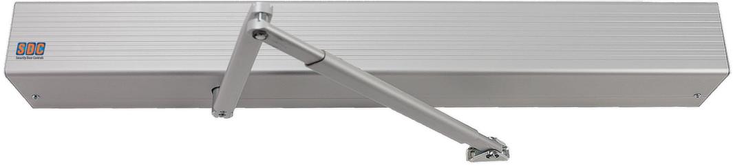
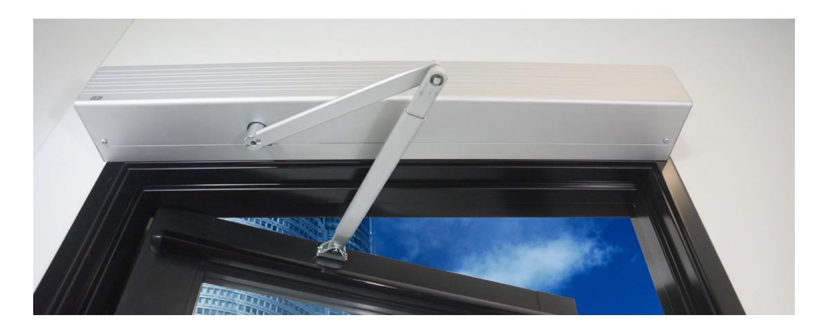
The SDC Auto EntryControl™ Low Energy Swing Door Operator provides safe and reliable point of entry door control featuring a state-of-the-art microprocessor-based controller with electro-mechanical drives. The unit is self-tuning and self-learning while offering non-handed operation, full mechanical stops, and a variety of interface options for sensors, push-plates, fire alarm systems, and electrified locks. A versatile, slim-line design makes it suitable for surface mounted (push/pull) applications.

SPECIFICATIONS
| Power Supply | 115VAC @ 60Hz (+6%, -10%) | 24 VDC Accessory / | ||||
|---|---|---|---|---|---|---|
| Power Consumption | 100W | |||||
| Current consumption | 1A |
Maximum Door Open
ing Angle |
125° | |||
| Motor |
24 VDC Permanent Magnet
with Belt Driven Encoder |
Adjustable Timers & | ||||
| Header Dimension | 4 1/2"H x 4 7/8"D; | length: 39"/45"/51" for 36"/42"/48" |
Timers Potentiome
ters |
|||
| opening, respectively | 3.5A Fuse (F1 located on I/O Board) |
External Selector
Switch Functions |
||||
| Fused Protection | ||||||
| Weight | 22 lbs per Operator Drive Assembly | |||||
|
Ambient Operating
Temperature |
14° to 131°F |
Standard Control
Outputs |
||||
| Ingress Protection |
IP23 - protection from spray water up to
60° from the vertical - i.e. Rainstorm |
Standard Control | ||||
| Maximum Door | 36" Door: 438 lbs | PUSH Arm |
PULL Arm
342 lbs |
Inputs | ||
| Weight |
42" Door: 328 lbs
48" Door: 254 lbs |
256 lbs
198 lbs |
Shipping Weight | 32.2 lbs | ||
|
24 VDC Accessory /
Lock Power Supply |
24 VDC / 1 Amp + |
|---|---|
|
Maximum Door Open
ing Angle |
125° |
|
Adjustable Timers &
Timers Potentiome ters |
• Auto Opening Speed
• Auto Closing Speed • Hold Open Time • Closing Speed w/ Power Off |
|
External Selector
Switch Functions |
• Automatic
• Hold Open • Manual (Off) |
|
Standard Control
Outputs |
• 24 VDC Power Supply
• Lock Relay • Door Status (Fully Open & Fully Closed) |
|
Standard Control
Inputs |
• Interior Activation
• Exterior Activation • Emergency Shutdown • Fire Alarm Input • Safety Device Input |
| Shipping Weight | 32.2 lbs |

CERTIFICATIONS
- ANSI/BHMA A156.19 certified Standard For Power Assist And Low Energy Power Operated Doors
- UL 325 Standard for Door, Drapery, Gate, Louver, and Window Operators and Systems or use on fire and smoke check doors
- Meets ADA Americans With Disabilities Act
- In compliance with FCC 47 CFR Part 15 Class B emissions requirements (USA)
- NFPA 101 Life Safety Code
- ETL Intertek Listed


WARRANTY
Three years from the date of invoice


FEATURES POWERING THE OPERATOR
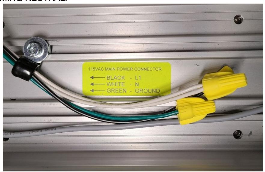
MAIN 115VAC ELECTRICAL CONNECTION
WARNING:
Ensure all incoming electrical power is shut off before proceeding with any high voltage wiring. Failure to do so may result in damage to equipment or personal harm.
• Connect the main power to the Black / White / Green connector on the back-plate. Main power supply: 115 VAC (+6%, -5%), 15A, Single Phase, 60 Hz Dedicated Circuit Attach the incoming 115 VAC line wires to the wiring provided in the header – as shown below.
NOTE : IF THE UNIT HAS TWO WHITE WIRES, BOTH WILL CONNECT TOGETHER TO INCOMING NEUTRAL.
- VERIFY THE OPERATOR'S MAIN POWER SWITCH IS OFF BEFORE ENERGIZING CIRCUIT. THE ORANGE ROCKER SWITCH WILL BE FLIPPED TOWARDS THE TWO BLACK WIRE CONNECTERS.
- VERIFY THAT THE QUICK CONNECT TERMINAL LUGS ARE FIRMLY IN PLACE.
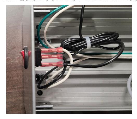
TAKE CARE TO SEPARATE HIGH VOLTAGE AND LOW VOLTAGE CABLING


| Position | Function | Description | ||||||
|---|---|---|---|---|---|---|---|---|
| 1 |
Electric Lock
Relay |
Relay Common | ||||||
| 2 |
Electric Lock
Relay |
N.O. Dry contact – Contact closes upon activation. May be used for fail-secure locks by routing 1 leg of
power though the relay. Relay is triggered by activation inputs 10, 11, or 15. Relay remains energized until door is fully closed again. |
||||||
| TERMINAL STRIP J5 | 3 |
Electric Lock
Relay |
N.C. Dry Contact - Contact opens upon activation. May be used for fail-safe locks by routing 1 leg
of power though the relay. Relay is triggered by activation inputs 10, 11, or 15. Relay remains energized until door is fully closed again. |
|||||
| 4 |
Door Status -
Closed |
N.O. Contact is closed when door is closed. The contact opens as soon as the door opens. | ||||||
| 5 |
Door Status –
Common |
Common contact for door status | ||||||
| 6 |
Door Status -
Open |
N.C. – Contact is closed when door is fully open. The contact opens as soon as the door starts to
close. |
||||||
| 7 | GND | Common GND | ||||||
| 8 | GND | Common GND | ||||||
| 9 | + 24 VDC | 1A Max. Current (Total for terminals 9 & 25) | ||||||
| 10 |
Internal
Activation |
Requires N.O. Contact between input 10 & GND. | ||||||
| 11 |
External
Activation |
Requires N.O. Contact between input 11 & GND. | ||||||
| TERMINAL STRIP J4 | 12 |
Emergency
Closing |
Requires N.C. contact between 12 & GND. Upon open contact, door closes and overrides all
other inputs. Remains jumpered if input is not used. |
|||||
| 13 |
Secondary
Activation |
Requires N.C. contact between 13 & GND. Disabled in full closed position. Used for AUTO-IR
door-mounted presence sensor. |
||||||
| 14 | Stall Safety |
Requires N.C. contact between 14 & GND. Upon open contact, during opening, door stops, then
resumes at reduced speed when input is released. |
||||||
| 15 |
Night Activation
Input |
Requires N.O. Contact between input 15 & GND. Remains capable to activate during Night Mode
(i.e., when dip switch 3 is ON AND On-Off switch is OFF). |
||||||
| 16 | Fire Alarm Input | N.O. contact, when closed causes door closing. All inputs inhibited during closed contact | ||||||
| 17 | Not Used | Requires N.O. contact | ||||||
| 18 | GND | Common GND | ||||||
| 19 | GND | Common GND | ||||||
| 20 | Aux Relay | Auxiliary Relay COM. NOTE: Relay is triggered by input 14 | ||||||
| 21 | Aux Relay | Auxiliary Relay N.O. | ||||||
| 22 | Aux Relay | Auxiliary Relay N.C. | ||||||
| TERMINAL STRIP J6 | 23 |
Alarm Output -
Common |
Common | |||||
| 24 | Alarm Output | N.O. output is closed upon closed contact from fire alarm. LED 2 also illuminates. | ||||||
| 25 | + 24 VDC | 1A max. (Total for terminals 9 & 25) | ||||||
| 26 | GND | Common GND | ||||||


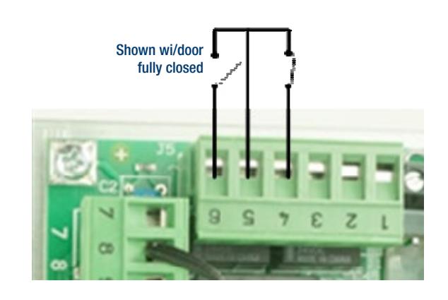
SAMPLE #1 – DOOR STATUS SWITCH OUTPUT
Terminal 4 : Door "Closed" status switch: Contact closes upon full door closed position.
Terminal 5 : Common for both Door Open & Closed Status
Terminal 6 : Door "Open" status switch: Contact is closed when door is fully open.
SAMPLE #2 – HARDWIRED PUSH PLATES WITH PUSH SIDE DOOR-MOUNTED SENSOR
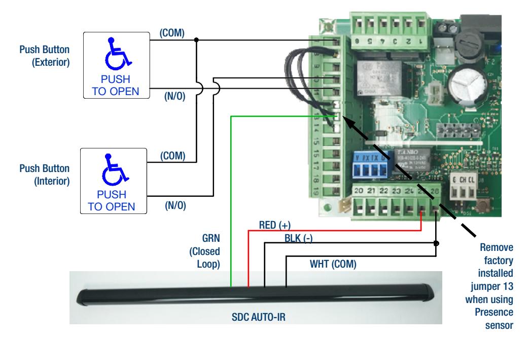
- Push side door-mounted sensor is wired into the secondary activation input (13) at the I/O board. It is a normally closed circuit. When using the AUTO-IR, remove factory installed jumper on terminal 13.
- AUTO-IR will cause re-activation when an obstruction is in the detection zone during the closing cycle.
- Secondary activation input is disabled at the full closed door position.
- Jumpers must remain installed between terminal 8 and 12 & 14 if those inputs are not required for the application.


SAMPLE #3 – WIRELESS PUSH PLATE WITH 24VDC ELECTRIC
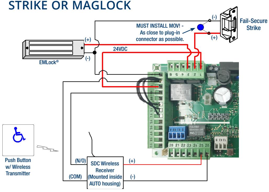
SAMPLE #4 – WIRELESS PUSH PLATE W/ SDC ELECTRIC LATCH RETRACTION


SAMPLE #5 – SIMULTANEOUS PAIRS WITHIN A SINGLE HOUSING (BASIC OPERATION)
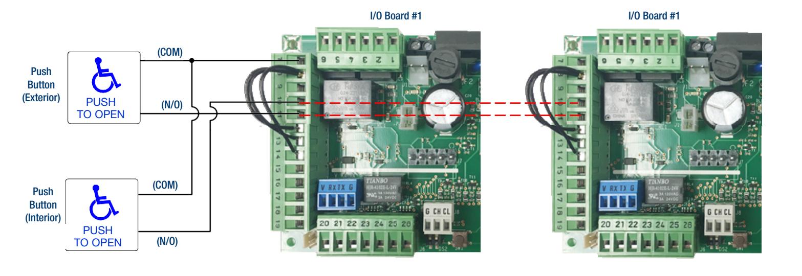
- When wiring controls for use as a simultaneous pair, all required inputs need to be parallel connected between Door #1 and Door #2 as shown as dotted lines in above diagram.
- In the example shown above, hardwired push plates are connected to inputs 7, 10 and 11 at Door #1 and are wired via parallel connection to Door #2.
- In a basic application, N.C. inputs 12, 13 and 14 on each I/O board may have its own jumpers installed. If any of these inputs are required for an application, the jumper will be removed for the respective input on both I/O boards. In place of the jumper, a N.C. switching circuit will connected to Door #1, and a parallel line will be connected to Door #2.
- For simultaneous pairs, each J2 plug-in connector for the mode control is pre-wired in parallel to a single On-Off-Hold switch located in the header end-cap. One switch will control both doors.
- All control adjustments (e.g., speed, time delays) must be made independently at each logic board.
- All dip switches controls must be set independently.


SAMPLE #6 – HANDS FREE BASIC APPLICATION (NO LATCHING OR LOCKING HARDWARE)
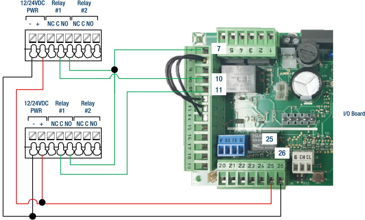
Recommended Wiring:
474U to AUTO Operator – (1) 4C/22AWG ea.

SAMPLE #7 – HANDS FREE INTERIOR DOOR APPLICATION (WITH ELECTRIC STRIKE)
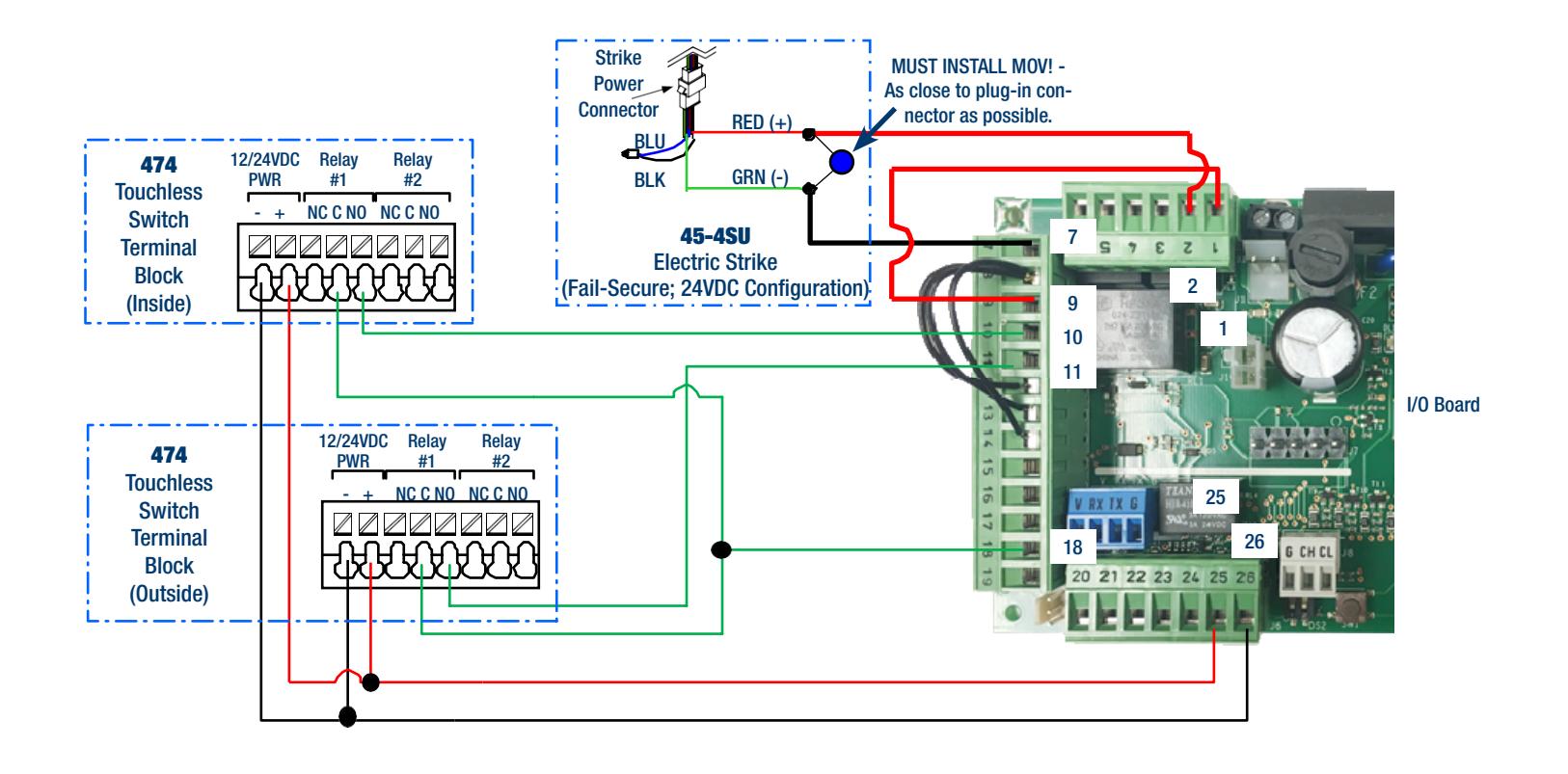
Recommended Wiring:
474U to AUTO Operator – (1) 4C/22AWG ea. 45-4S Electric Strike to AUTO Operator – (1) 2C/18AWG


SAMPLE #8 – HANDS FREE & ADA COMPLIANT LATCH RETRACTION EXIT DEVICE APPLICATION
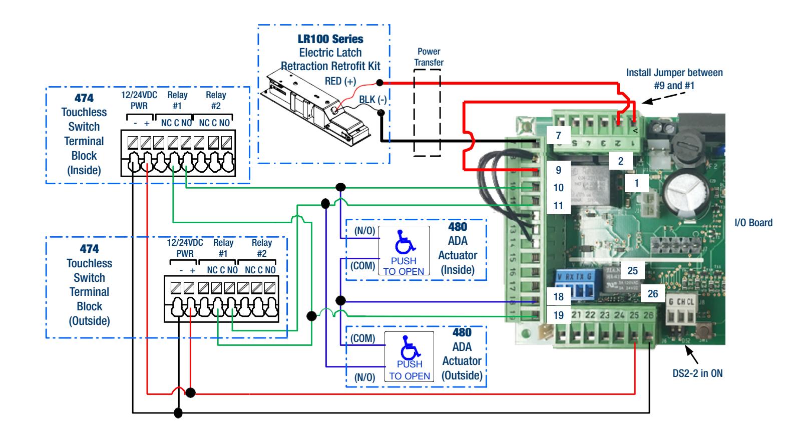
Recommended Wiring:
474U to AUTO Operator – (1) 4C/22AWG ea. ADA Actuators to AUTO Operator – (2) 2C/22AWG ea. LR100 Latch Retraction Kit to AUTO Operator – (1) 2C/18AWG


SAMPLE #9 – HANDS FREE & ADA COMPLIANT LATCH RETRACTION MORTISE LOCKSET APPLICATION
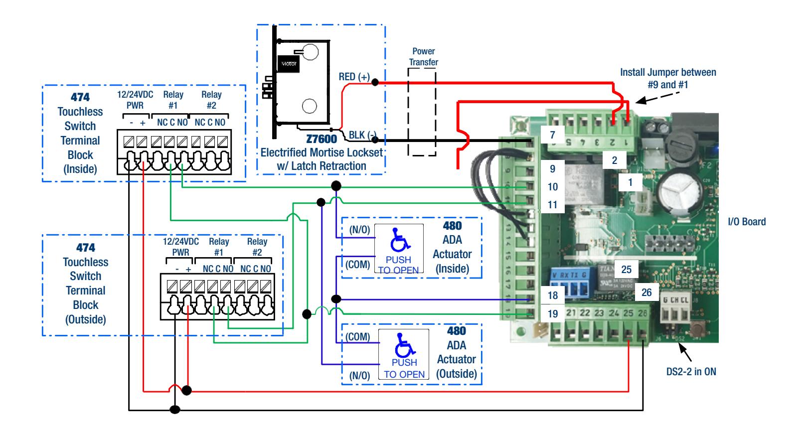
Recommended Wiring:
474U to AUTO Operator – (1) 4C/22AWG ea. ADA Actuators to AUTO Operator – (2) 2C/22AWG ea. Latch Retraction Mortise Lock to AUTO Operator – (1) 2C/18AWG


SAMPLE #10 – HANDS FREE & ADA COMPLIANT ELECTRIC STRIKE APPLICATION
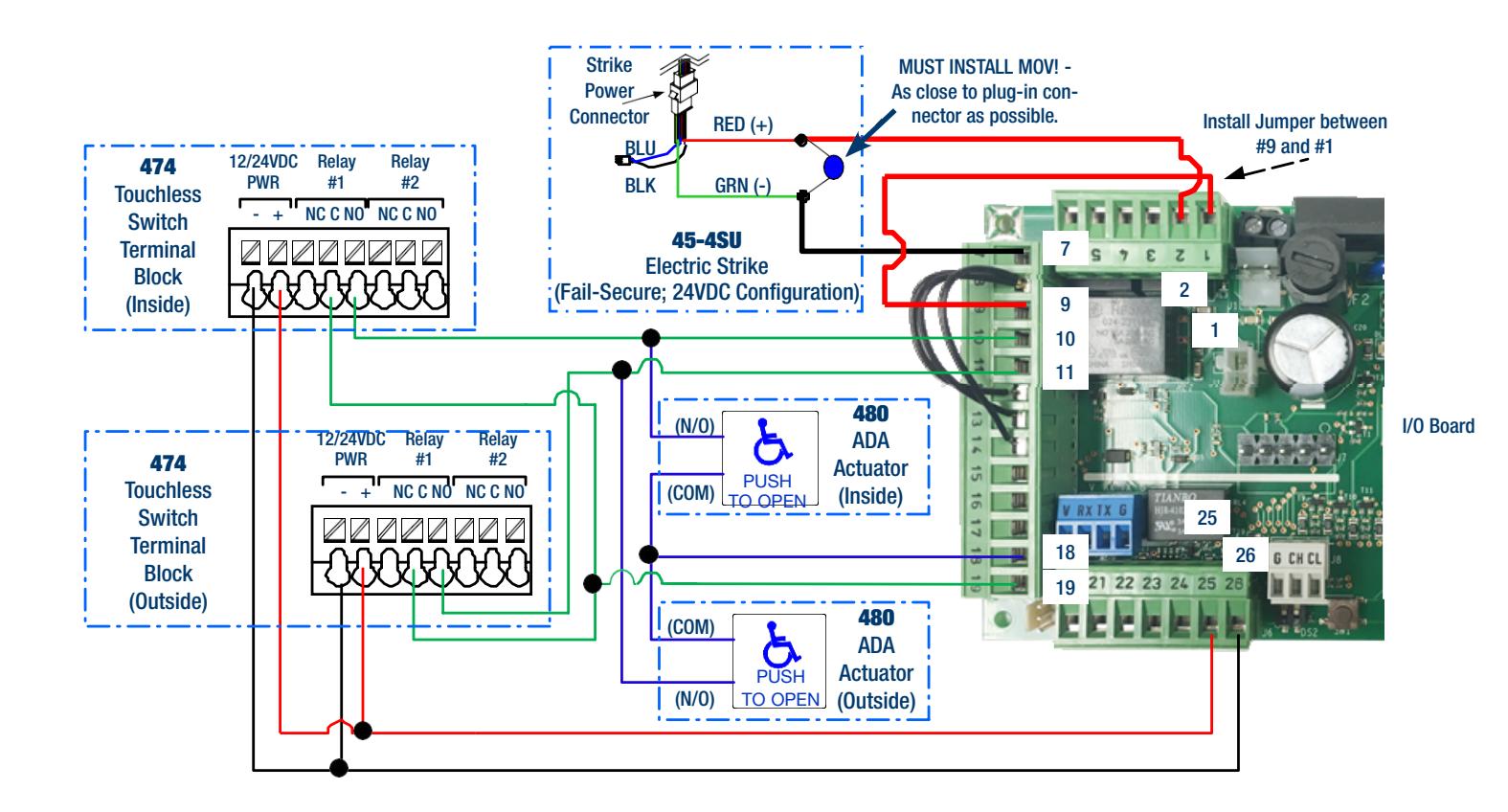
Recommended Wiring:
474U to AUTO Operator – (1) 4C/22AWG ea. ADA Actuators to AUTO Operator – (2) 2C/22AWG ea. Electric Strike to AUTO Operator – (1) 2C/18AWG


SAMPLE #11 – ADA COMPLIANT FAIL-SECURE LOCK APPLICATION WITH ACCESS CONTROL (BUSINESS ENTRANCE)
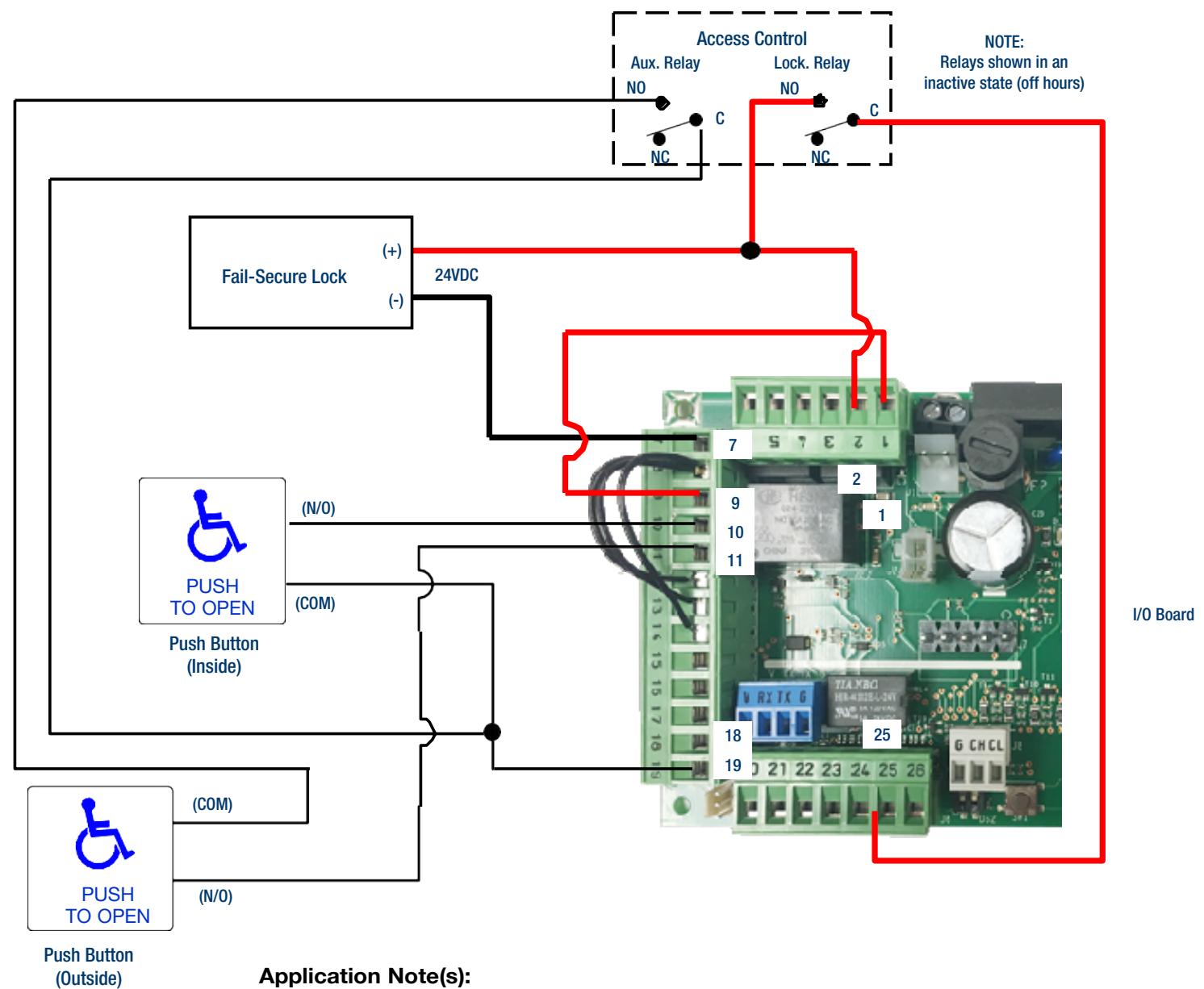
- Application Note(s):
- 1.Outside button is only active when authorized by Access Control.
- 2.Access Control may keep door unlocked during normal business hours.
- 3.Auxiliary Relay follows Lock Relay


SDC WIRE GUAGE CHART & VOLTAGE/WIRE CALCULATORS
FOR VOLTAGE & WIRE CALCULATORS VISIT:
https://sdcsecurity.com/Calculators.htm
SDC has assembled these easy-to-use calculators to assist security dealers, installers, integrators and consultants with designing, specifying and installing electrified access control hardware for their projects.
Ninety percent or more of common installation and operating problems can be avoided by simply ensuring the electrified access control hardware is receiving the power it needs to perform as expected.
These calculators use algorithms based on Ohm's Law - a formula used to calculate the relationship between voltage, current and resistance in an electrical circuit.
OHMS LAW
To Determine an Unknown Voltage: E = I x R
How to calculate:
.25 Amps (I) x 96 Ohms (R) = 24 Volts (E)
To Determine an Unknown Current:
I = E / R
How to calculate: 24 Volts (E) ÷ 96 Ohms (R) = .25 Amps (I)
To Determine an Unknown Current: I = P / E
How to calculate: 6 Watts (P) ÷ 24 Volts (E) = .25 Amps (I)
To Determine an Unknown Wattage: P = E x I
How to calculate:
24 Volts (E) x .25 Amps (I) = 6 Watts (P)
To Determine an Unknown Resistance: R = E / I
How to calculate: 24 Volts (E) ÷ .25 Amps (I) = 96 Ohms (R)
E =Volts
I =Current, Amps R =Resistance, Ohms P =Power, Watts
In real world hardware installations, SDC recommends that you plan for a minimum 5% (or more) Voltage Drop with any electrified access control component. These calculators will determine the maximum distance allowable for a 5% Voltage Drop from the power supply to the furthest load on one circuit
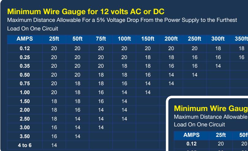
| Minimum Wire Gauge for 24 volts AC or DC | |||||
|---|---|---|---|---|---|
| Maximum Distance Allowable For a 5% Voltage Drop From the Power Supply to the Furthest | |||||
| Load On One Circuit | |||||
| AMPS | 25ft | 50ft | 75ft | 100ft | 150ft | 200ft | 250ft | 300ft | 350ft |
|---|---|---|---|---|---|---|---|---|---|
| 0.12 | 20 | 20 | 20 | 20 | 20 | 20 | 20 | 20 | 20 |
| 0.25 | 20 | 20 | 20 | 20 | 20 | 20 | 20 | 18 | 18 |
| 0.35 | 20 | 20 | 20 | 20 | 20 | 18 | 18 | 18 | 16 |
| 0.50 | 20 | 20 | 20 | 20 | 18 | 18 | 16 | 16 | 16 |
| 0.75 | 20 | 20 | 20 | 18 | 16 | 16 | 16 | 14 | 14 |
| 1.00 | 20 | 20 | 18 | 18 | 16 | 16 | 14 | 14 | |
| 1.50 | 20 | 18 | 18 | 16 | 16 | 14 | |||
| 2.00 | 18 | 18 | 16 | 16 | 14 | ||||
| 2.50 | 18 | 18 | 16 | 14 | 14 | ||||
| 3.00 | 18 | 16 | 14 | 14 | 14 | ||||
| 3.50 | 18 | 16 | 14 | 14 | |||||
| 4 | 16 | 16 | 14 | ||||||
| 5 | 16 | 14 | 14 | ||||||


SDC ENGINEERED SYSTEM DESIGN SERVICES
FOR SYSTEM DESIGN VISIT:
https://sdcsecurity.com/Engineered-System-Design.htm
Ever wish you could save time and money when programming multidoor projects? Troubleshooting product conflicts frustrating you? Are system maintenance headaches eating into your profit ?
SDC's low cost comprehensive services are available when you purchase SDC locks, controller and power supply for door opening applications from your distributor.
-
No more man-hours for programming
✓
- Take your system out of the box, set the dip switches and go.
- Reduced maintenance headaches Wire diagrams eliminate dependence on the original installer. ✓
- Sophisticated and efficient troubleshooting SDC tech support can mock-up and recreate problem scenarios. ✓
- Self diagnostic LED's for quick system status. ✓
- Compatibility Ensured Systems™ When paired with other SDC components, all products are guaranteed to work together. ✓


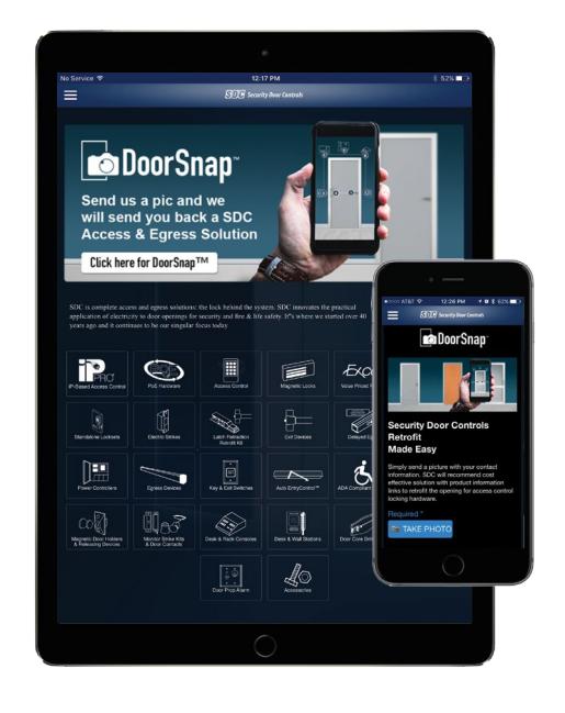
SDC DOORSNAP™ – RETROFIT MADE EASY
FOR MORE INFO VISIT:
https://sdcsecurity.com/doorsnap.htm


Download the FREE SDCSecurity App with DoorSnap™ Now!


SDC CUSTOMER & TECHNICAL SUPPORT
FOR SUPPORT INFORMATION VISIT:
https://sdcsecurity.com/contact.htm

Kelly Boyce Tech Support
(800) 413-8783 x 210 KBoyce@SDCSecurity.com Hours: 6:30 to 3:00 PST
- Application Assistance
- Trouble-shooting
- Product Questions
- DoorSnap™ Facilitator

Michael Lawrence Tech Support
→ (800) 413-8783 x 2XX Michael@SDCSecurity.com ⊕ Hours: 7:30 to 4:00 PST
- Application Assistance
- Trouble-shooting
- Product Questions
- General Customer Support

Taylor Chmelsky Customer Support
√ (800) 413-8783 x 224 □ TaylorC@SDCSecurity.com ⊕ Hours: 7:30 to 4:00 PST
- Order Expediting
- ADI EDI Order Processing
- shipQUICK Inventory Facilitator
- General Customer Support

Andrew Moyer Customer Support
(800) 413-8783 x 213 Andrew@SDCSecurity.com Hours: 8:00 to 4:30 PST
- Chat Support
- General Customer Support
- Pricing
- · Return Material Coordinator
Customer Support Hours:
Monday - Friday from 6:30am to 5:00pm PST Tel: (805) 494-0622 • (800) 413-8783 USA Toll Free