Auto Entry Installation Instructions For Surface Mounted Applications Purchased Before 8-1-18
Open the original PDF document
View PDF

Low Energy Swing Door Automatic Operator
INSTALLATION GUIDE
For Surface Mounted Applications


IMPORTANT
READ THIS SECTION BEFORE PROCEEDING WITH INSTALLATION
Security Door Controls (hereafter referred to as "SDC") recommends that its automated pedestrian door products be installed by a trained automatic door technician and that the resulting performance of the product be in full compliance with the most current version of the American National Standards Institute (ANSI) document A156.19 as well as any applicable building codes and/or fire codes. SDC further recommends that a full inspection of the operating system be performed in accordance with the guidelines of the American Association of Automatic Door Manufacturers (AAADM). SDC recommends this documented inspection be performed upon completion of the installation, as well as following the completion of every service call thereafter. If service is not performed within one year of the previous service action, a routine AAADM inspection should be performed and documented. SDC does NOT recommend service on any of their automated pedestrian door products, by any individual who is not certified as an AAADM inspector.
Following the installation or service of any SDC automated pedestrian door product, if it is deemed unsafe, or is operating in an unsatisfactory manner according to national performance standards or recommended performance guidelines as defined by SDC, repairs should be made immediately. If an immediate repair cannot be made, the product should be disabled, and appropriate measures should be taken to secure the door in a safe position or to enable the door to safely be used manually. During this situation, every effort should be made to notify the owner (or person responsible) of the condition and to advise on corrective actions that must be taken to return the product to safe operation.
LOW ENERGY APPLICATION NOTE
When using the Auto EntryControl ™ Series, SDC recommends the use of a door-mounted presence sensor, like the SDC Auto-IR ™, on the approach side of the door to be used as a secondary activation device. This type of sensor can be installed at time of installation or can also be retrofitted. This device serves to re-activate the door to the open position should a person enter into the closing path at the approach side of the door, as it is closing. Once the door is fully closed, a "knowing act" device must then be used for initial activation. SDC considers this device to be essential in reducing the possibility of doors "timing out" and closing before all pedestrians have passed though the doorway.

TABLE OF CONTENTS:
| Page(s) | Contents | |
|---|---|---|
| IMPORTANT | READ IMPORTANT NOTICE BEFORE BEGINNING THE | |
| INSTALLATION OF THIS PRODUCT | ||
| 2 | Important Notice | |
| 4 |
Product
Description & Specifications |
|
| 5-8 |
STEP 1:
Header Backplate Installation |
|
| 9-10 |
STEP 2:
Re-mounting Operator Control Assembly |
|
| 11-17 |
STEP 3:
Install The Arm Assembly - Standard Applications |
|
| 18-19 |
STEP 4:
Adjusting The Mechanical Stops |
|
| 20-22 |
STEP 5:
Setting The Dip Switches |
|
| 23 |
STEP 6:
Wiring Connections |
|
| 24 |
STEP 7:
Adjusting The Control |
|
| 25 |
STEP 8:
120 VAC Connection |
|
| 26-29 |
STEP 9:
Power On & Tune-In |
|
| 30 | Troubleshooting | |
| 31-32 |
Appendix -
Adjusting The Chain Tensioner |
|
| 32-37 |
Appendix –
Wiring Diagrams |
|
| 38 |
Appendix -
Lock Relay Function |
|
| 39-40 |
Appendix -
Fire rated Door Application |
|

PRODUCT DESCRIPTION & SPECIFICATIONS
The SDC Auto EntryControl ™ Low Energy Swing Door Operator provides safe and reliable point of entry door control featuring a state-of-the-art microprocessor-based controller with electro-mechanical drives. The unit is self-tuning and self-learning while offering non-handed operation, full mechanical stops, and a variety of interface options for sensors, push-plates, fire alarms, and electrified locks. A versatile, slim-line design makes it suitable for surface mounted (push/pull) applications.
| Power Supply | 115 VAC (+6%, -10%) 60Hz | ||
|---|---|---|---|
|
Consumption
Power |
100W | ||
|
Current
Consumption |
1A | ||
| Motor | 24 VDC Permanent Magnet With Belt Driven Encoder | ||
|
Dimensions
Header |
4-1/2" x 4-7/8" (l x w x d);
length: 39"/45"/51" for 36"/42"/48" opening, respectively |
||
|
Protection
Fused |
3.5A Fuse ("F1" located on I/O Board) | ||
| Motor Assembly Weight | 22 lbs. Per Operator Assembly | ||
|
Ambient
Operating Temperature |
-4° to 131° F | ||
|
Protection
Ingress |
IP23 (protection from spray water up to 60° from vertical) | ||
|
Weight
Door Maximum |
PUSH ARM
PULL ARM 36" Door: 438 lbs. 342 lbs. 42" Door: 328 lbs. 256 lbs. 48" Door: 254 lbs. 198 lbs. |
||
|
VDC Accessories
24 Power Supply |
24 VDC / 500 mA max. | ||
|
Adjustable
Speeds & Timers |
Opening Speed
Closing Speed Hold Open Time |
||
|
Standard
Selector Switch Functions |
Automatic
Hold Open Manual (Off/Night) |
||
|
Standard
Control Outputs |
24 VDC Power Supply
Door Status (Fully Open and Fully Closed) Malfunction Alarm Signal |
||
|
Standard
Control Inputs |
Interior Activation
Exterior Activation Emergency Shutdown Fire Alarm Input Safety Device Input (Door mounted presence sensor) |
||
STEP 1 : HEADER BACKPLATE INSTALLATION
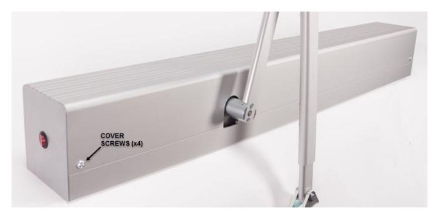
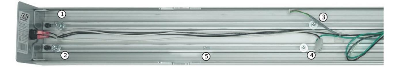
Remove the header front cover by removing the 2 hex screws on the top & bottom of the operator.
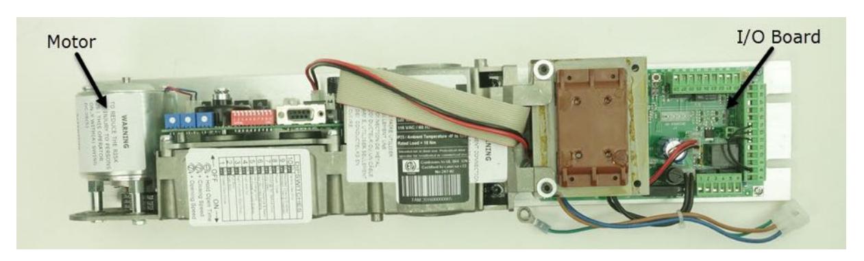
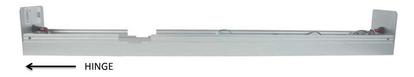
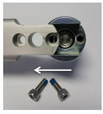
The motor assembly is factory mounted to the slotted back plate using FIVE hex bolts. The bolts attach to nuts that slide in the two slotted tracks of the back plate.
The motor assembly should be removed before installing the backplate. NOTE: When you order a PULL or PUSH operator, the motor assembly will be shipped from the factory in the appropriate PULL or PUSH orientation. Take note of the orientation before removing the motor assembly (i.e. Is the motor towards the inside of the housing or the edge of the housing)
To remove the motor assembly:
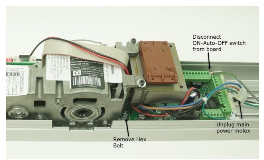
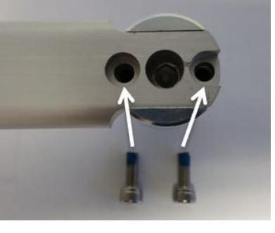
First, remove the single hex bolt and washers located behind the transformer (a ball end hex wrench is recommended).
Disconnect the ON-Auto-OFF connector from the board and unplug the molex main power connector.
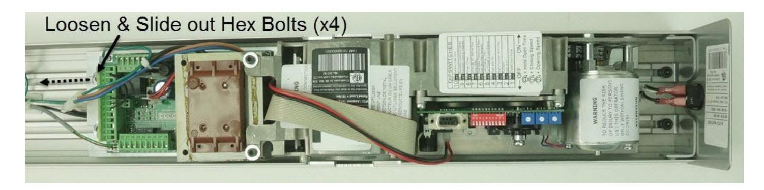
Locate & loosen the 4 side hex bolts (see below). NOTE: One of the four hex bolts is fastened to the green ground wire of the power connector. This bolt will need to be removed temporarily to disconnect the green wire.
Slide the bolts away from the motor assembly allowing the assembly to be removed.
Determine the handing of the door.
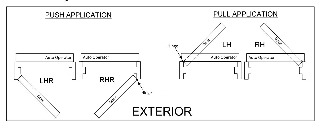
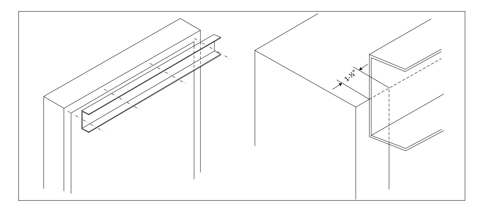
The backplate will mount with the edge nearest the spindle cutout towards to the hinge.
Mount the backplate to the top door frame using 5 or 6 of the screws provided, or use appropriate fasteners for the type of frame. Install reinforcement as required.
- Push side mounting: Bottom of the backplate is flush with bottom of the door frame. For hollow metal applications, drop 1/8"below the frame.
- Pull side mounting: Bottom of the backplate is mounted 1.5" up from bottom door frame.
- For a 36" opening, backplate should overlap each hinge jamb tube by 1.5".
- Refer to the APPENDIX for fire rated door applications.
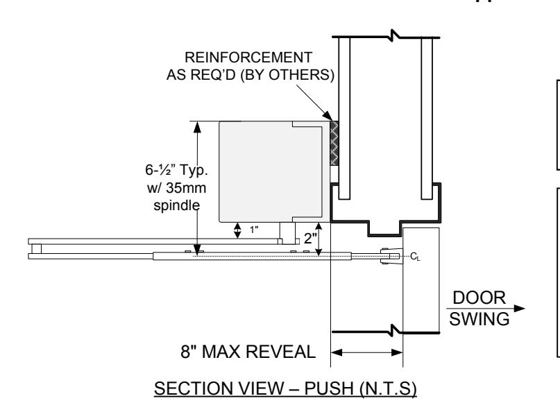
PUSH-ARM APPLICATIONS :
Bottom of operator header is flush with bottom of top frame.
NOTE:
A 35 mm spindle adaptor is included with all standard push arm applications. This requires that the header assembly be mounted as shown at left, flush with bottom of frame face.
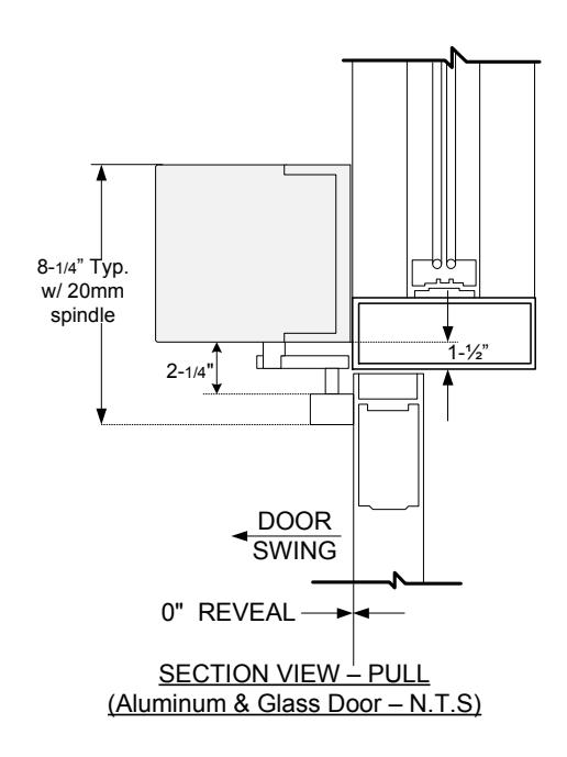
PULL ARM APPLICATIONS: Bottom of operator is mounted 1.5" up from the bottom side of top door frame
Backplate should overlap hinge jamb tube by 1.5" (See figure below).
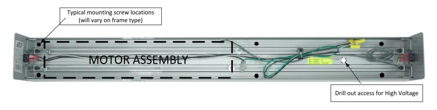
STEP 2 : RE-MOUNT THE MOTOR ASSEMBLY
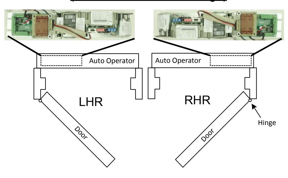
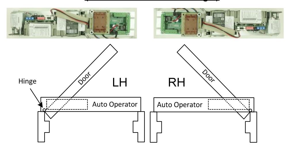
The orientation of the motor assembly will depend on the door handing & application (see below).
PUSH APPLICATION (I/O board towards the hinge)

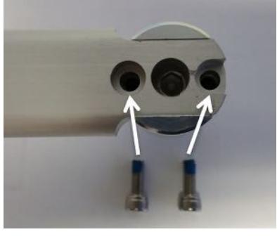
Before reinstalling the motor, take notice of the location of the 4 mounting hex bolts, and the nut for the 5th mounting bolt
Place and Hold the motor assembly up to the header, allowing it rest on the slotted tracks.
Slide in the 4 outer hex bolts and tighten loosely. Slide the entire assembly left or right to line up the 5th hex bolt nut with the mounting hole from the bolt removed on page 5 (near the transformer). Reinsert the hex bolt and washers removed on page 5.
Temporarily remove one of the mounting hex bolts and washers from the I/O board side of the assembly to allow the ground wire ring connector to be reconnected.
After all 5 hex bolts have been inserted, reposition the whole assembly so that the spindle attachment point is centered with the spindle cutout, as shown on the bottom of page 5. Secure the motor assembly by tightening all 5 hex bolts.
Reconnect the ON-Auto-OFF connector to the I/O board and the molex main power connector.
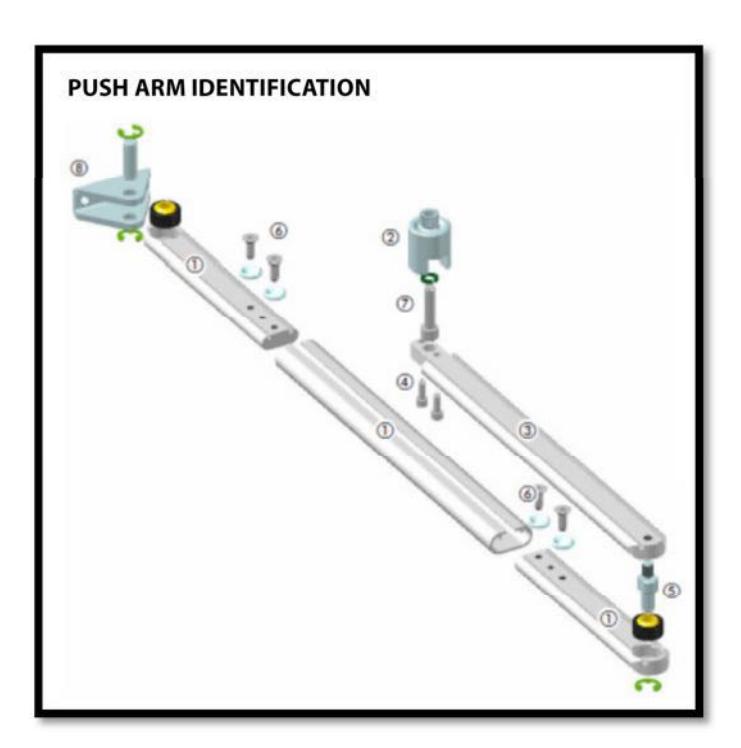
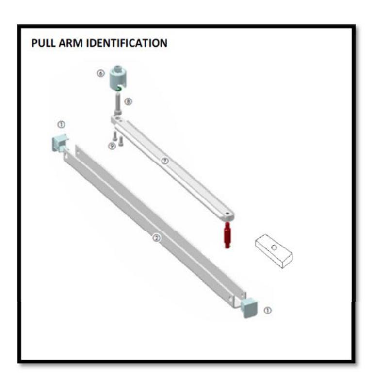
STEP 3 : INSTALL THE ARM ASSEMBLY - STANDARD APPLICATION
See Arm Installation instructions included with each arm for assembly details
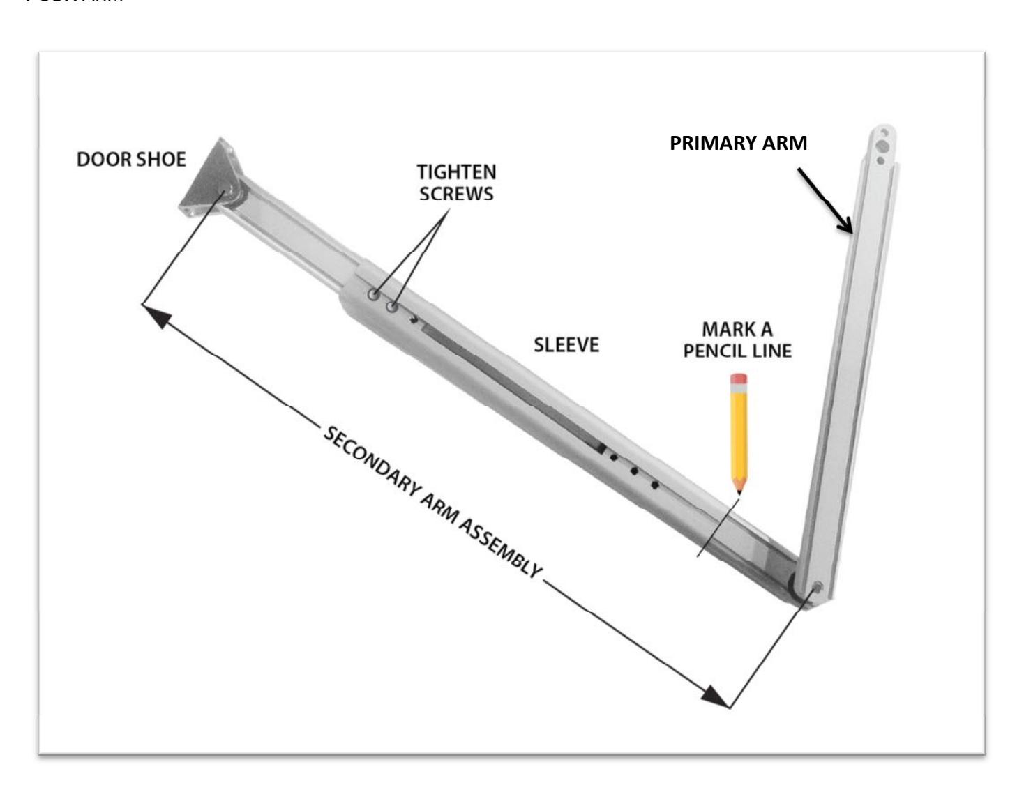
PUSH ARM ASSEMBLY:
- 1. Secondary Arm With Sleeve
- 2. Spindle Adaptor
- 3. Primary Arm
- 4. Spindle/Arm Attachment Screw
- 5. Pivot Stud (Pre-assembled)
- 6. Secondary Arm Attachment Screws with Dimple Washers
- 7. Spindle Adaptor Bolt
- 8. Door Shoe
PULL ARM ASSEMBLY:
- 1. End caps
- 2. Slide Track
- 3. Slide Block Sub-Assembly
- 4. Slide Blocks
- 5. Slide Block Separator
- 6. Slide Block Stud
- 7. Primary Arm
- 8. Spindle adaptor Bolt
- 9. Spindle Adaptor/Arm Attachment
Follow the instructions listed below for a standard arm application using a "push" or a "pull" application.
PUSH ARM APPLICATION
• Ensure the main power supply is removed or shut off at the control.
-
Prior to beginning the push arm installation, gather the following information about the application:
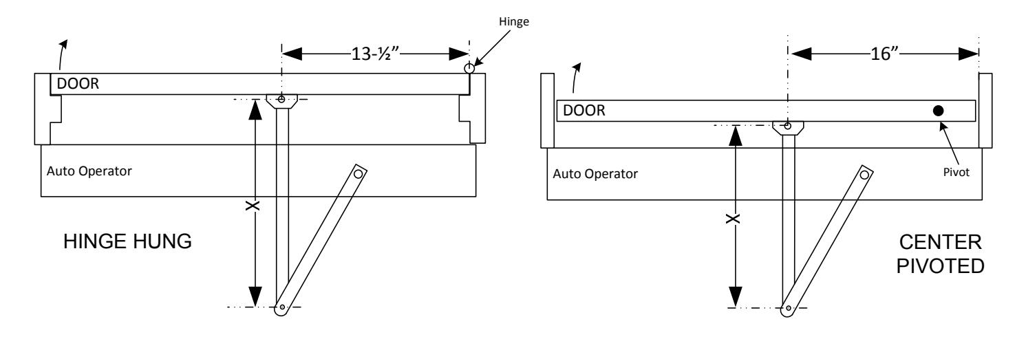
- o Door configuration (Hinge Hung or Center Pivoted)
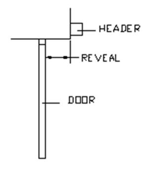
- o Reveal distance (inches)
- The door shoe and short arm comes pre-assembled it is not necessary to take the assembly apart.
- Use the chart below to determine the prescribed length of the secondary arm assembly and note the dimensions.
| Reveal |
HingeHung
X Dim. |
Center
Pivot X Dim. |
|||
|---|---|---|---|---|---|
| 0" | 13" | 16" | |||
| 1" | 14" | 17" | |||
| 2" | 15" | 18" | |||
| 3" | 16" | 19" | |||
| 4" | 17" | 20" | |||
| 5" | 18" | 21" | |||
| 6" | 19" | ||||
| 7" | 20" | ||||
| 8" | 21" | ||||
| FOR DEEPER REVEAL DISTANCES UP TO 13", USE ARM EXT. | |||||

-
Before installing any portion of the door arm assembly, it is easiest to lay the arm out on a flat surface and insert the secondary and primary arm into the sleeve as it will be when installed on the door:
- o Slide the short arms within the sleeve to obtain the prescribed "X" dimension. If the reveal falls between two of the values on the chart, use (Reveal + 13") for hinge hung doors, or (Reveal + 16") for Center Pivot doors
- o Tighten the screws on the short arm that is connected to the door shoe.
- o Double-check the "X" dimension of the arm this is the distance between the center of the hole at the door shoe and the center of the hole at the pivot point of the primary arm (as shown).
- o Mark a pencil line at the edge of the sleeve where it overlaps the short arm that is connected to the primary arm. This will make it easier when positioning the primary arm for final installation.
- o After marking the line, remove the primary arm assembly only from the sleeve.
PUSH ARM
• Install the door shoe per the door hinge / pivot configuration:
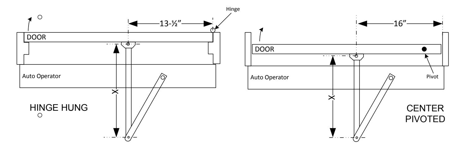
- o Hinge Hung Doors: Centerline of door shoe at 13.5" in from inside of hinge jamb
- o Center Pivot Doors: Centerline of door shoe at 16" in from inside of pivot jamb
- o The horizontal centerline of the door shoe will be at 2" below the bottom of the backplate
- o Do NOT install the primary arm until instructed to do so
• Attach the spindle to the primary arm:
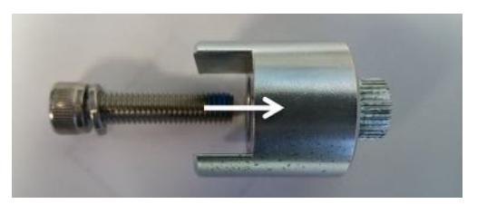
Insert the large hex bolt and washer into the spindle adaptor
Then, horizontally slide the adaptor onto the primary arm until the two mounting holes of spindle line up with the corresponding holes on the primary arm. The spindle is intended to fit tightly. Secure the spindle using the two small hex bolts.
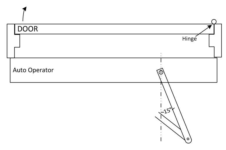
• Insert the primary door arm and spindle adaptor into the operator at a position where the primary arm is approximately 10-15 degrees from perpendicular, in the direction of the hinge.
- Tighten the spindle adaptor to the operator
- Turn & Slide the primary short arm into the sleeve to the pencil marked position. Tighten the hex screws within the sleeve once complete

• With the door closed, the secondary arm should be at approximately 90 degrees to the face of the door as shown - it is not imperative that the arm be at this "exact" position
- Upon final installation of door arm assembly, press SW1 to launch a new setup - this is required for the control to learn the new door stroke. Refer to Steps 8 & 9, Power On & Tune In Sections for more information.
- Upon successful completion of setup, proceed with remainder of installation .
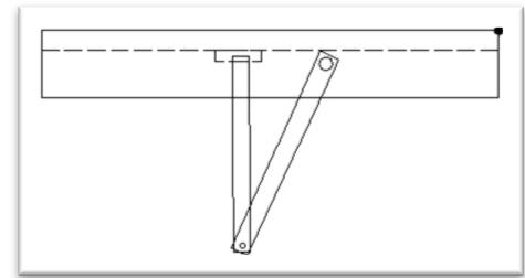
PULL ARM APPLICATION:
- Ensure the main power supply is removed or shut off at the control.
- Install the slide track assembly to the door at the specified location.
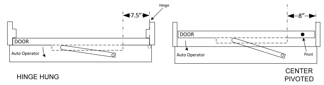
| HINGE HUNG DOORS | CENTER PIVOTED DOORS | |||
|---|---|---|---|---|
| PULL APPLICATION | Inside face of jamb to back edge of | Inside face of pivot jamb to back | ||
| slide track | Inside face of pivot jamb to spindle | edge of slide track | ||
| 7.5" | 10.5" | 8" | ||
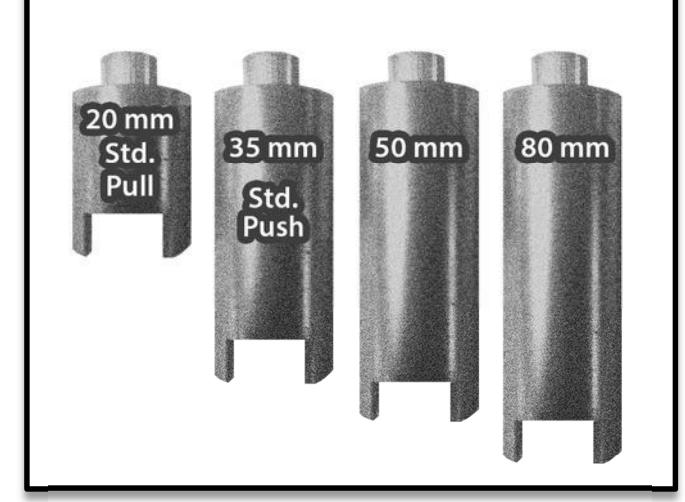
- When using the standard 20mm spindle, the top of the track should be approximately 2-1/4" below the operator header. Attach the track with the screws provided.
- The pull arm assembly is a fixed dimension and is not adjustable in length. The slide block and pull arm come pre-assembled from the factory.
- Attach the spindle to the pull arm:
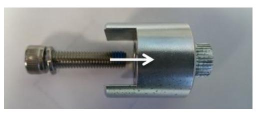
Insert the large hex bolt and washer into the 20mm spindle adaptor
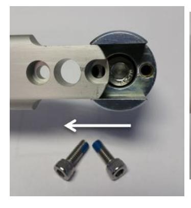
Then, horizontally slide the adaptor onto the primary arm until the two mounting holes of spindle line up with the corresponding holes on the primary arm. The spindle is intended to fit tightly. Secure the spindle using the two small hex bolts.
- Insert it into the operator at a position that allows the slide block to go in the door-mounted slide track. Once it is in place, tighten the main adaptor bolt to secure the arm to the operator.
- Apply power to the unit & Press and hold button SW1 to launch a new setup (see Steps 8 & 9)
STEP 4 : ADJUSTING THE MECHANICAL STOPS
- CAUTION DO NOT REMOVE THE STOPS
- IMPORTANT Step 4 may be optional depending on your application. See note on the following page. If
- The mechanical stops are located on the top or bottom of the operator, depending on the handing of the door.
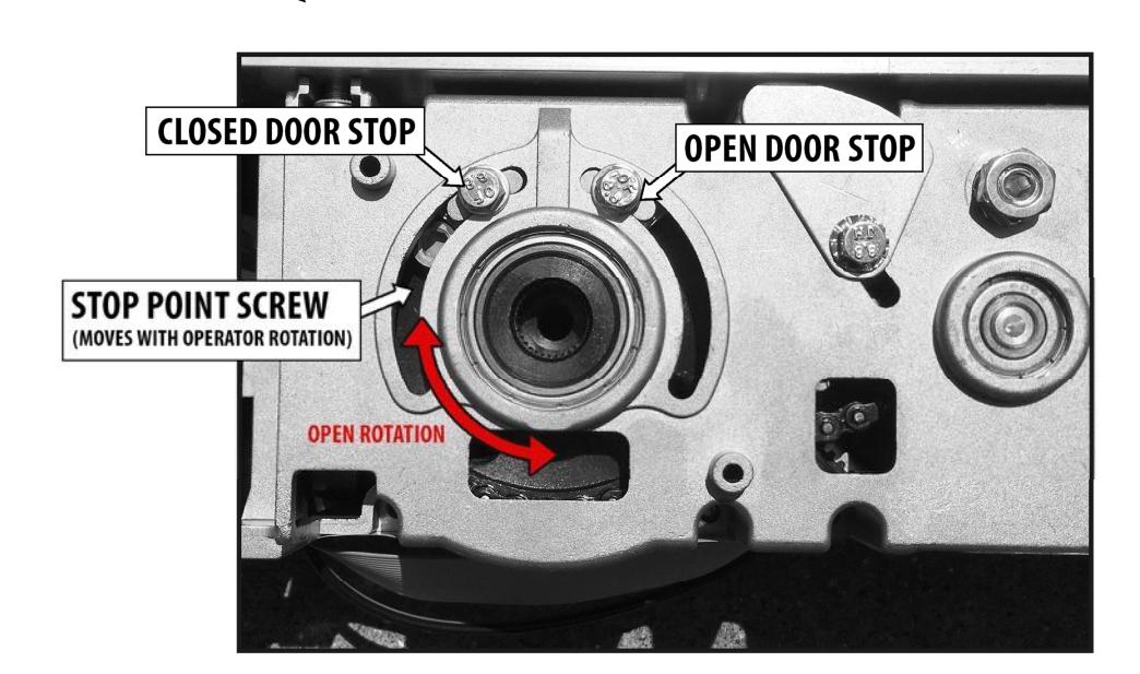
- The opening direction is always counter-clockwise rotation when viewed as shown above
- Loosen the bolts on the desired stop (do not remove bolts) and move to the desired position
- Re-tighten bolts securely and test the door travel stroke
IMPORTANT
- If the door closes against a fixed door stop that is door frame mounted, the CLOSED DOOR STOP does NOT have to be adjusted to meet the stop-point screw. The step is then optional.
-
The OPEN DOOR STOP setting is also optional. A "SOFT STOP" is sometimes preferred depending upon the application, particularly if heavy manual use is anticipated. The Soft Stop is simply a method of programming the door for the open position by means of a temporary stop method; such has holding your foot at the desired location during programming. To use the Soft Stop method, perform the following:
- o Press the automatic setup button (SW1 as shown on page 29), to allow the start of the setup process
- o Position your foot on the ground at the desired full open door position. Allow the door to open and hit your foot during the first opening cycle during setup - you can then remove your foot from that position.
- o Allow the setup to complete itself thereafter
- o The door will open automatically thereafter to that position. When the door is pushed further than the soft stop location it will return to the programmed point automatically.
- o Do not use the soft stop method if there is anything behind the open door that the door could be repeatedly pushed into from manual openings - such as a glass wall.
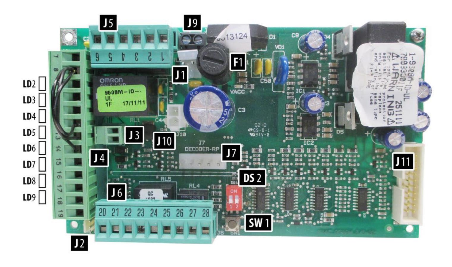
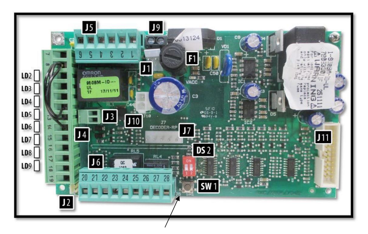
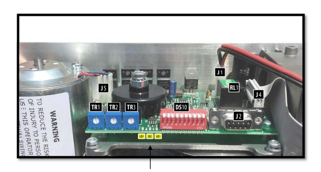
STEP 5: SET THE DIP SWITCHES ON THE I/O BOARD
- Set the dip switches according to the application. The default settings are usually sufficient for most applications.
- Dip switches are used to apply specific functions to the control.
- There are 2 sets of dip switches. A 2-position on the I/O board (DS2), and a 10-position on the adjustment board (DS10).
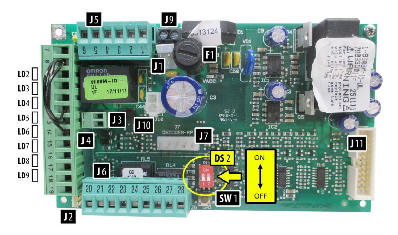
| Description | ON | OFF | |||
|---|---|---|---|---|---|
| 1 | Push-N-Go Hold Time | The hold time is set by TR3 | 3 Seconds (Default) | ||
| potentiometer at adjustment | |||||
| DS2 | board | ||||
| 2 | Electric Lock Delay | 500 milliseconds | 200 milliseconds (Default) | ||
STEP 5 Cont. : SET THE DIP SWITCHES ON THE ADJUSTMENT BOARD
• Set the dip switches according to the application. See the table on the next page.
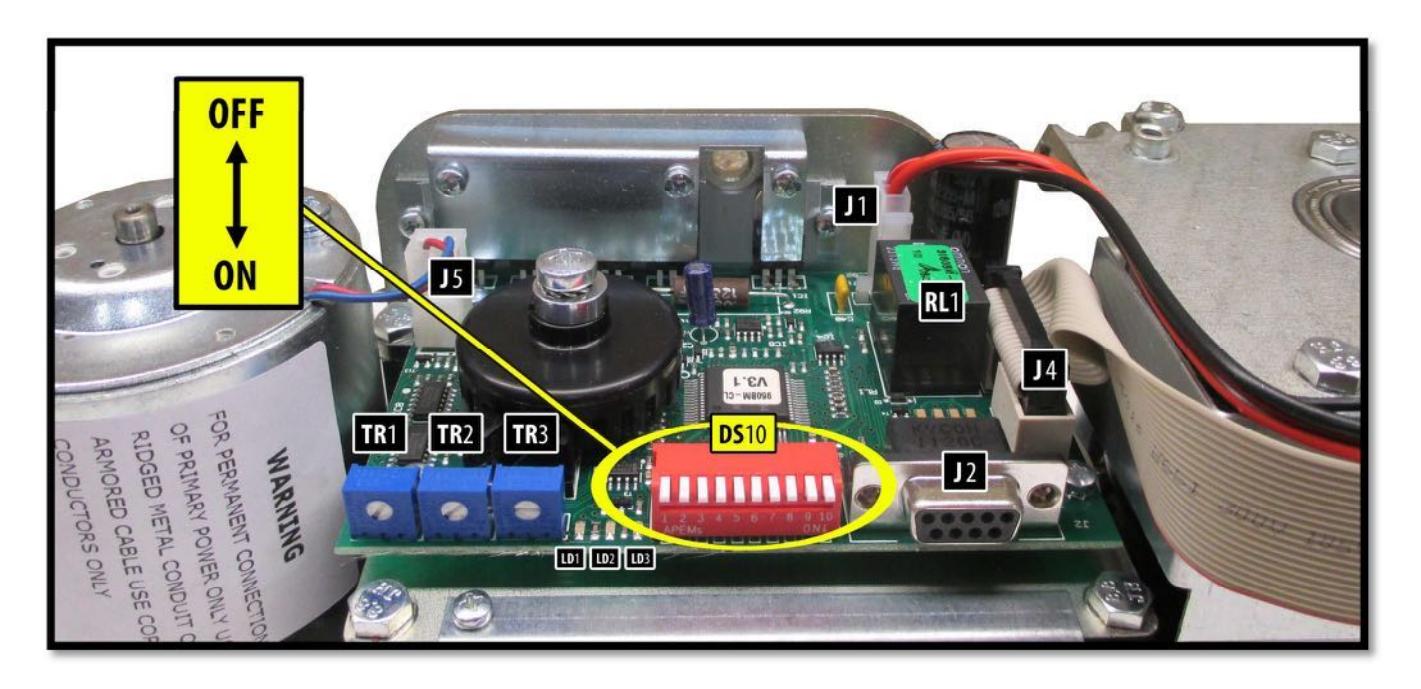
| Description | ON | OFF | |
|---|---|---|---|
| 1 | Closed Door Force | Additional force applied while door is | Disabled (Default) |
| in closed position. Be sure to maintain | |||
| ANSI compliance if using on low | |||
| energy application. Cannot exceed 30 | |||
| lbf to get door moving from jamb. | |||
| 2 | Push / Pull Arm |
Use
for Slide Arm Applications. |
Push Arm Application. |
| Operator stroke at 90° degrees or | Operator stroke 90° or | ||
| less. Visible change in performance | greater. (Default) | ||
| may not always be noticeable. | |||
| 3 | Night Function (Exit | Allows activation at input 10 when | Disabled. The On/Off |
| Only) |
On-Off
switch is in OFF (night |
switch, when OFF, requires | |
| function) position. | manual operation of the | ||
| door. (Default) | |||
| 4 | Push and Go | Enabled | Disabled (Default) |
| 5 | Full Power / Low | Low Energy performance enabled. 5 | Disabled. Control can be |
| Energy | seconds to open, 7 seconds hold | adjusted for full power or | |
| open, 5 seconds to close. Speed & | low energy operation via | ||
|
time
potentiometers are disabled. |
potentiometers. (Default) | ||
| Settings are fixed. | |||
| 6 | Not used for Low | Set to OFF for Low Energy | |
| Energy Applications | Applications | ||
| 7 | Not used for Low | Set to OFF for Low Energy | |
| Energy Applications | Applications | ||
| 8 | Power Close | Additional closing force applied for | Disabled (Default) |
| final 10 degrees of closing. | |||
| 9 | Assisted Manual | Enabled assisted closing following a | Disabled assisted closing |
| Closing*** | manual opening | following a manual opening | |
| 10 | FACTORY USE ONLY |
*** SDC recommends the use of a door-mounted secondary activation device when dip switch 9 is ON - Enabled.

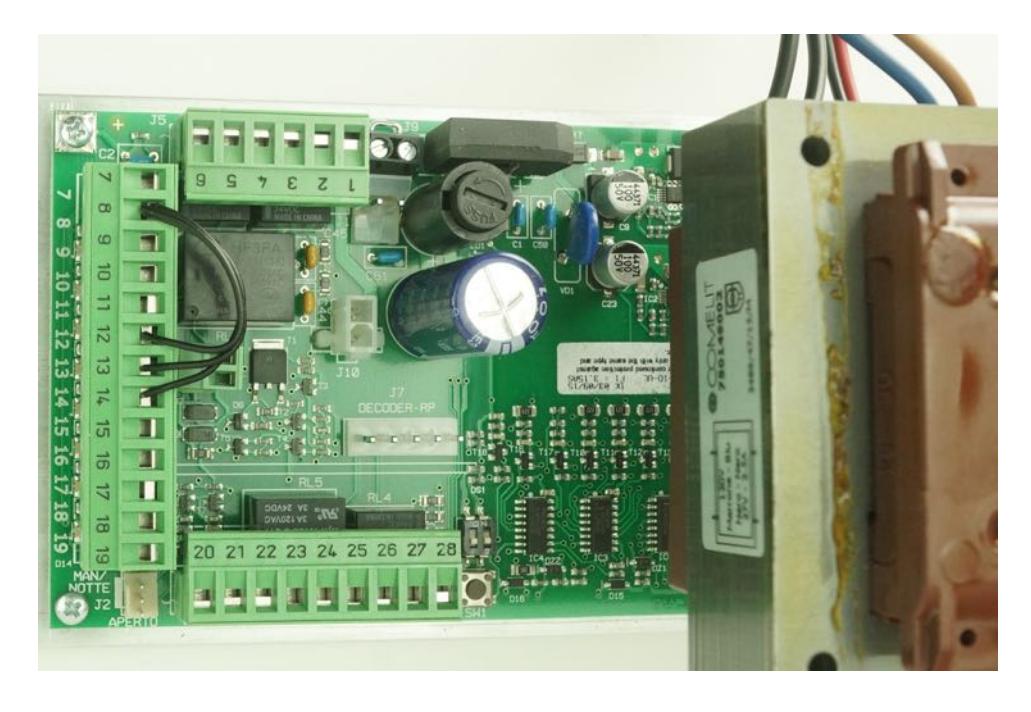
STEP 6: WIRING CONNECTIONS (wiring diagrams are located in the Appendix)
I/O BOARD CONNECTIONS
| Position | Function | Description | |
|---|---|---|---|
| 1 | Electric Lock | Common | |
| Relay | |||
| 2 | Electric Lock | N.O. Dry contact – Contact closes upon activation. May be used for fail-secure locks by | |
| Relay | routing 1 leg of power though the relay. Relay is triggered by activation inputs 10, 11, or | ||
| 16. Relay remains energized until door is fully closed again. | |||
| 3 | Electric Lock | N.C. Dry Contact - Contact opens upon activation. May be used for fail-safe locks by | |
| Relay | routing 1 leg of power though the relay. Relay is triggered by activation inputs 10, 11, or | ||
| TERMINAL STRIP J5 | 16. Relay remains energized until door is fully closed again. | ||
| 4 | Door Status - | N.O. Contact is closed when door is closed. The contact opens as soon as the door opens. | |
| Closed | |||
| 5 | Door Status – | Common contact for door status | |
| Common | |||
| 6 | Door Status - | N.C. – Contact is closed when door is open. The contact opens as soon as the door starts | |
| Open | to close. This input can be used for motor connection at lockout relay when power is | ||
| looped through, thus switching power on when door is open. | |||
| 7 | GND | Common GND | |
| 8 | GND | Common GND | |
| 9 | + 24 VDC | .5A Max. Current | |
| 10 | Internal | Requires N.O. Contact between input 10 & COM. Remains capable to activate when dip | |
| Activation | switch 3 is ON AND On-Off switch is OFF. | ||
| 11 | External | Requires N.O. Contact between input 11 & COM. | |
| Activation | |||
| 12 | Emergency | Requires N.C. contact between 12 & COM. Upon open contact, door closes and overrides | |
| Closing | all other inputs. Remains jumpered if input is not used. | ||
| TERMINAL STRIP J4 | 13 | Secondary | Requires N.C. contact between 13 & COM. Disabled in full closed position. |
| Activation | |||
| 14 | Not Used | Requires N.C. contact between 14 & COM. | |
| 15 | Not Used | Not Used | |
| 16 | Fire Alarm | N.O. contact, when closed causes door closing. All inputs inhibited during closed contact | |
| Input | (not available on all software versions) | ||
| 17 | Not Used | Requires N.O. contact | |
| 18 | GND | Common GND | |
| 19 | GND | Common GND | |
| 20 | Aux Relay | Auxiliary Relay NOTE: Relay is triggered by input 14 | |
| 21 | Aux Relay | Auxiliary Relay N.O. | |
| 22 | Aux Relay | Auxiliary Relay N.C. | |
| 23 | Alarm Output - | Common | |
| Common | |||
| 24 | Alarm Output | N.O. output is closed upon closed contact from fire alarm. | |
| 25 | + 24 VDC | .5A max. (Total for terminals 9 & 25) | |
| GND | Common GND | ||
| 26 |
STEP 7: ADJUSTING TIMERS
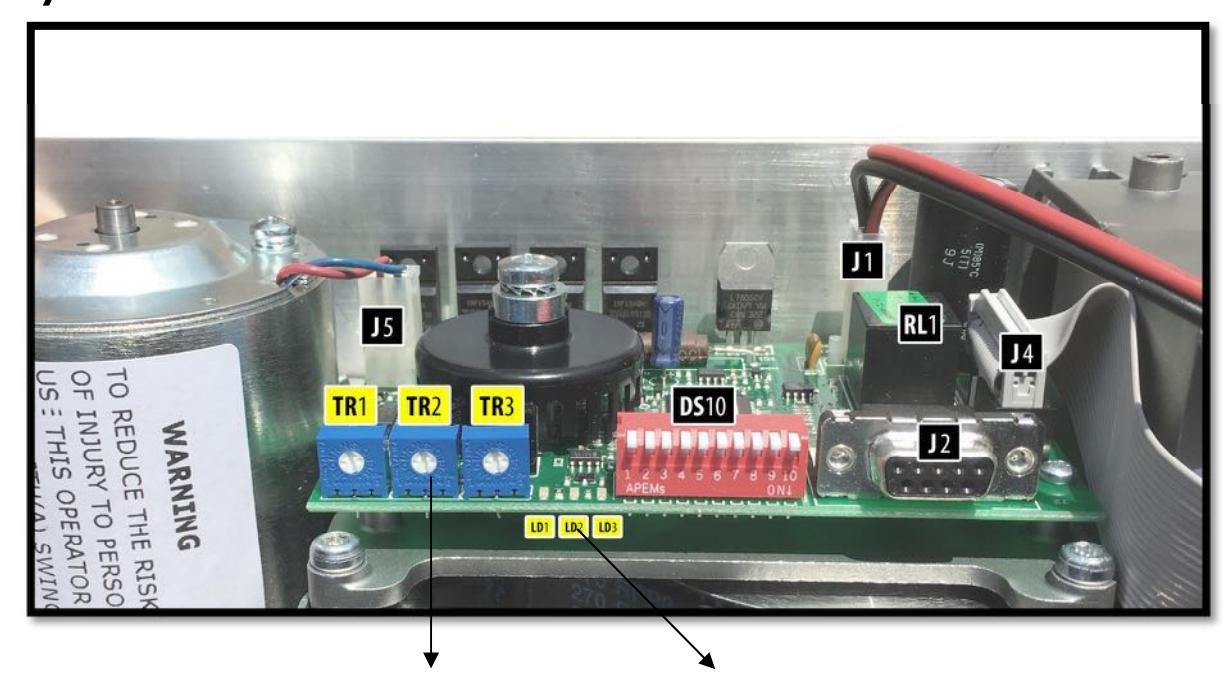
| Adjustment Board Trimmers | Adjustment Board LEDs | ||
|---|---|---|---|
|
TR1
Opening Time Adjustment (4 – 10 secs) |
GREEN LED Indicates motor power | ||
|
TR2
Closing Time Adjustment (4 – 10 secs) |
LD2 | Rapid flashing RED indicates setup in progress | |
|
TR3
Hold Open Time (0 – 30 secs) |
LD2 | Slow flashing RED indicates fault | |
| Note: Clockwise rotation increases time | GREEN LED indicates 5Vdc power supply | ||
HELPFUL NOTES:
- Speed and time adjustment changes will not take effect until the door closes fully after the adjustment has been made.
- Hold Open time affects the delay following activation from input 10, 11, and 13.
- Opening & closing force are a function of the automatic setup and are not adjustable.
- Check speeds and durations are a function of the automatic setup and are not adjustable.
- When Dip Switch 5 is ON, the blue speed and time potentiometers are disabled and will have no effect.
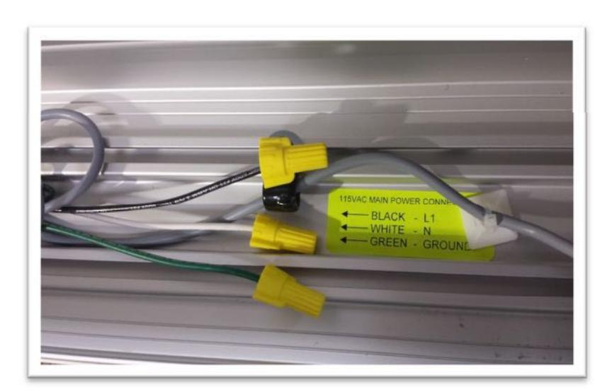
STEP 8: 120 VOLT AC ELECTRICAL CONNECTION
WARNING:
Ensure all incoming electrical power is shut off before proceeding with any high voltage wiring. Failure to do so may result in damage to equipment or personal harm.
-
Connect the main power to the Black / White / Green connector on the back-plate.
- o Main power supply: 120 VAC, 15A, Single Phase, 60 Hz. circuit
- o Attach the incoming 120 volt AC line wires to the wiring provided in the header as shown below.
- DO NOT TURN POWER ON until all remaining wiring has been completed.
BLACK: 115 VAC Power
WHITE: Neutral GREEN: Ground

STEP 9: POWER ON & TUNE-IN
- Ensure all wiring is complete according to the application
- Ensure the 120 VAC is connected and secure
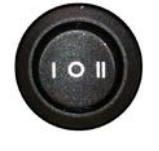
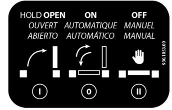
- Ensure Off-On-Hold Switch is in the middle (0) position
- Apply power and observe the LED's at the control
- The control will not accept an activation until approx. 8 seconds after powering on
- The control will not initially activate the door until an activation, such as input 10, is triggered
I/O Board LED Status
| LED | LED ON | LED OFF | NOTES |
|---|---|---|---|
| LD1 | Accessories power is present | No accessories power | |
| LD2 | Active internal opening command | Internal opening command inactive | Indicates status of input 10 |
| LD3 | Active external opening command | External opening command inactive | Indicates status of input 11 |
| LD4 | Emergency command inactive | Emergency command active | Indicates status of input 12 |
| LD5 | Secondary Activation inactive | Secondary Activation command | Indicates status of input 13 |
| active | |||
| LD6 | Stop command inactive | Stop command active | Indicates status of input 14 |
| LD7 | In active | Inactive | Inactive |
| LD8 | Fire Alarm command is active | Fire Alarm command inactive | Indicates status of input 16 |
| LD9 | Overhead Presence Command | Overhead Presence Command | Indicates status of input 17 |
| Active | Inactive |
-
As a general rule for LED observation:
- o For normally open inputs, the respective LED will illuminate upon triggering the input.
- o For normally closed inputs, the respective LED will extinguish upon triggering the input.
- o This information can be used to help quickly troubleshoot and find triggered circuits.
STEP 9 Cont.: POWER ON & TUNE-IN
-
Perform a setup at the control as follows:
- o Ensure main power is on
- o At the I/O control board, depress the SW1 button for approximately 5 seconds. When the red LED (LD2) at the Adjustment Board begins flashing rapidly, release the button.
- o Door will slowly go open, recycle partially, close and then re-open.
- o Do not interrupt the process and do not move the door manually during this time.
- o If the door does not open and the red LED (LD2) is flashing slowly, check to make sure the motor is plugged in properly at the control board. Correct as necessary.
- o Once the setup process is complete, the door will close and the LED will go out.
- o Setup is complete.
IMPORTANT NOTE: If the operator stroke is altered in any way, a re-learn must be accomplished.
- Upon completion of the Setup, activate the door to open and ensure all performance is acceptable.
- Adjust opening and closing speed as necessary. If speeds are changed, a re-learn is not required.
- A re-learn is not required following a main power recovery.
- Adjust hold-open time as required.
SETUP BUTTON
FLASHING RED LED
TROUBLESHOOTING
| Door will not open |
•
Check On-Off switch for proper position • Check LED status for LD 5, 6, and 7. If any of these LED's are OFF, the door will not open. They require a normally closed circuit. • Launch a new setup – see page 28 • Check status of emergency input 12 • Door has traveled close past the 0 degree position |
||
|---|---|---|---|
|
Door will not close
Door will not reach its full open or closed position |
•
Check status of LEDs" LD2, 3, 4, 8 on the I/O board. • If any of the LED's are ON, check the associated input • Check the mechanical stops on the operator for proper adjustment (see page 16) |
||
|
Slow flashing red LED (LD2) at the
Adjustment Control Board |
•
Indicates a possible fault in the control. o Check LED status for the other inputs. This will identify if any inputs are currently active. • Indicates a potential faulty setup. o Loose or incorrect motor connection o Possible loose chain tensioner - refer to Appendix for chain tensioner adjustment procedures. o Launch a new setup. If problem repeats and there are no other discrepancies noted, replace the operator/control sub assembly. |
||
|
Door closes too fast at last 5 to 10
degrees of closing |
•
Ensure dip switch 8 is OFF. • Ensure there is no binding of the door as it is closing through the last few degrees of closing. If binding exists (from a tight bottom sweep, for example), correct the condition and then re-launch a new setup. |
||
APPENDIX – CHAIN TENSIONER ADJUSTMENT
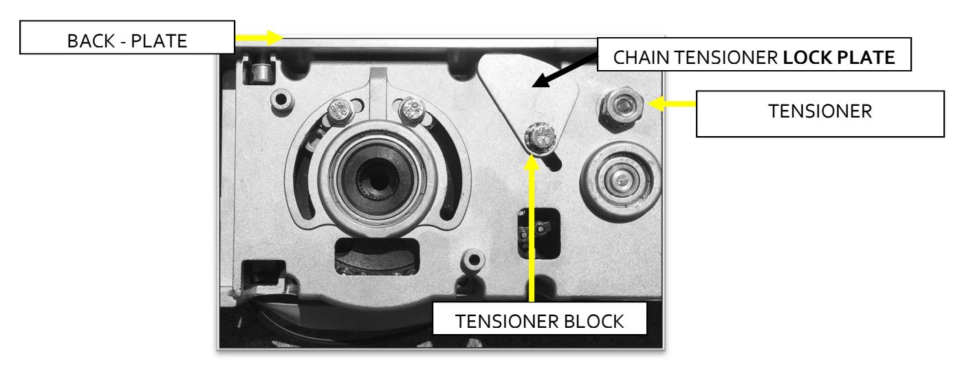
SIGNS OF A LOOSE CHAIN TENSIONER
- Opening or Closing door movements may be erratic
- The door may reverse open on its own during the closing cycle
- When a setup is launched, the door may appear to open a few degrees at a time, especially as it is just beginning to open
- Door may not open to its full open position it may stop short and then close, as it thinks there was an obstruction
- Operator may make a loud clicking noise this is created by the chain jumping on the sprockets
- There may be a "lag" between operator movement and door movement this is due to the chain "slack" being taken up before door movement
- Door may go through a setup correctly but then will show a flashing red error LED upon completion of setup, or upon the first attempt to open
- If chain is excessively loose, it is possible for the chain to become bound up on itself, thus preventing automatic door movement - this will usually happen on the closing stroke
- Abnormal noises may come from the operator as you use the door manually
- Wear marks may be evident on the body of the operator where the tensioner bolt has slipped
ADJUSTING THE CHAIN TENSIONER
- 1. At the tensioner pivot point, loosen the lock nut at the Tensioner Adjustment.
- 2. At tensioner block, loosen the Allen-head screw (do not remove it).
- 3. Insert 4mm Allen wrench into the tensioner adjustment and apply tension counter clockwise to increase tension on the chain.
- 4. Rotate chain tensioner lock plate clockwise so the plate is pressing against the back plate
- 5. Re-torque the tensioner block screw while maintaining chain tension These bolts are generally torqued to around 3.7ft lbs.
- 6. Re-tighten the lock nut at the pivot point.
- 7. When complete, double check physical stops for 0 and 90 degree door position adjust if necessary.
- 8. Launch a new setup at the control and ensure everything works ok. Any time the stroke of the operator has changed, a new setup will be required.
APPENDIX – WIRING DIAGRAMS
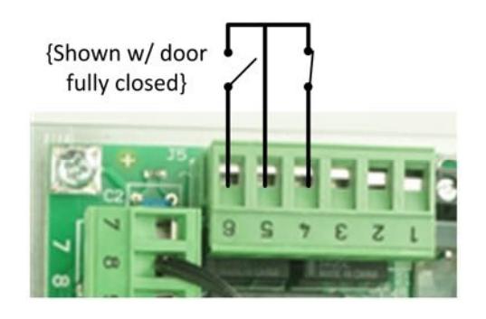
DOOR STATUS SWITCH OUTPUT
Terminal 4 : Door "Closed" status switch: Contact closes upon full door closed position.
Terminal 5 : Common for both Door Open & Closed status
Terminal 6 : Door "Open" status switch: Contact is closed when door is full open.

LOW ENERGY APPLICATION 1: PUSH PLATES WITH APPROACH SIDE DOOR-MOUNTED SENSOR
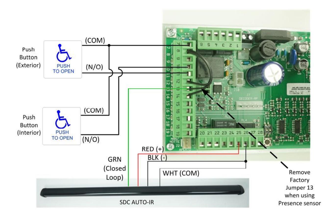
- Non-Swing Side (approach) door-mounted sensor is wired into the secondary activation input (13) at the I/O board. It is a normally closed circuit. Remove factory jumper on terminal 13.
- Door-mounted sensor will cause re-activation when in detection during the closing cycle.
- Secondary activation input is disabled at the full closed door position.
- Jumpers must be installed between terminal 8 and 12 & 14 if those inputs are not required for the application. If they are used for the application, they must be connected to a N.C. circuit.

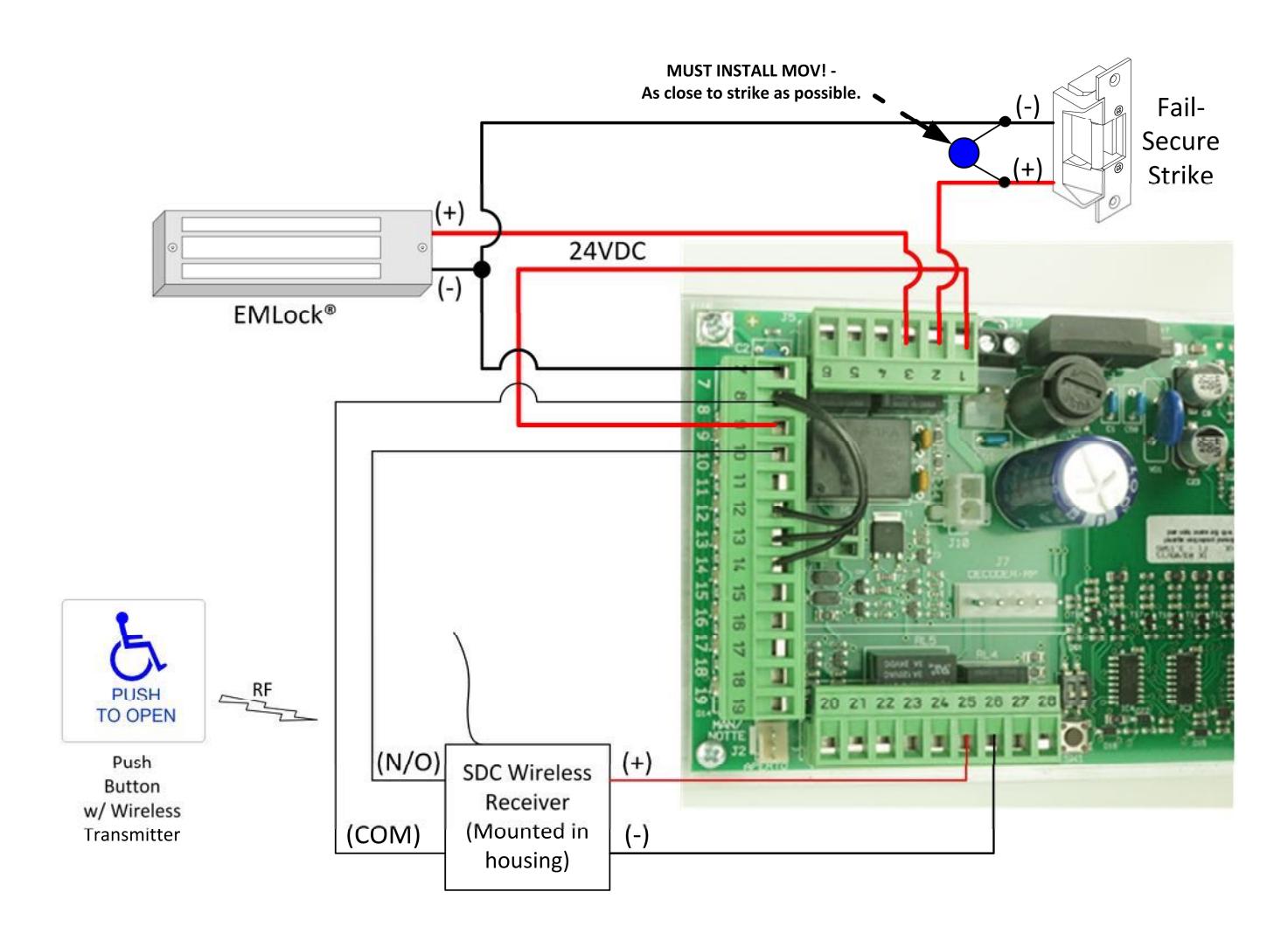
LOW ENERGY APPLICATION 2: WIRELESS PUSH PLATE WITH 24VDC ELECTRIC STRIKE OR MAGLOCK

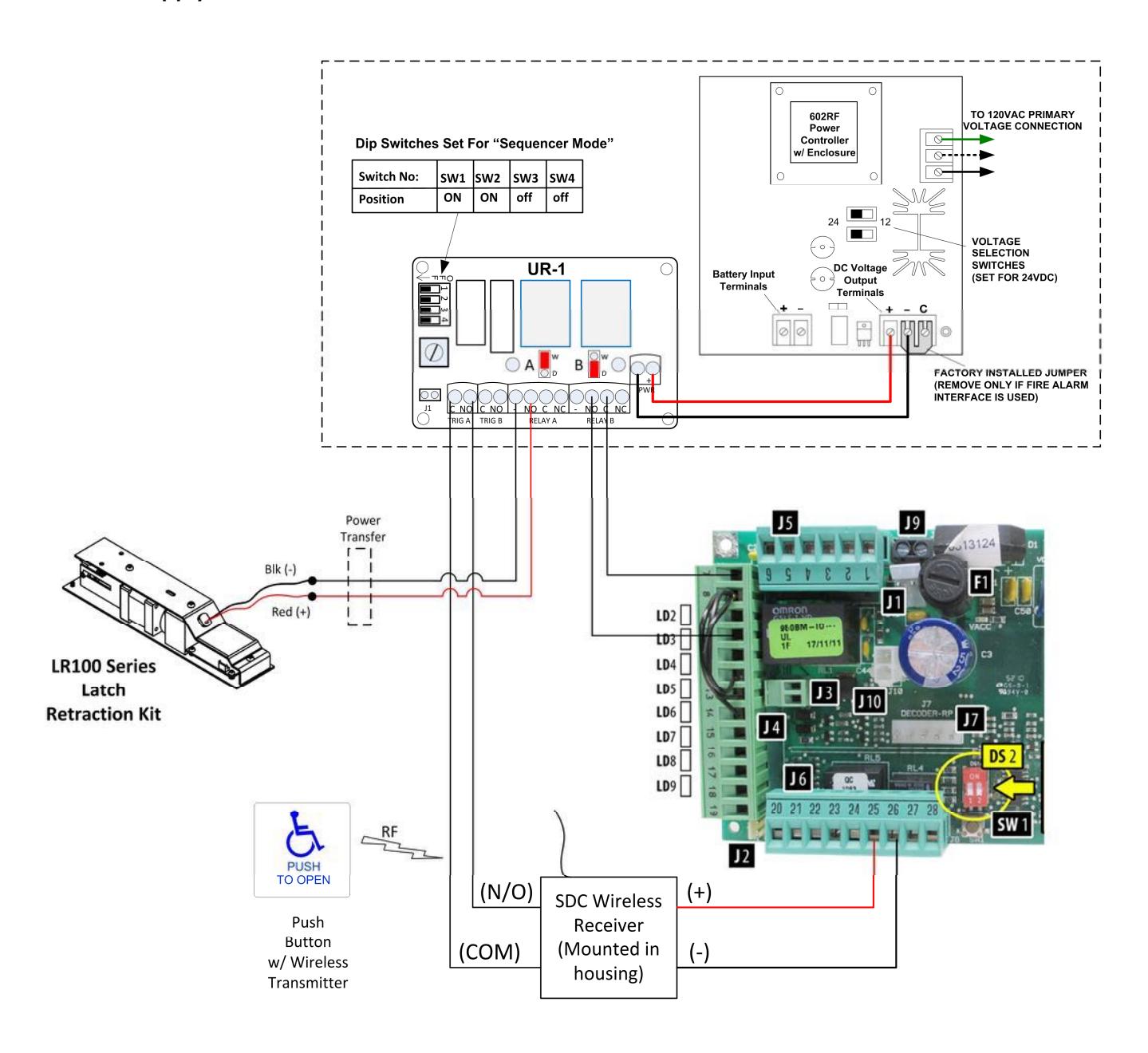
LOW ENERGY APPLICATION 3: WIRELESS PUSH PLATE WITH SDC Electric Latch Retraction Kit & Separate SDC Power Supply
LOW ENERGY APPLICATION 4: SIMULTANEOUS PAIRS
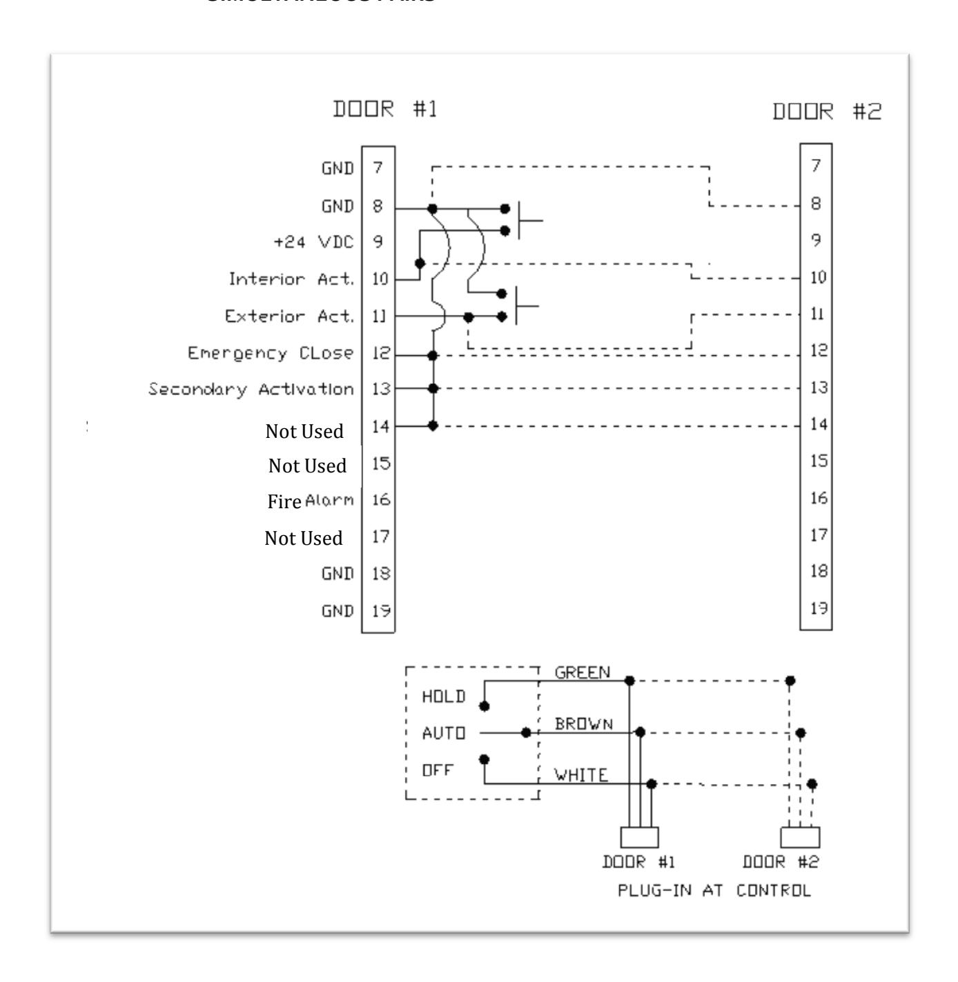

- When wiring controls for use as a simultaneous pair, all required inputs need to be synchronized (connected) between Door #1 and Door #2 (shown as dotted lines in above diagram).
- Example shown above: Push plates are connected to inputs 8, 10 and 11 at door #1 and are connected via sync line to Door #2.
- When using pairs of controls, N.C. inputs 12, 13 and 14 may be sync'd to each other, OR each control may have its own jumpers installed. If any of these inputs are required for the application, the jumper will be removed for the respective input – in place of the jumper, a N.C. switching circuit will connected to Door #1, and a sync line will be connected to Door #2.
- For simultaneous pairs, each plug-in connector for the control is wired in parallel to the On-Off-Hold switch located in the header end-cap. One switch will control both doors.
- All control adjustments (speed & time delay) must be made independently at each control.
- All dip switches at each control must be set independently and must match between controls.

APPENDIX- LOCK RELAY FUNCTION
|
AUTO
OFF-HOLD SELECTOR SWITCH STATUS |
DIP
SWITCH 3 |
INPUT
10 |
INPUT
11 |
LOCK RELAY
STATUS (door closed) |
OPERATION | REMARKS | |
|---|---|---|---|---|---|---|---|
| Line 1 | AUTO | OFF | Active | Active | DE-Energized |
Upon activation (10 or
11), lock relay energizes and door opens |
This is typically the
desired operation. If it is necessary to shut off all activation when selector switch is OFF AND keep door locked, place dip switch 3 ON and see Note #3. |
| Line 2 | OFF | OFF | Inactive | Inactive | Energized |
Placing the selector
switch to OFF unlocks the door and remains unlocked. All activation is disabled. |
Not typical for US
market. |
| Line 3 | OFF | ON | Active | Inactive | DE-Energized |
Upon activation (10),
lock relay energizes and door opens. This serves as an "Exit Only" function. Input 11 is disabled. |
Typical for exit only |
| Line 4 | AUTO | ON | Active | Active | DE-Energized |
Upon activation (10 or
11), lock relay energizes and door opens. |
Typical for 2-way traffic |
NOTE 1 : The most common setup is Line 3 & 4(above). In this setup, input 11 is disabled when the selector switch is in the OFF position.
NOTE 2 : Regardless of lock setup, Input 13 (secondary activation) functions normally and will shut off at closed-door position.
NOTE 3 : If it is desired to keep door locked AND shut off ALL activation when selector switch is OFF, place dip switch 3 ON AND tie all activation into Input 11.
NOTE 4 : Only electric strikes that are DC operated should be used. AC strikes that buzz will maintain the buzzing noise until door gets fully closed again. The lock voltage is applied at activation and not released until the next closed door position.
NOTE 5 : When selector switch is placed in Hold-Open position, lock relay remains energized.
APPENDIX- FIRE RATED DOOR APPLICATION
-
Perform the installation according to the instructions outlined in this manual. Additionally, ensure the following conditions have been met:
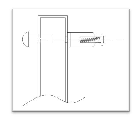
- o When attaching the door arm to the door, use steel binding posts (Sex Bolts) to attach. Do NOT use sheet metal screws into the face of the door. The door arm bracket must be through-bolted.
o When attaching the header to the hollow metal door frame, ensure there are 5 attaching screws spaced equally apart. They should be #12 sheet metal type screws.


-
Fire rated power operated doors must close and latch during a fire alarm condition. Ensure proper procedures have been followed to allow a main power disconnect during a fire alarm condition. Always check to ensure compliance to local building codes.
- o Upon job completion, always perform a functional test to ensure that the door(s) close and latch following a power loss.
- Other hardware may be required to complete the installation. For example, for pairs of doors, if an Astragal is installed, a mechanical door coordinator may be required to ensure a proper coordinated closing during a power loss.
- Only fire rated hardware shall be used on a fire rated door & frame assembly.
- Ensure the Auto EntryControl™ operator that is being installed has the proper fire rated label applied to the header.