Auto Entry Installation Instructions For Door Mounted Presence Sensor
Open the original PDF document
View PDF

Auto-IR36/48 – Door Mounted Presence Sensor
INSTALLATION GUIDE

The AUTO-IR is an active infrared sensor primarily used as a reactivation sensor for low energy automatic swing doors. Mounted on the approach side of the door, the Auto-IR will reactivate or hold the door open upon detection. The Auto-IR is mounted out of harm's way at the top of the door, eliminating damage caused by shopping carts or hospital gurneys. The perfect solution for additional safety and energy cost savings for low energy automatic doors.
|
Product Part Number
Auto-IR36 35", Black (Including End Caps) Auto-IR48 47", Black (Including End Caps; may be cut down) Technology Active infrared (wavelength 880nm); Triangulation principle IR Spot Dimension Approx. 3" (75 mm) in diameter at mounting height of 7' Power Consumption 110mA (max.) Wiring 8' Pigtail Scanning Range Setting Via adjustment wheel screw Black/White Difference Max: 20% (With reference to scanning range set) White: longer scanning range Black: shorter scanning range Response Time Upon Detection Approx. 30 ms Operating Voltage 17…30 VDC Relay Output Contact Rating: 1A at 24 VDC - Resistive Mounting Height 6' to 9' Protection Class NEMA 5 (IP52) in housing with aluminum rail, cover and end caps |
Description | Specification |
|---|---|---|
| Material | Mounting Rail: Aluminum ; Lens cover: Polycarbonate (black); End caps: ABS | |
|
Operating Temperature
-4°F to +140°F (-20°C to +60°C) |
||
|
Dimensions (Sensor only)
L x W x H (without housing) 10" x 1 ¼" x 1" |
||
|
Dimensions (Housing including end caps)
L x W X H (length variable) x 1 ½" x 1 ¾" |
||
|
Weight
With 36" assembly: 1 lbs, 8 oz (0.68 kg) |
||
|
Sensor only:
1.6 oz (45 g) |

IMPORTANT
READ THIS SECTION BEFORE PROCEEDING WITH INSTALLATION
INSTALLATION PRECAUTIONS
Security Door Controls (SDC) recommends that all of its automated pedestrian door products be installed by a trained automatic door technician and that the resulting performance of the product be in full compliance with the most current version of the American National Standards Institute document A156.19 as well as any applicable building codes and/or fire codes. SDC further recommends that a full inspection of the operating system be performed in accordance with the guidelines of the American Association of Automatic Door manufacturers (AAADM). This inspection must be performed by a certified AAADM trained inspector . SDC recommends this documented inspection be performed upon completion of the installation as well as, following the completion of every service call thereafter. If service is not performed within one year of the previous service action, a routine AAADM inspection should be performed and documented. Under no circumstance should the product operate for more than one year without an AAADM inspection. SDC does NOT recommend installation or service, on any of their automated pedestrian door products, by any individual who is not certified as an AAADM inspector. Following the installation or service of any SDC automated pedestrian door product, if it is deemed unsafe, or is operating in an unsatisfactory manner according to national performance standards or recommended performance guidelines as defined by SDC, repairs should be made immediately. If an immediate repair cannot be made, the product should be disabled, and appropriate measures should be taken to secure the door in a safe position or to enable the door to safely be used manually. During this situation, every effort should be made to notify the owner (or person responsible) of the condition and to advise on corrective actions that must be taken to return the product to safe operation.
PARTS LIST

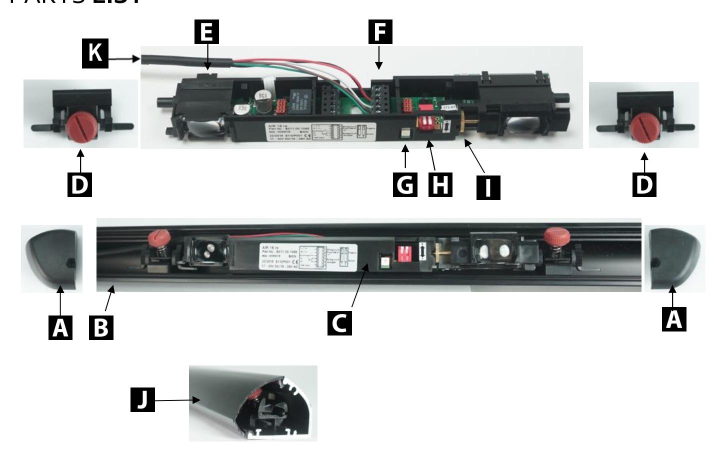
- D. Pivot end blocks (x2) K. Wiring Pigtail
-
A.
Lt/Rt End caps and screw
E.
Left/right pattern selector
H.
Dip switches
- C. Sensor assembly G. Detection indicator (LED red) J. Lens Cover
-
B.
Aluminum rail
F.
Wiring terminal block
I.
Height adjustment wheel screw
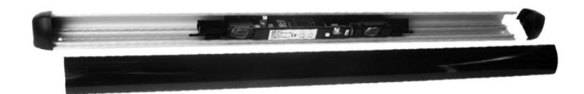
MOUNTING HOUSING RAIL
- 1. Remove the end caps & lens cover.
- 2 . Center the aluminum rail between door jambs or hinge. Place about 1" from the top of the door or arm fixture/slide rail (if applicable).
- 3. Attach the aluminum rail to door panel with self-drilling screws (included).
Self-drilling screws (x2)

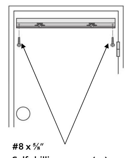
SELECTING THE DETECTION AREA
Depending on the door opening, a right or left sensing location must be selected.
First, the sensor assembly must be moved to the appropriate end of the rail.
Second, the R</>L selector must be set, as shown below. The selector can be found on the backside of the optics.
Refer to Page 7 for instruction on repositioning and/or removing the sensor assembly.
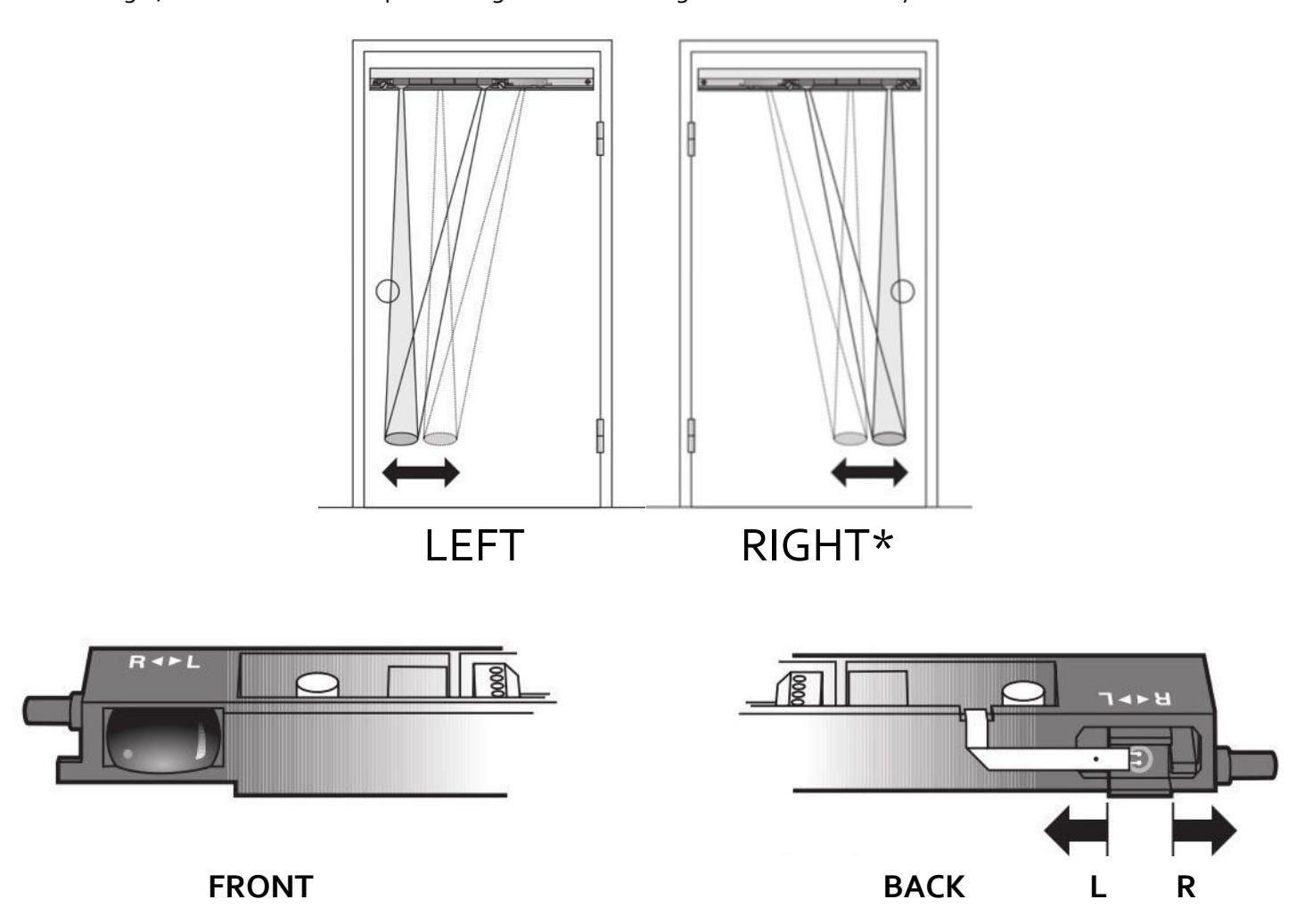
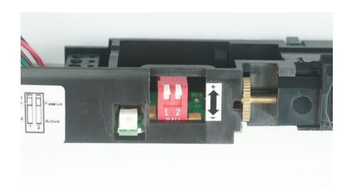
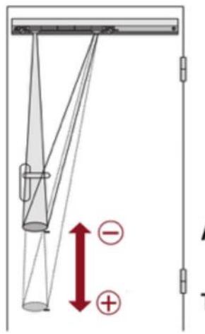
To change the detection area, slide the plastic selector to positon L or R* . *Factory Setting Position of the detection area L = Left R = Right

ATTENTION: Recommended trigger point should never be greater than 7-8" above the floor surface.

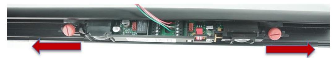
REPOSITIONING AND/OR REMOVING THE SENSOR ASSEMBLY
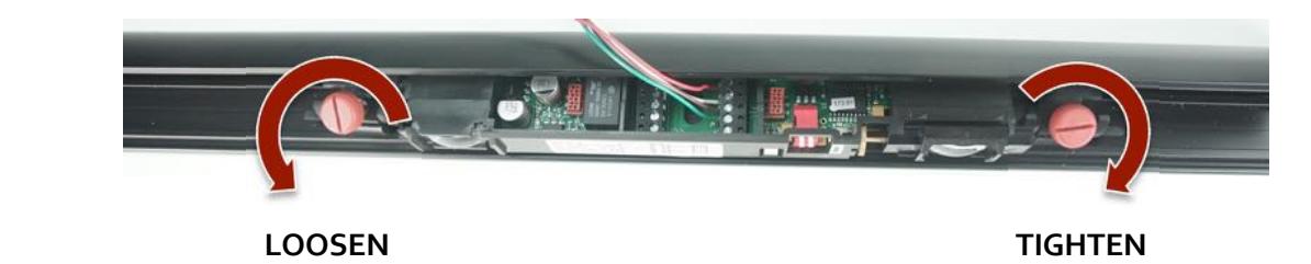
Use the screw knob to loosen (unlock) or tighten (lock) the pivot end blocks (2 x - left side and right side)
To reposition the sensor (left or right), unlock both pivot end blocks and slide the entire assembly until the end block is about 1"-2" from the end of the rail. (Right side shown)
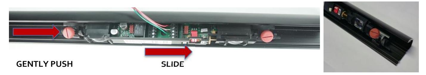
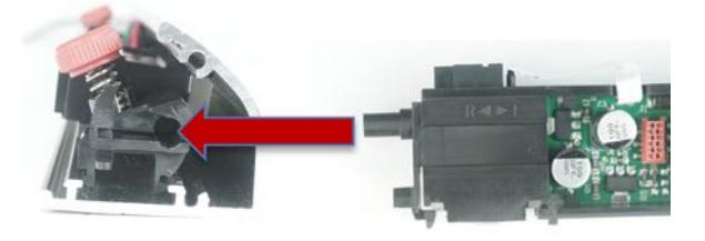
To access the back of the optics, and to change the Left/Right selector.
Loosen both pivot blocks, and slide them away from the sensor optics. Gently pull the sensor from the rail, and adjust the selector to R or L, as shown on Page 5.

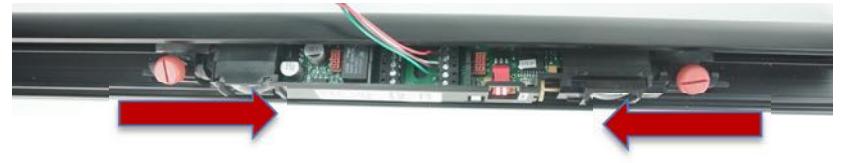
After setting the selector switch, re-install the sensor by re-inserting both pivot end blocks, and tighten.
IMPORTANT: When re-installing the sensor, make sure that the wiring pigtail is routed behind the sensor.

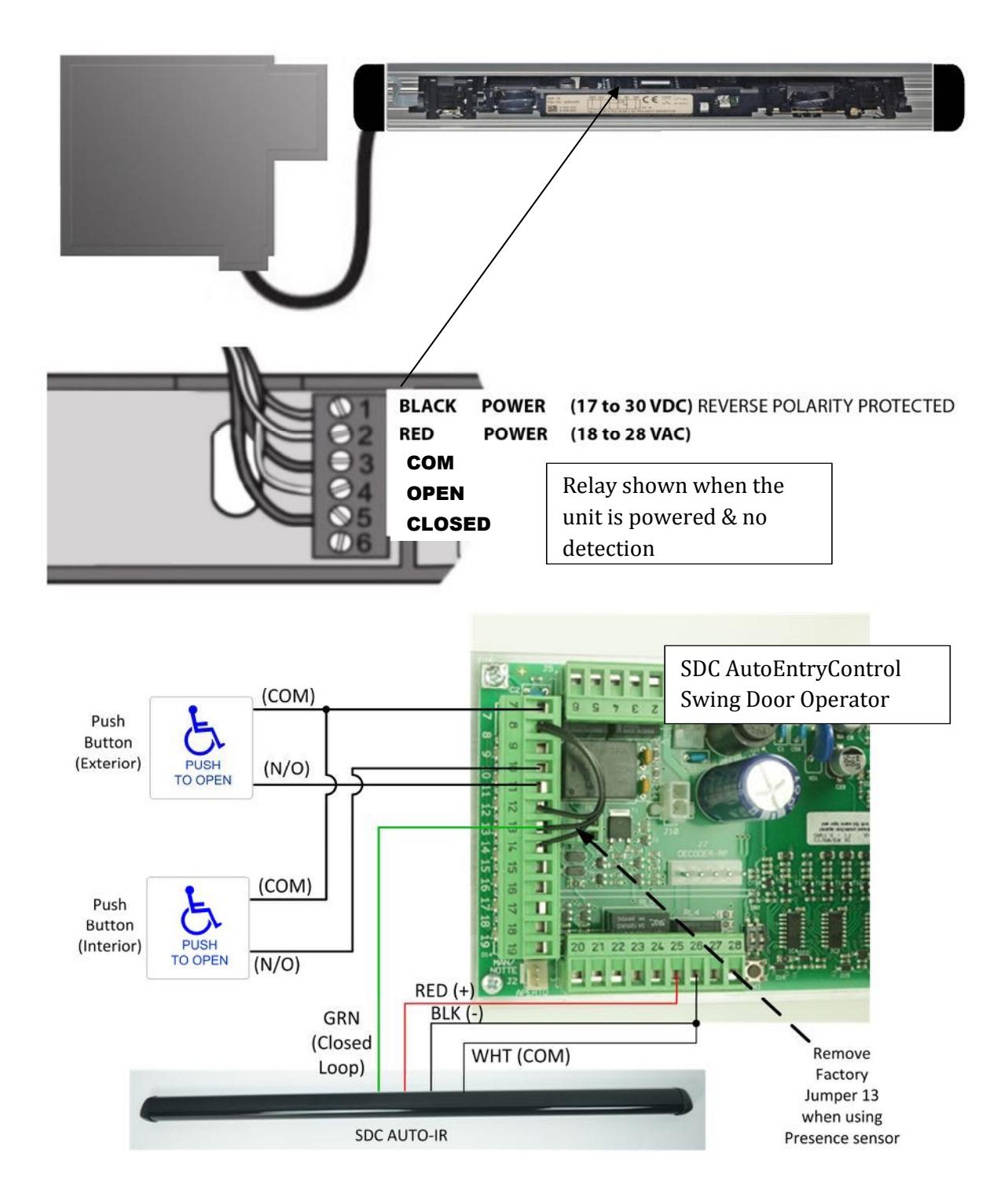
WIRE THE SENSOR
The AUTO-IR provides a dry relay output and can be connected directly to the activation circuit of the automatic door control. Route the sensor's cable through the cable exit in the end cap.
Route cable to the door operator (e.g. through supplied cable loop and frame end cap). Alternatively, the cable may concealed through the door, and installed in conjunction with a power transfer device.

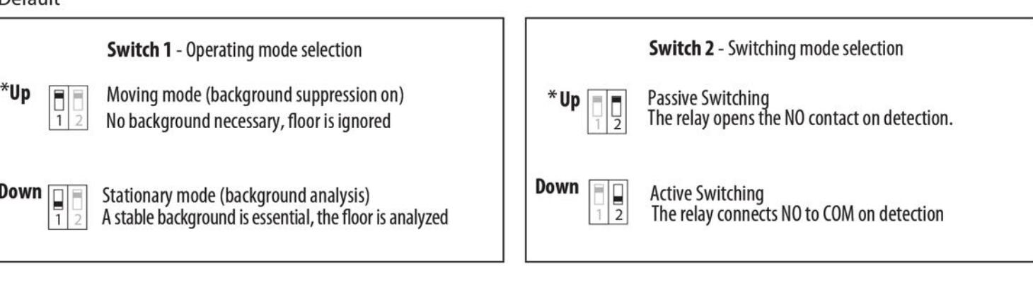
DIP SWITCH FUNCTIONS
Power the sensor after installation is complete. The LED illuminates when the sensor detects a presence.
NOTE: The default settings will be satisfactory for most installations.
OPERATION SELECTION Switch 1 = Detection Mode UP = OFF | DOWN = ON Switch 2 = Relay Mode
- 1. First, check trigger point with a white letter size sheet of paper. Then use a screwdriver to adjust scanning range on sets crew.
- 2. If needed, adjust the tilt angle (see Page 10) or adjust the detection area by sliding the sensor in the rail (see Page 7)

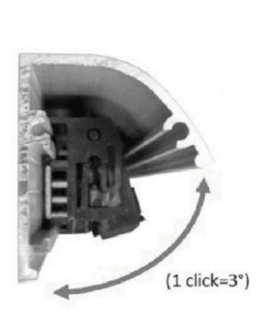
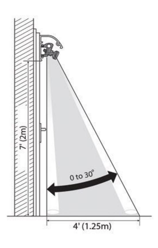
TILT ANGLE ADJUSTMENT
1. Using both hands, grasp both sides of sensor and carefully tilt up or down to change the inclination angle.
The angle 0° to 30° can be read on the sides of the mounting brackets.
2. Ensure sensor is level by setting the same angle on both brackets. (1 click = 3°)

CLOSING HOUSING
- 1. Click plastic lens cover to aluminum housing.
- 2. Attach end caps using screws provided.
- 3. Remove blue plastic protective film from lens.
- 4. Ensure it is secure along the entire length of rail.
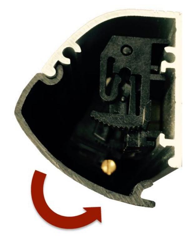
INSERT TOP OF LENS COVER AND PUSH IN TO CLOSE