Auto Entry Installation Instructions For AUTO-PROG
Open the original PDF document
View PDF

801 Avenida Acaso, Camarillo, Ca. 93012 • (805) 494-0622 www.sdcsecurity.com • E-mail: service@sdcsecurity.com
PROGRAMMING MANUAL AUTO-PROG ADVANCED PROGRAMMER FOR AUTO ENTRYCONTROL OPERATORS
| 1. AUTO-PROG |
|---|
| 1.1 Installation and connections |
| 1.2 Switching on and the home screen4 |
| 1.3 SELECTION menu |
| 1.4 FUNCTIONS menu |
| Table A. AUTO-PROG Functions Menu |
| 1.5 PROGRAMMING menu descriptions10 |
| Table B. Access permissions and passwords 13 |
| 2. DIACNOSTICS |
| 2. DIAGNOSTICS |
| Table C. I/O board LEDs 14 |
| Table D. Logic board LEDs 14 |
| Tuble D. Logic board LEDS14 |
| 2.2 Inputs and outputs status check |
| 2.3 Automation status check |
| Table E. Door Status |
| 2.4 Warnings |
| Table F. Warnings |
| 740/6 7. Wallings |
| 2.5 Errors |
| Table G. Errors |
| 2.6 Other board data |
| 2.7 Firmware versions |
| 2.8 Log Data |
| 3. NETWORKING MULTIPLE OPERATORS |
| 3.1 Intermode |
| 3.2 Interlock |
| Interlock with no memory |
| Interlock with memory |
| 3.3 Pair of Doors |
| 3.4 Interlocked Pairs of Doors |
| 4. OPERATOR MAINTENANCE |
| 4.1 Inserting / replacing the battery |
| 4.2 Replacing the fuse |
| 4.3 Routine maintenance |
1. AUTO-PROG
1.1 INSTALLATION AND CONNECTIONS

CARRY OUT THE FOLLOWING OPERATIONS WITH THE POWER SUPPLY DISCONNECTED
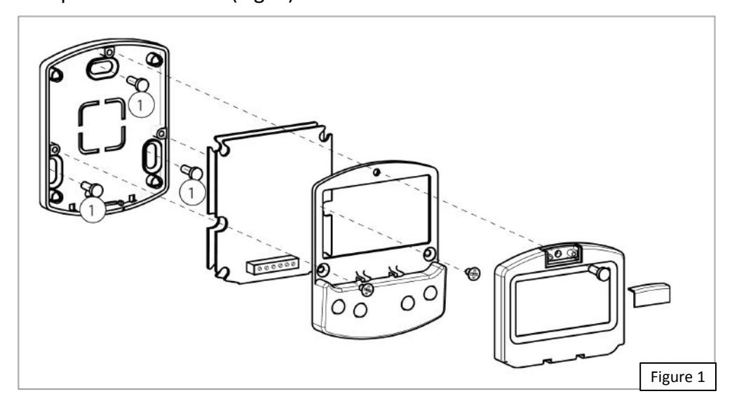
- 1. Disassemble the parts (Fig. 1).
- 2. Break the cable passage insert as needed.
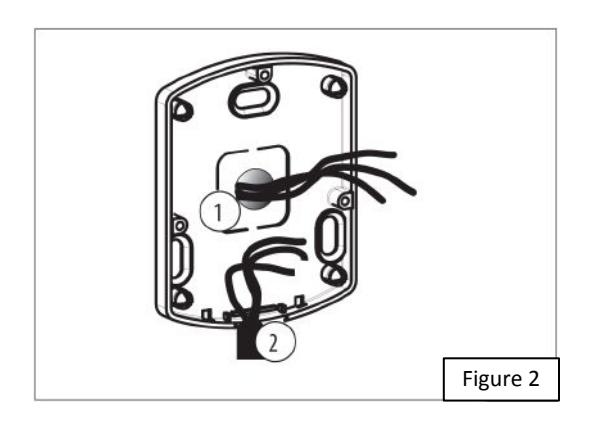
- Referencing Fig.2, the AUTO-PROG is designed for the cables to enter from the back (1) or from underneath (2).
- 3. The AUTO-PROG may be used as a handheld device or fixed to a surface. If a fixed location is desired, determine the position and attach it using the slotted mounting holes & suitable screws (Fig. 1 (1)).
-
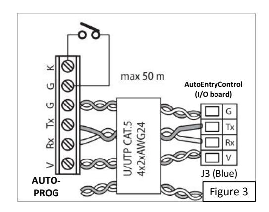
4. Connect the AUTO-PROG to the AutoEntryControl I/O board using a 4 pair twisted U/UTP AWG24 cable with a maximum length of 164 feet (Fig. 3). Be careful to observe polarity!
- An optional key switch device may be connected between terminals G and K in order to enable/disable the AUTO-PROG.
- 5. Reassemble the parts indicated in (Fig. 1).
1.2 SWITCHING ON AND THE HOME SCREEN
- 1. Turn power on to the AutoEntryControl
- 2. The display will momentarily show the following in sequence:

in which the Bootloader version appears, then
in which the firmware version appears, and lastly
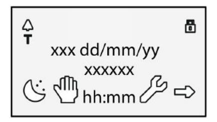
The content of this home screen is explained below in Figure 4 below.
- 3. The 4 buttons are used to select controls that, depending on the screen, appear on the display above them.
- 4. By pressing the relative button on the home screen (Fig. 4) you can:
- = set the NIGHT mode
- = set the MANUAL mode
- = switch to the FUNCTIONS menu that includes all the AutoEntryControl conguration parameters.
- = switch to the SELECTION menu that includes additional operating modes.

By pressing the button to set the NIGHT or MANUAL mode, the relative icon is highlighted and the description of the operating mode is updated on the display. Once NIGHT or MANUAL mode has been set by pressing the respective button, press it again to return to the previous mode.
1.3 SELECTION MENU
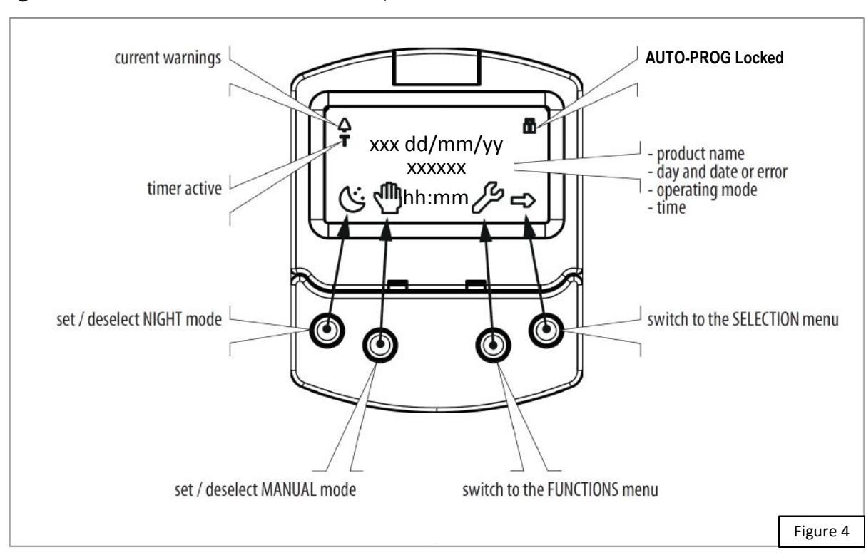
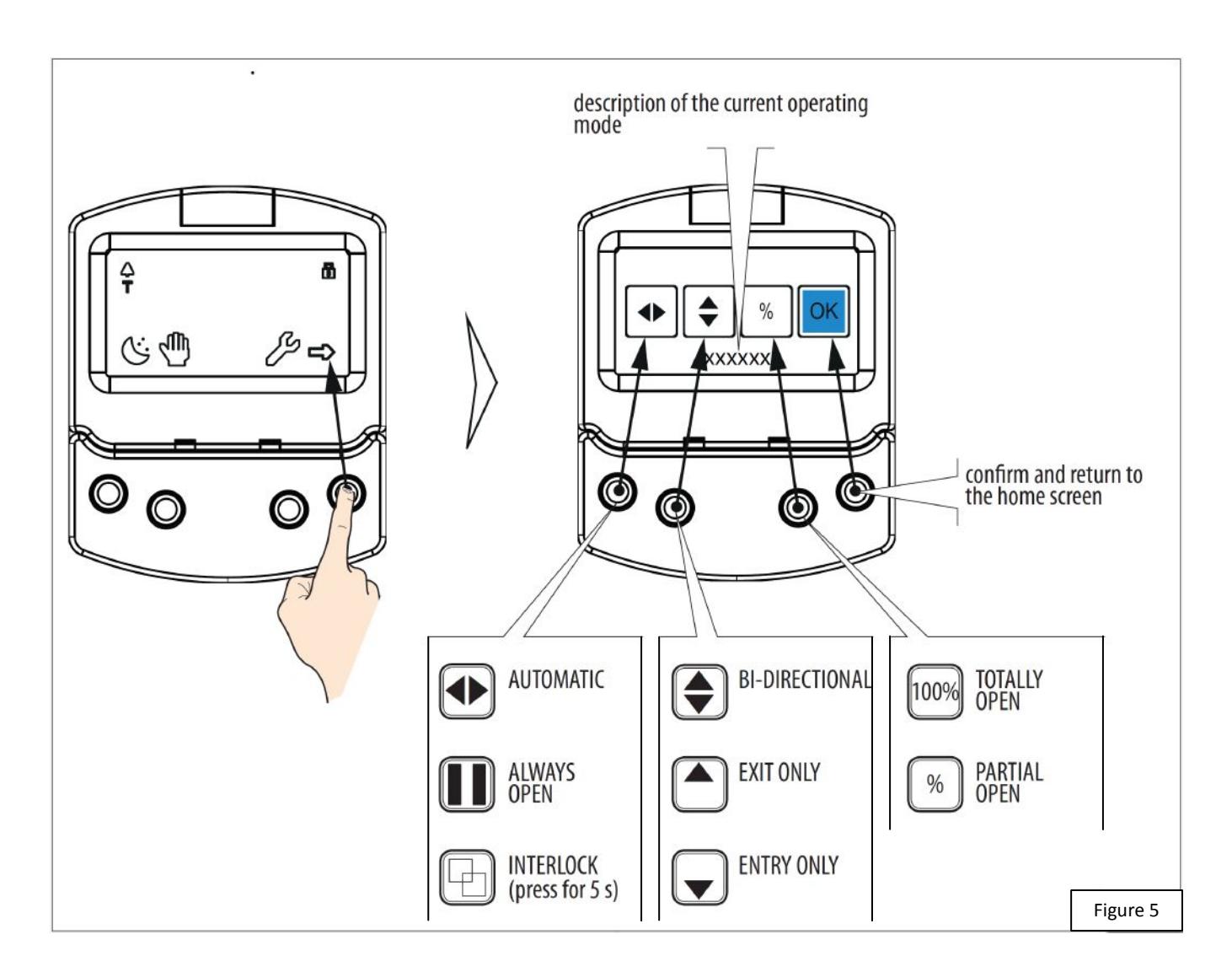
To access the SELECTION menu from the home screen, press the button (Fig. 5).
Four new icons appear on the display that define the operating modes that can be set. The possible combinations can be obtained by pressing the corresponding buttons (Fig. 5). After having set the operating mode, press the OK button to confirm and return to the home screen.
The description of the operating mode on the display is updated with the description of the one that has been set in the selection menu.
1.4 FUNCTIONS MENU
To access the FUNCTIONS menu from the home screen, press the button (Fig. 6).
The display prompts for a 4-digit password to be entered.

The factory-set password is: 0000
- Set the first pw digit using the and buttons.
- Confirm using the OK button to move to the next digit.
- When all 4 digits have been entered, if the password is correct, access the FUNCTIONS menu on the right.
- Select the item from the menu using the and buttons.
- Confirm using the OK button to enter.

Press ESC at any time to return to the home screen.
All the possible menu functions are shown on the next few pages (see Table A). A description of each menu option is detailed following Table A, in Section 1.5.
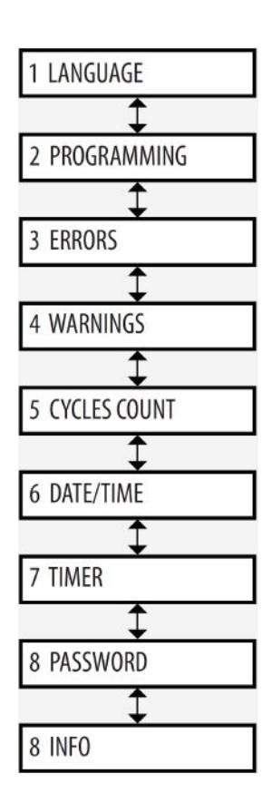
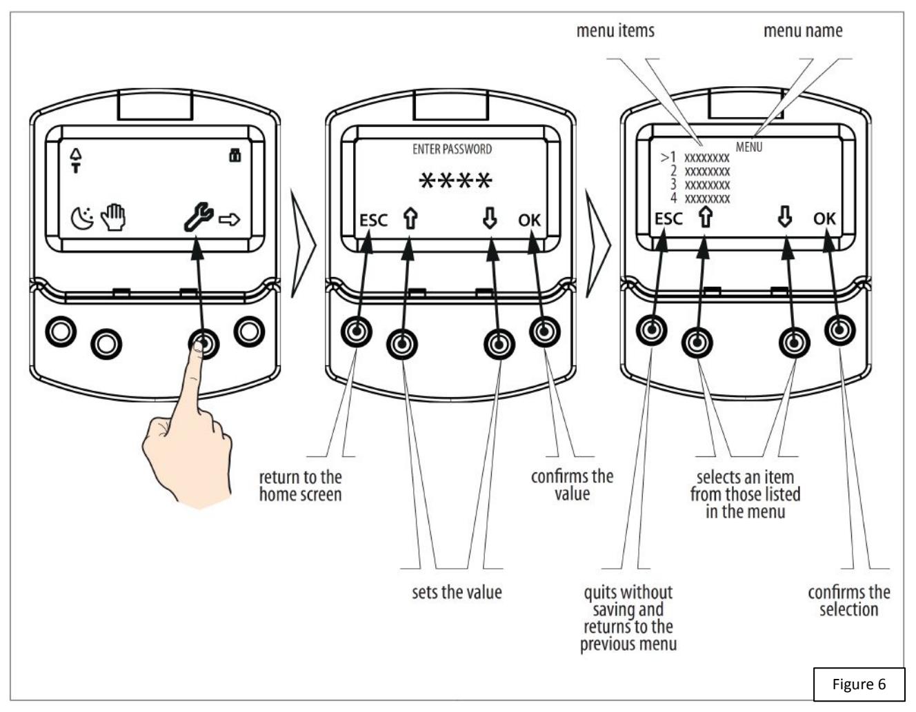
TABLE A.
               AUTO-PROG FUNCTIONS Menu
1 LANGUAGE
     1 ITALIANO
     2 ENGLISH
     3 FRANCAIS
     4 DEUTSCH
     5 ESPANOL
     6 NEDERLANDS
2 PROGRAMMING
     1 INPUTS / OUTPUTS
          1 INPUTS I1-I8
                    11...18
                         0 DISABLED
                         1 EXTERNAL OPEN
                                                        NORMALLY OPENED / NORMALLY CLOSED
                         4 INTERNAL OPEN
                                                        NORMALLY OPENED / NORMALLY CLOSED
                         7 AUTOMATIC OPEN
                                                        NORMALLY OPENED / NORMALLY CLOSED
                         8 SEMIAUTOM. OPEN
                                                        NORMALLY OPENED / NORMALLY CLOSED
                         10 KEY
                                                        NORMALLY OPENED / NORMALLY CLOSED
                         11 PARTIAL OPEN
                                                        NORMALLY OPENED / NORMALLY CLOSED
                                                        NORMALLY OPENED / NORMALLY CLOSED TEST ENABLED / DISABLED
                         20 CLOSING SAFETY
                                                        NORMALLY OPENED / NORMALLY CLOSED TEST ENABLED / DISABLED
                         21 OPENING SAFETY
                         22 OVERHEAD PRES. SENS
                                                        NORMALLY OPENED / NORMALLY CLOSED
                         30 EMERGENCY OPEN
                                                        NORMALLY OPENED / NORMALLY CLOSED
                         31 EMERGENCY OPEN WITH MEM
                                                        NORMALLY OPENED / NORMALLY CLOSED
                         34 EMERGENCY CLOSE
                                                        NORMALLY OPENED / NORMALLY CLOSED
                         35 EMERGENCY CLOSE WITH MEM
                                                        NORMALLY OPENED / NORMALLY CLOSED
                         36 FIRE ALARM
                                                        NORMALLY OPENED / NORMALLY CLOSED
                         40 ALWAYS OPEN
                                                        NORMALLY OPENED / NORMALLY CLOSED
                         41 EXIT ONLY
                                                        NORMALLY OPENED / NORMALLY CLOSED
                         42 ONLY IN
                                                        NORMALLY OPENED / NORMALLY CLOSED
                         43 NIGHT
                                                        NORMALLY OPENED / NORMALLY CLOSED
                         44 MANUAL
                                                        NORMALLY OPENED / NORMALLY CLOSED
                                                        NORMALLY OPENED / NORMALLY CLOSED
                         45 PARTIAL
                         46 INTERBLOCK ON
                                                        NORMALLY OPENED / NORMALLY CLOSED
          2 OUTPUTS 01/02 60 TIMER
                    01...02
                         0 DISABLED
                         1 GONG
                                                        NORMALLY OPENED / NORMALLY CLOSED
                         2 ERROR
                                                        NORMALLY OPENED / NORMALLY CLOSED
                         4 EMERGENCY ACTIVATE
                                                        NORMALLY OPENED / NORMALLY CLOSED
                                                        NORMALLY OPENED / NORMALLY CLOSED
                         5 TEST
                                                        NORMALLY OPENED / NORMALLY CLOSED
                         6 DOOR NOT CLOSED
                         7 DOOR OPENED
                                                        NORMALLY OPENED / NORMALLY CLOSED
                         8 DOOR OPENING
                                                        NORMALLY OPENED / NORMALLY CLOSED
                         9 LIGHT
                                                                                           NORMALLY OPENED / NORMALLY
                                                        TIME 1...90 S
                                                        NORMALLY OPENED / NORMALLY CLOSED CLOSED
                         10 INTRUSION ACTIVE
                                                        NORMALLY OPENED / NORMALLY CLOSED
                         11 CLOSING SAFETY
                         12 SAFETIES
                                                        NORMALLY OPENED / NORMALLY CLOSED
          3 OP/CLRELAY
                    NORMALLY OPENED / NORMALLY CLOSED
          4 EXTERNAL SELECTOR
                    POSITION 1...POSITION 2
                         0 DISABLED
                         1 NIGHT
                         2 OPENED
                         3 EXIT ONLY
                         4 MANUAL
| FU | NCTION: 0 | NO FUNCTION | |||
| FU | NCTION: 1 | AUTO BIDIR TOTAL | |||
| FU | NCTION: 2 | AUTO OUT TOTAL | |||
| FU | NCTION: 3 | AUTO BIDIR PARTIAL | |||
| FU | NCTION: 4 | AUTO OUT PARTIAL | |||
| FU | NCTION: 5 | TOTALLY OPEN | |||
| FU | NCTION: 6 | PARTIAL OPEN | |||
| FU | NCTION: 7 | AUTO IN TOTAL | |||
| FU | NCTION: 8 | AUTO IN PARTIAL | |||
| FU | NCTION: 9 | NIGHT | |||
| FUNCTION: 10 | PARTIAL NIGHT | non oro | |||
| BEGINNIN | |||||
| o DACCIMODD | END | hh:mm | |||
| 8 PASSWORD | CLANI DOLLI | ||||
| CIAN PSW | |||||
| CHANGE TEC PSW | REINSERT TEC PSW | NEW PSW INSERTED | |||
| 2 USER PSW | |||||
| CHANGE USER PSW | REINSERT USER PSW | NEW PSW INSERTED | |||
| 9 INFO | |||||
| E950E | BOOT | VER *.* | |||
| E950E | APP | VER *.* | |||
| KP EVO | APP | VER *.* | |||
| 2.0 | |||||
1.5 PROGRAMMING menu descriptions
■ PROGRAMMING INPUTS/OUTPUTS INPUTS (I1 - I8)

Each input can be set to NC or NO according to the device connected to it.
The inputs on terminal board J5 of the I/O board can be configured with the following functions:
Disabled
No associated function.
External open
When activated, the door opens and remains open as long as the input is active. When released, the door waits for the pause time to elapse and then closes.
This has no effect in the EXIT ONLY or NIGHT modes.
Internal open
When activated, the door opens and remains open as long as the input is active. When released, the door waits for the pause time to elapse and then closes.
This has no effect in the ONLY IN or NIGHT modes.
Automatic open
When activated, the door opens and remains open as long as the input is active. When released, the door waits for the pause time to elapse and then closes.
Active in the BI-DIRECTIONAL, EXIT ONLY and ONLY IN modes. This has no effect in the NIGHT mode.
Semiautom. open
When activated:
- if the door is not already open, it opens and remains open
- if the door is already open, it closes
Active in the BI-DIRECTIONAL, EXIT ONLY and ONLY IN modes. This has no effect in the NIGHT mode.
Key
When activated, the door opens and remains open as long as the input is active. When released, the door waits for the night pause time to elapse and then closes.
Active in the BI-DIRECTIONAL, EXIT ONLY, IN ONLY and NIGHT modes.
Partial open
Only opens the master door when activated in the "2 leaves" mode.
Closing safety
When activated:
- If the door is closing, it reopens
- If the door is already open, it prevents it from closing
- If the door is opening, it has no effect
Opening safety
When activated:
- If the door is opening, it stops until it is released
- If the door is already closed, it prevents it from opening
- If the door is closing, it has no effect
Emergency open
When activated, the door opens (always total) and remains open as long as the input is active. When released, the door waits for the night pause time to elapse and then closes.
Also active in NIGHT mode.
Emergency open with memory
When activated, the door opens (always total) and remains open as long as the input is active. When released, the door remains open until it is Reset
Emergency close
When activated, the door closes and remains closed as long as the input is active. When released, the door returns to normal operation.
Emergency close with memory
When activated, the door closes and remains closed as long as the input is active. When released, the door remains closed until it is Reset
Fire alarm
When activated, the door closes, regardless of the operating mode that has been set, with the lock kept in the released position. It has priority over any commands that may be active.
Always open
When activated, the ALWAYS OPEN mode is set.
Exit only
When activated, the EXIT ONLY mode is set.
Entry only
When activated, the ONLY IN operating mode is set.
Night
When activated, the NIGHT mode is set.
Manual
When activated, the MANUAL mode is set.
Partial
When activated, the PARTIAL mode is set.
Interblock ON
When activated, the INTERLOCK mode is set.
Timer
When activated, the TIMER mode is set.
OUTPUTS (O1-O2)

Each output can be set to NC or NO according to the device connected to it.
The outputs on terminal board J5 of the I/O board can be congured with the following functions:
Disabled
No associated function.
Gong
The output is activated and deactivated at 1-second intervals when the safety devices are engaged.
Error
The output is activated if there is an error.
Emrg. active
The output is activated when an Emergency is triggered.
Test
The output commands a FAILSAFE test on the inputs that are configured as safety devices on which the option of running a TEST before movement has been enabled.
Door not closed
The output remains active until the door is closed.
Door open
The output remains active as long as the door is open.
Door opening
The output remains active as long as the door is moving.
Light
The output is activated, for a programmable length of time, when the door is open in NIGHT mode.
Intrusion active
The output is activated when an intrusion is in progress (i.e. when an unexpected movement of the door from its closed position is detected).
Closing safety
The output is activated when a closing safety device is active.
Safeties
The output is activated when a closing or opening safety device is engaged.
OP/CL RELAY
Specifies the logic of the door status relay (NC/NO).
EXTERNAL SELECTOR
Specifies the operating mode associated with positions 1 and 2 of the selector on the side of the unit.
■ PROGRAMMING MOTION
OPENING/CLOSING
Speed
Sets the speed of movement.
Slowdown
Specifies the space (in degrees of rotation of the AUTO shaft) and the deceleration speed (on 3 levels) of the door before reaching the final open / closed positions.
Strength
Specifies the maximum crushing force.
Strength duration
Specifies the maximum thrust time before an obstacle is recognized.
Acceleration
Specifies how quickly the door reaches the set opening speed when starting from stop.
Deceleration
Specifies how quickly the door stops.
■ PROGRAMMING TIMING
PAUSE TIME
Defines the pause time of the door when opened by a command, before closing automatically.
PAUSE TIME P&G
Sets the door pause time when opened by a Push & Go command, before closing automatically.
Night PAUSE TIME
Sets the door pause time when opened by a command in NIGHT mode, before closing automatically.
NIGHT SENSOR DELAY
When NIGHT mode is set, the internal detector remains active for the amount of time set in this parameter, to allow it to be opened only once. The internal detector is disabled immediately after opening and in any case upon expiry of the set delay.
■ PROGRAMMING MOTOR BLOCK KIT
FUNCTION
Specifies the operating mode in which the lock is activated.
LOCK DELAY
Specifies the opening delay time of the door to allow the lock to be released.
RELEASE TYPE
Specifies when power is disconnected from the lock after it has been mechanically released:
Opening = during the opening phase
Closed = when the door is closed again
■ PROGRAMMING INSTALLATION
ARM TYPE
Specifies the type of transmission arm installed (shoe or slide) START SETUP
Carries out a Setup cycle after confirmation.
PUSH AND GO
Sets the function that commands the automatic opening of the door after an initial manual push:
Disabled = Push & Go not enabled
Enabled = Push & Go enabled
Fast food = Push & Go enabled in "FAST FOOD" mode (manual opening, motorized closing)
PARTIAL STOP SEC.
Specifies the detection area of the safety in opening:
Disabled = obstacle detection active over the entire opening stroke
Enabled = obstacle detection NOT active in proximity to the opening stop
LEAF DELAY
Specifies the opening delay between the doors of 2 leaf models. SCP
Specifies the function that pushes the door with a greater force in the final section of the closure. It is useful to activate this function if there is high friction or if the seals are particularly rigid.

Because activating the SCP function also reduces the sensitivity of the electronic anti-crushing system in the final section of closing, DO NOT activate the SCP function in "low energy" mode.
REVERSE STROKE
Sets the function that makes the door carry out a short reverse stroke before opening to make it easier to the release the lock. 2 EASY REG.
Registration of BUS 2easy devices.
INOUT STATE
The display indicates the status (on / off) of inputs I1-I8 and outputs O1-O2 in real-time.
DOOR STATUS
The display indicates the status of the automation in real-time.
OTHER BOARD DATA
The display indicates useful diagnostics information in real-time.
■ PROGRAMMING INTERCOM
FUNCTION
Sets the operating mode.
MASTER/SLAVE NR.
Sets the network ID of the unit.
INTERCOM REG.
Registers the units of the network (to be performed only on the AUTO with ID1).
NODE LIST
Shows the ID of the units registered (on the master).
■ PROGRAMMING MISCELLANEOUS
CONFIG. DEFAULT
Shows whether the parameters have been modified, and if so, resets the factory defaults after confirmation.
BOARD'S DISPLAY
Not active.
INTRUSION
Sets the function in which the door resists attempts to open it manually.
KPEVO KEY
You can choose between:
Block = the user must enter the user password in order to access the menus that he is authorised to use.
Without user psw = the user doesn't need to enter the user password in order to access the menus that he is authorised to use.
CONSECUTIVE OBST.
Specifies the maximum number of consecutive obstacle detections in the same direction of movement, before stopping in an error condition.
TEST ERROR
Specifies the eect that the TEST will have when it detects a safety device fault:
Disabled = the door will remain stationary in an error condition Enabled = the door will continue to operate at minimum speed
■ ERRORS
In this menu, the display indicates any current errors that there may be in real time.
■ WARNINGS
In this menu, the display indicates any current alerts that there may be in real time.
■ CYCLE COUNTER
The AutoEntryControl has two counters:
- total, non-resettable
- partial, resettable
This menu allows you to view the cycles performed by the automation
and reset the partial counter.
It is also possible to set a deadline for scheduled maintenance according to:
- date (optional)
- number of cycles (from 1000 to 1000000)
Alert 60 will be displayed as soon as one of the two settings (date or number of cycles) is reached.

Logging in with the user password only allows data to be viewed.
■ DATE/TIME
This menu allows you to set or modify the date, time.

To keep the settings even if there is no mains power, which is necessary for the TIMER to work correctly, a battery must be installed on the Logic board.
■ TIMER
This menu includes all the parameters for conguring the TIMER function.
When the TIMER is enabled, the operating mode of the door during the programmed time bands is set automatically. A maximum of 6 daily time bands can be dened, and an operating mode, selected from those available, assigned to each one. Each time band has a start time and an end time. The time bands must not overlap.

When the TIMER is enabled, the T icon appears on the home screen.
To manually change the operating mode set by the TIMER, it rst has to be disabled. In order for the TIMER to work correctly, a battery must
In order to quickly program groups of days of the week with the same time bands, it is possible to simultaneously select all the days of the week (MON - SUN) and all weekdays (MON - FRI). Once the time bands that have been dened here have been confirmed using the APPLY option, they will overwrite any time bands that have already been programmed for individual days. If it is necessary to program specic days or periods (e.g. recurring holidays), you may use the JOLLY function. A maximum of 6 JOLLY time bands can be specied and an operating mode, selected from those available, assigned to each one. Each time band has a start time and an end time. The time bands must not overlap.
be installed on the Logic board.
The JOLLY time bands are then assigned to a maximum of 6 INTERVALS. An interval can be a single day or a series of days.

If a single day is defined, the start and end date of the interval must be the same. The interval must refer to same calendar year (example: for the period from 12/25 to 01/06, 2 intervals must be created, from 12/25 to 12/23 and from 01/01 to 01/06).
■ PASSWORD
This menu allows passwords to be set or modified.
To access the FUNCTIONS menu you are prompted to enter a 4 digit password.
The AutoEntryControl has two passwords available, with different access rights (See Table B below)
| TABLE B. | Access permissions and passwords | |
|---|---|---|

The user is only allowed to modify the user password.
2. DIAGNOSTICS
2.1 LEDS CHECK
I/O BOARD LEDS
Each input on the I/O board, has a LED that indicates the physical state of the contact:
| TABLE C. I/O board LEDs | |
|---|---|
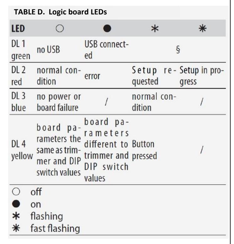
LOGIC BOARD LEDS
There are 4 LEDs on the Logic board:
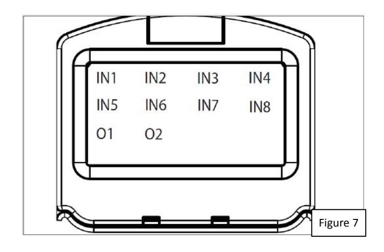
2.2 INPUTS AND OUTPUTS STATUS CHECK
The status of each input and output can be checked via the AUTO-PROG.
Go to menu 2.5.9. The display indicates the status of the logic as shown in Figure 7. Example:
IN1 = input active
IN1 = input not active
2.3 AUTOMATION STATUS CHECK
The current status of the door automation system can be checked via the AUTO-PROG.
Go to menu 2.5.10. The display shows information regarding the status of the door automation as shown below in Table E.
| TABLE E. Door Status |
|---|
2.4 WARNINGS
Warnings provide information regarding the status or current phase of the door operator and alerts that may prevent it from operating. It is possible to check any current warnings via the AUTO-PROG.
Go to menu 4 to view the list of current alerts. If there is at least one alert, a bell icon appears on the upper left corner of the home screen.
| TABLE F. Warnings |
|---|
| AUTO-PROG (battery req'd) |
| AUTO-PROG fault |
2.5 ERRORS
Errors are malfunctions that prevent the automation system from working. They are indicated by a steady red LED on the Logic board.
After every 5 minutes in which a fault condition persists and for a maximum of 20 consecutive times, the AutoEntryControl will perform a Reset to attempt to restore normal operation so as not to require any action if the condition that caused the error was temporary. If the fault persists, remove the cause in order to restore normal operation.
The type of error can be identified via the AUTO-PROG. The error code appears on the home page. Go to menu 5; the display provides information regarding the current error.
When an error occurs:
- 1. Check all the electrical connections
- 2. Carry out a reset.
- 3. If the problem persists, carry out the operations described in the Table G below, one at a time, until the problem is resolved.
| TABLE G. ERRORS | |
|---|---|
| Eprom failure | |
| 24 | Consecutive obstacles in closing |
|
|---|---|---|
| 26 | Lock failure |
|
| 27 | Motor rotation fault | - Check the polarity of the motor cable |
| 31 | Consecutive obstacles in opening |
|
| 39 | Setup data missing or corrupted |
- Perform Setup
- Replace the Logic board |
OTHER BOARD DATA
Go to menu 2.5.11 of the AUTO-PROG. The display provides information on the following parameters:
- V MAIN : input voltage to the Logic board (Volts)
- V ACC : output voltage for accessories (Volts)
- POS : position of the rotating shaft (degrees)
- I MOT : current drawn by motor (Amperes)
2.7 FIRMWARE VERSIONS
Go to menu 9 of the AUTO-PROG to view the firmware versions of the bootloader, the Logic board and the AUTO-PROG.
2.8 LOG DATA
The AutoEntryControl records the last 512 system events. A battery must be installed on the Logic board in order to save the list of events in memory even if the system is switched off.
3. NETWORKING MULTIPLE OPERATORS
■ DESCRIPTION
The AutoEntryControl is capable of communicating with other AutoEntryControl units via a serial data network connection.
This enables the following modes of operation to be used (AUTO-PROG menu 2.6.1):
- INTERMODE: a master door from which to set the operating mode for all the other doors that are connected to the network.
- INTERLOCK: two single doors, where the opening of one is subject to the closing of the other and vice versa.
- 2 LEAVES: access consisting of a pair of doors.
- 2 LEAVES + INTERLOCK: two interlocked accesses, each consisting of a pair of doors.

Every network connected AutoEntryControl should be programmed for the same network mode.
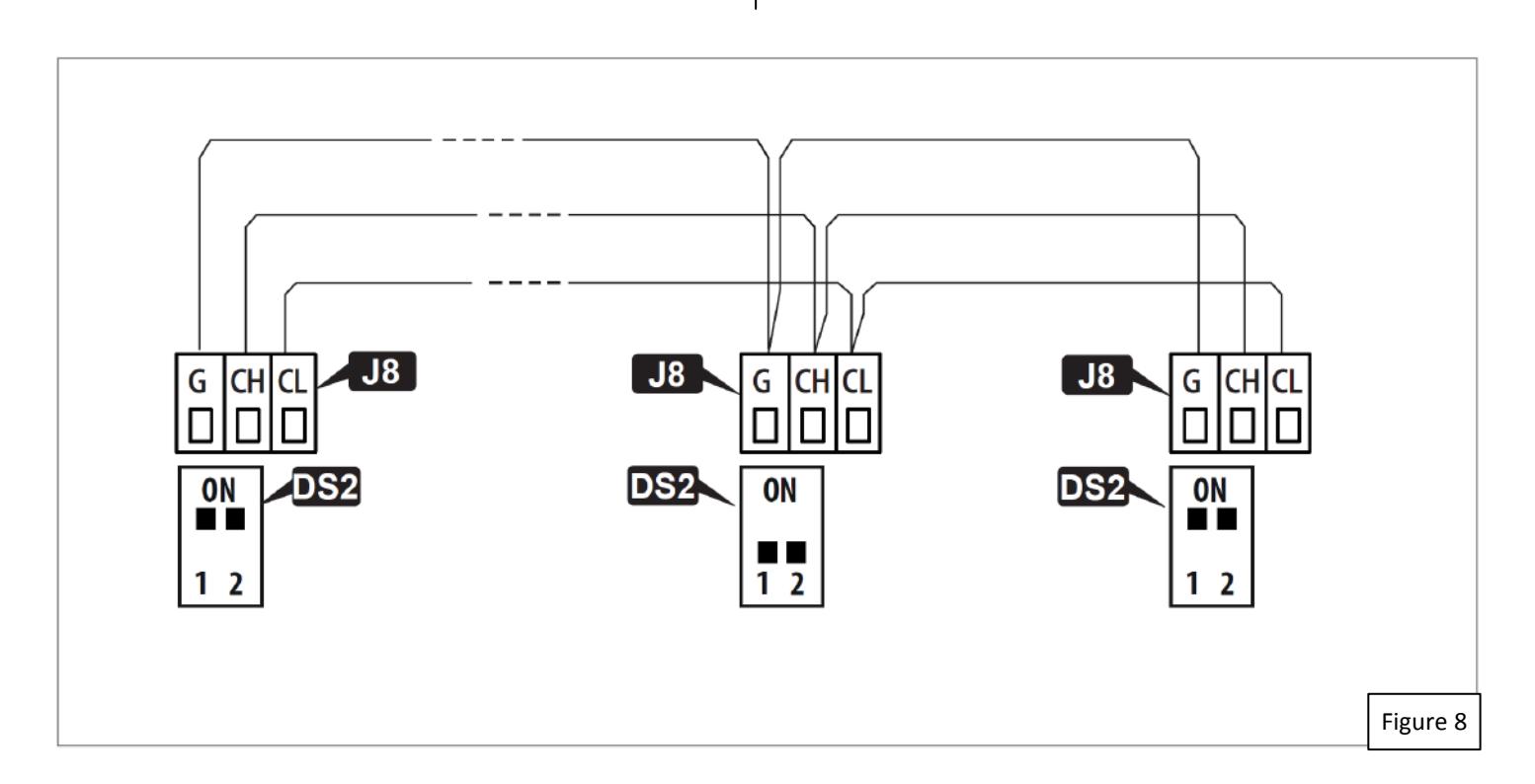
■ CONNECTION
The units in the network are connected via 3 daisy-chained connected wires between the grey J8 connectors of the I/O boards (Figure 8).
The sequence in which the units are wired is unimportant, but it is essential that a DAISY-CHAIN connection is used.
The 2 DIP switches on the I/O board must be set as follows:
- On the first and last units of the cascade connection: both ON.
- On intermediate units (if any): both OFF.
■ ADDRESSING
A unique ID (AUTO-PROG menu 2.6.2) must be assigned to each AutoEntryControl in the network as indicated below. Do not assign the same ID to more than one unit in the network.
■ REGISTRATION
After having wired up and assigned an address to each unit, registration (AUTO-PROG menu 2.6.3), must only be carried out on the AutoEntryControl that has been assigned ID1.
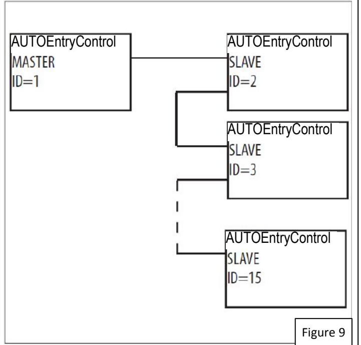
3.1 INTERMODE
Figure 9 shows the ID to assign to the AutoEntryControl units in the network.
The system consists of a Master unit and a maximum of 14 Slave units. The AutoEntryControl Master unit is the only one on which the operating mode should be set, which is then also applied immediately to all the Slave units.

With INTERMODE, it is not possible to change the operating mode of an individual unit.
The Master unit must be assigned ID1 and the Slave units with ID from 2 to 14.
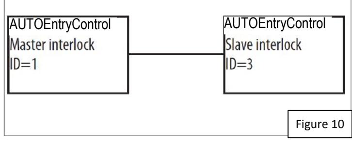
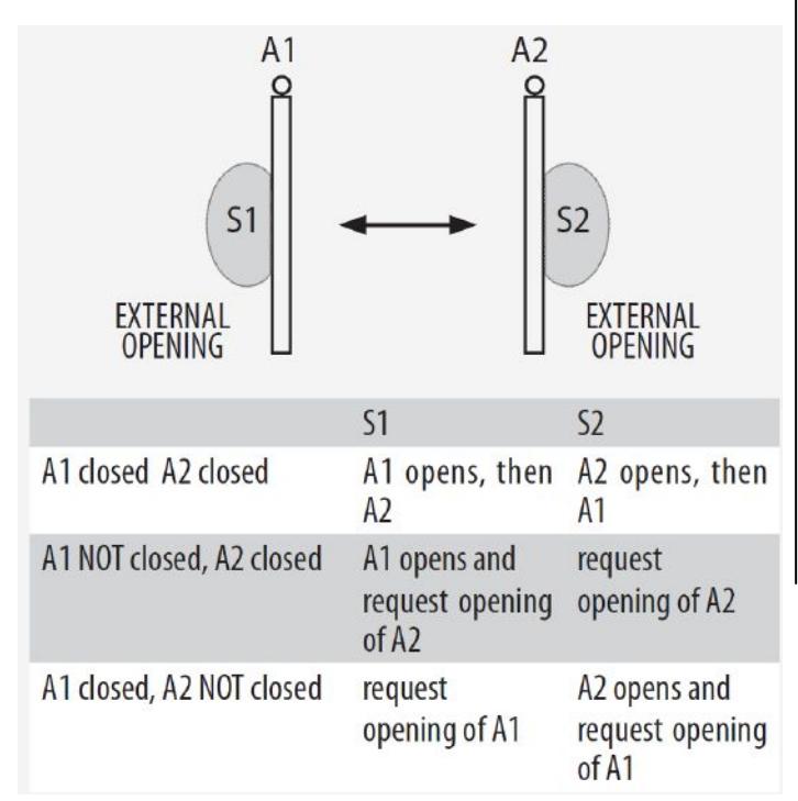
3.2 INTERLOCK
Figure 10 shows the ID to assign to the AutoEntryControl units in the network.
Either of the two units can be designated as the Master and the other as the Slave. In INTERLOCK mode, one door can open only if the other is closed. The available variations are shown below.
If the PARTIAL mode is associated with INTERLOCK, only the Master leaf opens.

Connect the devices and carry out the programming and Setup of the individual AutoEntryControl units before configuring the INTERLOCK using AUTO-PROG.

Select on the Master unit to activate the
INTERLOCK WITH NO MEMORY
With 4 sensors: the second opening is not automatic. In order to open the door, the internal/external sensor must be triggered when the other door is closed. If the sensor is activated while the door is not yet closed, it has no effect.
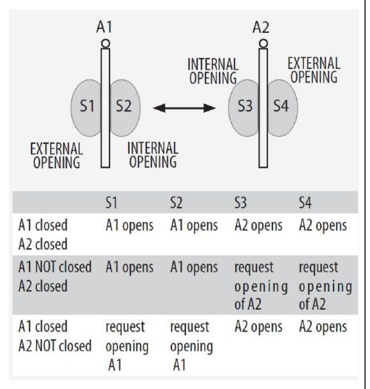
INTERLOCK WITH MEMORY
With 2 sensors or buttons: the second opening is automatic.
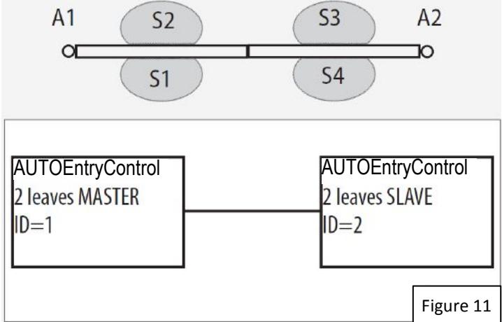
3.3 PAIR OF DOORS
Figure 11 shows the ID to assign to the AutoEntryControl units in the network.
If the two doors overlap, the one that opens first is designated as the Master. If there is no overlap, either of the two units can be designated as the Master and the other as the Slave.
The movement of the 2 leaves is synchronized.

The internal / external door sensors and safety devices must be connected to their own unit; all other devices are connected only to the Master. Connect the devices and carry out the programming and Setup of the individual AutoEntryControl units before activating the 2 LEAF function.
Only use the Master AutoEntryControl to change the operating mode.
The leaf opening / closing delay can be set in menu 2.5.6 of the AUTO-PROG.
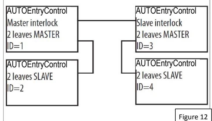
3.4 INTERLOCKED PAIRS OF DOORS
Figure 12 shows the ID to assign to the AutoEntryControl units in the network.
This configuration integrates the 2 LEAVES function (on two pairs of doors) with the interlock function.
Refer to the operating modes described above.
4. OPERATOR MAINTENANCE

Always shut off the power supply before performing any maintenance operations. If the disconnect switch is not in view, apply a warning sign stating "WARNING - Maintenance in Progress". Restore the power supply only after finishing any maintenance work and restoring the area to normal.

Maintenance must be performed by a qualified installer or maintenance technician.
Follow all safety recommendations and instructions given in this manual.
Mark off the work site and prohibit access/transit. Do not leave the work site unattended.
The work area must be kept tidy and cleared after maintenance has been completed.
Before starting work, wait for any hot components to cool down.
Do not make any modifications to the original components.
SDC shall bear no liability for damage or injury due to components that have been modified or otherwise tampered with.

The warranty shall be forfeited in the event of tampering with components. Only use SDC supplied spare parts.
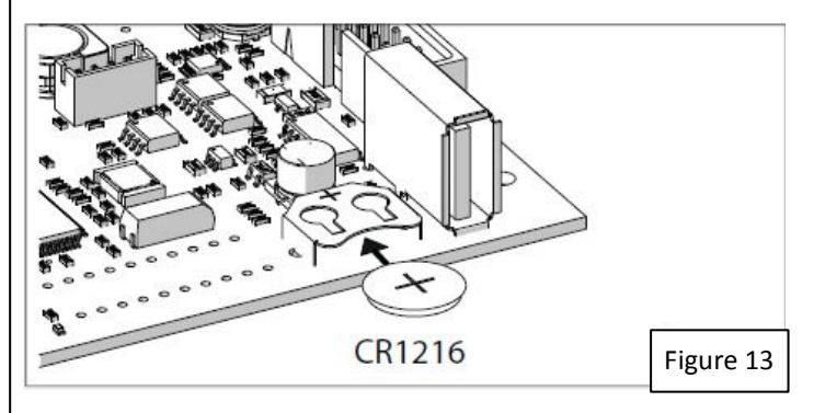
4.1 INSERTING / REPLACING THE BATTERY

CARRY OUT THE FOLLOWING OPERATIONS WITH THE ELECTRICITY SUPPLY DISCONNECTED
- 1. Remove the cover.
- 2. Install or replace the CR1216 battery on the Logic board, as shown in Figure 13 .
- 3. Reinstall the cover.
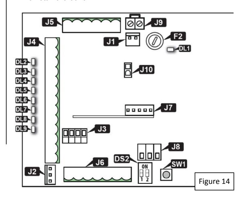
4.2 REPLACING THE FUSE

CARRY OUT THE FOLLOWING OPERATIONS WITH THE ELECTRICITY SUPPLY DISCONNECTED
There is a power supply protection fuse on the I/O board. To replace it:
- 1. Contact the factory to obtain a replacement fuse or use a suitable replacement (Littelfuse P/N 02183.15HXP or similar).
- 2. Remove the cover
- 3. See Figure 14 below to locate fuse F2. Carefully replace the fuse.
- 4. Reinstall the cover.
5.3 ROUTINE MAINTENANCE
Table H lists the suggested operations which must be performed on a regular basis in order to keep the automation working reliably and safely; these are given purely as a guideline and should not be considered exhaustive. The installer/maintenance technician is ultimately responsible for drawing up the maintenance plan for the automation, supplementing this list or modifying the maintenance plan on the basis of the operational characteristics.
TABLE H. Scheduled Maintenance
| Check the presence, integrity and legibility of the AUTOMATIC DOOR warning sign(s). |