Auditcon 2 Series – Round Housing Dead Bolt Installation Instructions
Open the original PDF document
View PDF

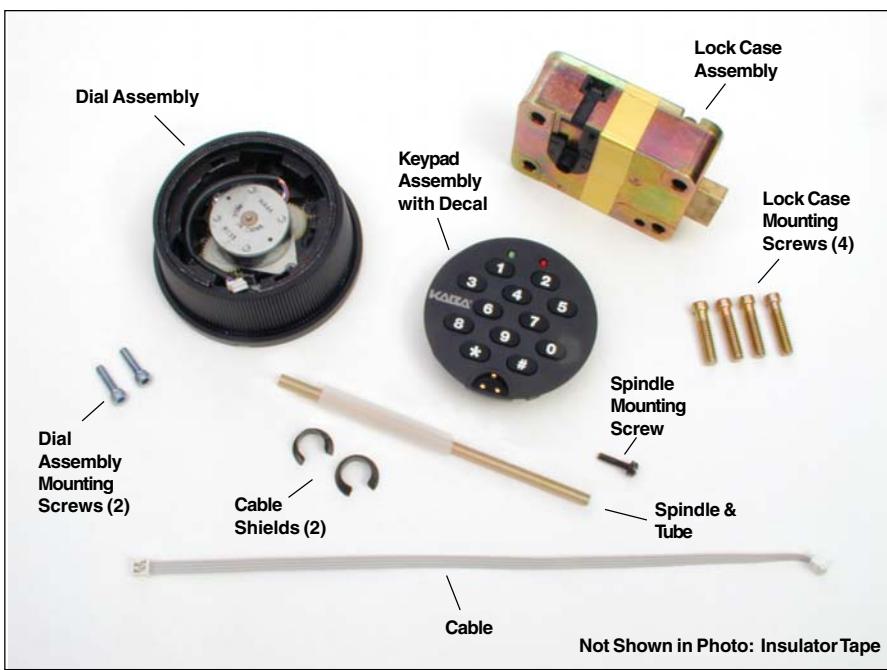
Figure 1 - Dead Bolt Lock Parts
The installation instructions are the basis for Security Agency Approvals. The lock installation must be done in accordance to these instructions in order to maintain the labeled approval level.
Design Parameters for Auditcon 2 Series Locks
- 1. Bolt dimensions (nominal): .312 inches x 1.000 inches/8 x 25.4mm
- 2. Bolt movement (nominal): .465 inches/11.8mm
- 3. Bolt extension: .465 inches/11.8 mm
- 4. Maximum load movable by the bolt: 5 lbs. (22N)
Note: Auditcon 2 dead bolt locks may not open if more than 5 lbs. (22N) of force is applied to the end or side of the bolt.
- 5. Maximum load against bolt when thrown (all directions): 224.8 lbs. (1kN)
- 6. The lock can be fitted to safes or vault doors of any material.
Note: As is the case with all mechanical and electronic locking devices, the container and boltworks must be designed to protect the lock.
Basic Tools and Materials Needed
- Medium Phillips head screwdriver (#2) (recommend magnetized tip)
- 9/64" Allen Wrench
- Fine pitch hacksaw (32 teeth/inch)
- Small flat file
- All-purpose scissors
- Tape measure or ruler
- ESD wrist band
Recommended, but not required:
- Torque screwdriver (30 inch-pounds/3.4 newton-meters capacity)
- Small vise grip
- Loctite<sub>®</sub> 262 (Red) for use on lock case mounting screws
WARNING: Kaba Mas locks are protected from 25,000 V Electrostatic Discharge (ESD) damage when correctly installed. Follow these precautions to avoid ESD damage when installing the lock:
- Handle the keypad assembly by the outer edge only.
- Use an ESD wrist band grounded to the lock or container during installation.
_____
Prepare for New Installation of the Lock (If Required)
- Use the template provided to establish the exact locations (relative to the spindle hole) of the mounting holes for the lock assembly.
- 2. The spindle hole diameter can be a minimum of .406" (10.3mm) to a maximum of .438" (11.1mm). The .406" (10.3mm) diameter is recommended. Spindle hole must be deburred.
- 3. The dial assembly mounting screws require drilled and tapped holes to 3/8" (9.5mm) depth if possible (minimum 1/4" or 6.4mm depth required.) Drill either the two horizontal mounting holes or the two vertical holes.
- 4. When mounting the lock unit (i.e., integrating it in a boltwork), make sure that the lock bolt has clearance to freely move to its end positions and that the shifting force works only in the axial direction (direction of movement). Lateral forces should not be exerted on the lock.
- 5. If other parts of the boltwork are to be connected to the lock unit (e.g., for activating a blocking device), corresponding adapters can be fixed with screws (#10-32 or M4) to the front of the lock bolt (tightening torque for 15mm screwing depth: 200Ncm maximum).
Part I: Install Lock Case Assembly
WARNING: <u>Do not take the lock case assembly apart.</u> There are no field servicable parts inside lock case.
- 1. Insert a cable shield into the deburred spindle hole from the back side of the container door.
- 2. Place the protective tube over the tube retainer on the lock case. (Figure 2)
- While holding the lock case assembly, guide the tube through the spindle hole and place the lock case flush against the inside of the container door.
- 4. Mark the tube flush to the outside of the container door (to within 1/16" or 1.6mm).
- 5. Remove lock case assembly from door and cut the tube just inside your mark.
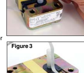
- 6. Plug one end of the ribbon cable into the connector on the bottom of the lock case. (Figure 3)
- 7. Lay the ribbon cable in the cable routing path on the lock case and tape the cable to the outside of the tube with the insulator tape provided. (Figure 3)
- 8. Hold the lock case assembly and carefully guide the loose end of the ribbon cable and the tube through the spindle hole so that they are accessible outside of the container door.
- 9. Mount the lock case assembly to the inside of the container door using the four 1/4-20 (or M6-1) lock case mounting screws. (Torque 25-30 lbs., 2.8-3.4 N-M)
Note: It is recommended that you use Loctite<sub>®</sub> 262 (Red) on the lock case mounting screws.
- 10. Insert the end of the spindle with the screw hole into the lock case assembly until the spindle is properly seated. The grooved side of the spindle should be oriented so that the grooves in the spindle align with the grooves in the drive cam. Turn the spindle to extend the bolt and ensure that the grooves are facing toward the bolt.
- 11. Mark the spindle shaft 3/8" (9.5mm) from the outside of the container door (plus or minus 1/16" or 1.6mm allowed). (Figure 4)
- Remove the spindle from the lock case to prevent damage to the cable while cutting.
- 13. Cut the spindle on the mark and deburr.
Figure 4
14. Re-insert the spindle. Refer to Step 10 for proper positioning.
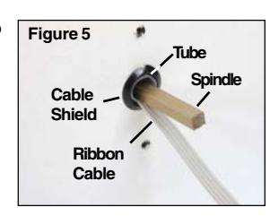
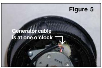
15. Insert the second cable shield into the spindle hole from the front of the container with the cable feeding through the center of it. (Figure 5)
Part II: Install Front Housing Assembly
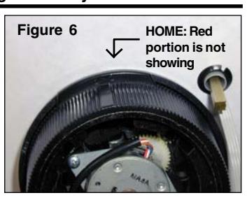
- 1. Hold the dial assembly in the upright position. (Red area on the dial assembly should be at top of dial). The lip on the dial should be positioned to cover the red area.This is referred to as the "HOME" position. (See correct dial position in Figure 6.)
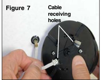
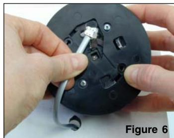
- 2. Guide the ribbon cable through the appropriate cable receiving hole, based on the orientation of the ribbon cable to the spindle. (Figure 7).
- 3. Align the dial assembly with the mounting holes and spindle, and position against the outside of the container door.
Caution: Do not turn the dial at this time as you could damage the cable.
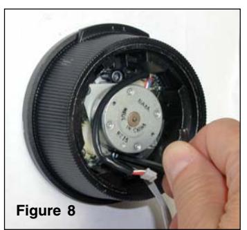
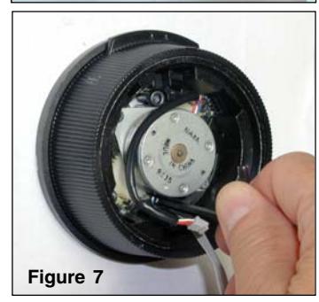
- 4. While holding the dial assembly in place, attach it to the container door using the two #8- 32 dial assembly mounting screws and the 9/64" Allen wrench. Tighten the screws (Torque 17-20 lbs., 1.9-2.25 N-M) and then ensure that the dial turns smoothly. (Figure 8)
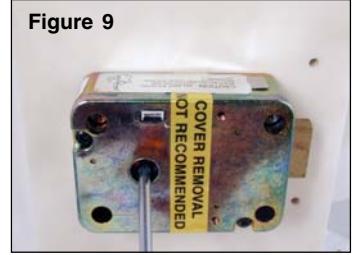
- 5. While holding the dial in place, insert the #6-32 spindle mounting screw through the back of the lock case and into the end of the spindle. (Figure 9) Turn the screw until it is securely attached to the spindle. (Torque 14-16 lbs., 1.6- 1.8 N-M)
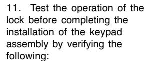
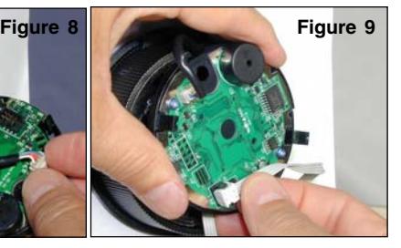
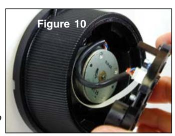
- 6. Insert the 4-pin generator cable on the dial assembly into the 4-pin connector on the back of the keypad assembly. The generator cable will only connect to the keypad assembly in one orientation. (Figure 10)
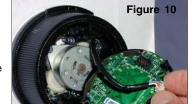
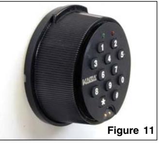
- 7. Insert the keyed Picoflex connector on the end of the ribbon cable into the connection header on the keypad. (Figure 11)
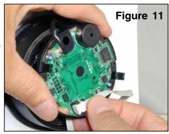
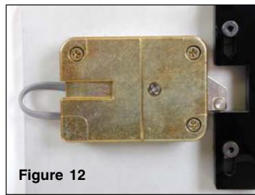
- 8. Position the generator cable and the ribbon cable around the generator in a counterclockwise direction to ensure that the cables will not be pinched when you attach the keypad assembly. (Figure 12).
- 9. Orient the lip of the dial to the HOME position.
Caution Next Step: Once the keypad assembly is snapped into place, it cannot be easily removed without performing an "uninstall" procedure. Do not snap the keypad assembly into place when performing the next step.
Note: If the keypad is not oriented correctly, you can remove the keypad and adjust the orientation of the dial assembly.
• Power the lock by turning the dial back and forth until simultaneous green and red
flashes display and two beeps sound to indicate that the lock is powered. Position the lock dial to the HOME position and key in the Factory Combination. (For a Model 52 or T52, enter "502550". For a Model 252 or 552, enter a two-digit number in the range from 01-20, followed by "502550".) If the combination is entered successfully, one green flash displays to indicate the lock is ready to open. To open, turn the dial right (clockwise) until the lock bolt is retracted. Then turn the dial back to the left to return the bolt to the extended position.
Note: After correctly entering a valid combination, you must retract the bolt within 4-6 seconds.
-
Figure 10
12. After successfully testing lock operation and verifying that none of the cables will be pinched, snap the keypad assembly into place.
- 13. Test the operation of the lock again. If the lock does not operate properly, refer to the following instructions to "Uninstall Keypad Assembly".
Uninstall Keypad Assembly
- 1. Remove the decal from the keypad assembly.
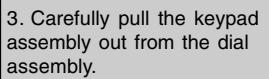
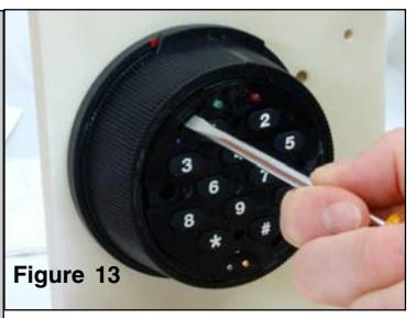
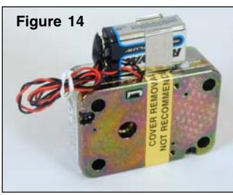
- 2. Insert a flat head screwdriver into the slot in the upper left hand corner of the keypad to release one of the two keypad catches. (Figure 14)

14. If your lock includes the Battery Assist option, you should now mount the battery clip inside the door near the lock and install a fresh 9 Volt Alkaline battery.
Note: To remove any excess cable or if you choose not to use the Battery Assist option, wrap and tie the battery assist cable. (Figure 14) If you do not ever plan on using the Battery Assist option, you can cut the cable next to the lock case to remove it.
© 2005-2006 Kaba Mas Corporation. All rights reserved. Product warranty information can be found at: www.kaba-mas.com
Kaba Mas Corporation 749 W. Short Street, Lexington, KY 40508 USA Phone: (859) 253-4744 FAX: (859) 255-2655 Customer Service: (800) 950-4744

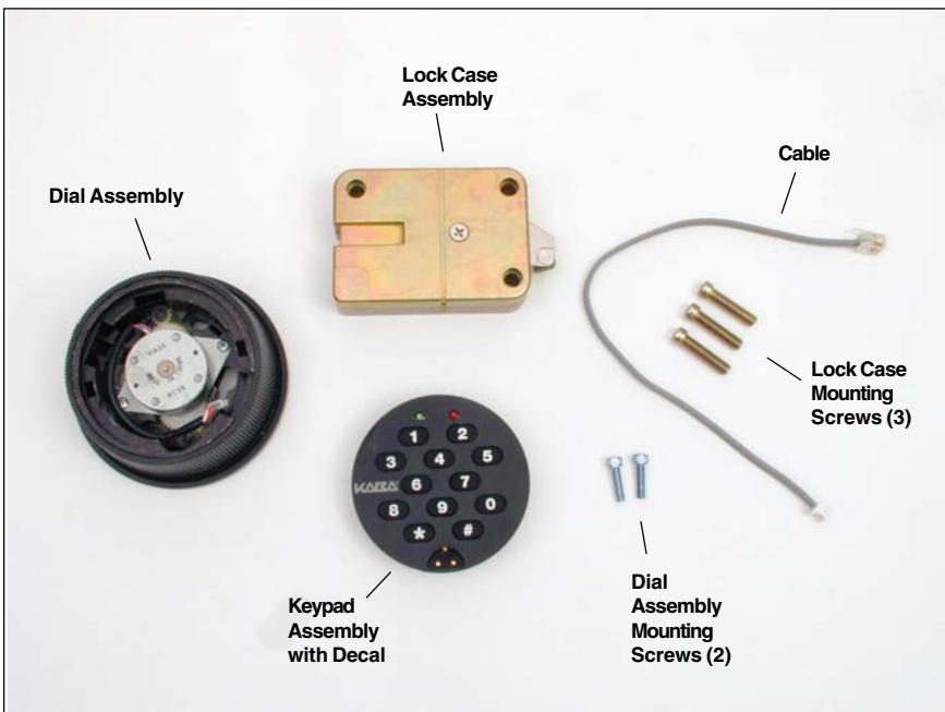
Figure 1 - Slide Bolt Lock Parts
The installation instructions are the basis for Security Agency Approvals. The lock installation must be done in accordance to these instructions in order to maintain the labeled approval level.
In order to maintain VdS Class 2/EN 1300 Class B lock approval levels in a container where multiple locks are required, special considerations must be observed. The Auditcon 2 Series lock must be the first one secured by the boltworks. Check the locked status of the container with the handle of the boltworks.
Design Parameters for Auditcon 2 Series Locks
- 1. Bolt dimensions (nominal): .312 inches x 1.000 inches/8 x 25.4mm
- 2. Bolt movement (nominal) : .465 inches/11.8mm
-
3. Bolt extension:
Square Nose Slide Bolt is .465 inches/11.8mm
- Roller Slide Bolt is .495 inches/12.6mm
- 4. Maximum load movable by the bolt: None
Note: Auditcon 2 slide bolt locks will not open if force is applied to the end or side of the bolt.
- 5. Maximum load against bolt when thrown (all directions): 224.8 lbs.(1kN)
- 6. The lock can be fitted to safes or vault doors of any material.
Note: As is the case with all mechanical and electronic locking devices, the container and boltworks must be designed to protect the lock.
Basic Tools and Materials Needed
- Medium Phillips head screwdriver (#2) (recommend magnetized tip)
- 9/64" Allen Wrench
- ESD wrist band
Recommended, but not required:
- Torque screwdriver (30 inchpounds/3.4 newton-meters capacity)
- Loctite® 262 (Red) for use on lock case mounting screws
WARNING:Kaba Mas locks are protected from 25,000 V Electrostatic Discharge (ESD) damage when correctly installed. Follow these precautions to avoid ESD damage when installing the lock:
- Handle the keypad assembly by the outer edge only.
- Use an ESD wrist band grounded to the lock or container during installation.
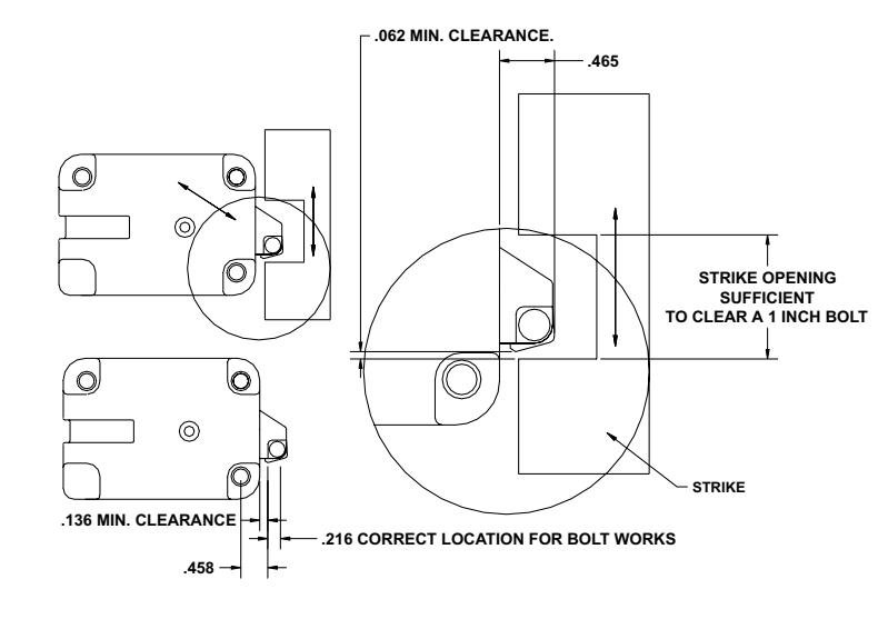
Figure 2 - Square Nose Slide Bolt Clearances and Positioning
Prepare for New Installation of the Lock
(If Required)
1. Using the lock parts along with the template provided, establish the exact location for the drilled and tapped holes.
Caution: The lock case must be mounted exactly according to the template if mounted over the cable routing hole. Otherwise, the lock case must be mounted so that no part of the case covers the cable routing hole.
- 2. The spindle hole diameter can be a minimum of .406" (10.3mm) to a maximum of .438" (11.1mm). The .406" (10.3mm) diameter is recommended. Spindle hole must be deburred.
- 3. The dial assembly mounting screws require drilled and tapped holes to 3/8" (9.5mm) depth if possible (minimum 1/4" or 6.4mm depth required.) Drill either the two horizontal mounting holes or the two vertical holes.
- 4. When mounting the lock unit (i.e., integrating it in a boltwork), make sure that the lock bolt has clearance to freely move to its end positions and that the shifting force works only in the axial direction (direction of movement). Lateral forces should not be exerted on the lock. A minimum clearance of 1/16" (1.6mm) is required between the bolt roller/nose and the inside edge of the strike. Refer to Figures 2 and 3.
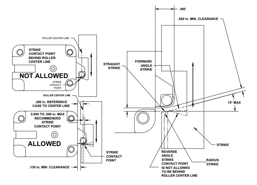
Figure 3 - Roller Slide Bolt Clearances, Strike Types & Contact Points
Part I: Install Front Housing Assembly
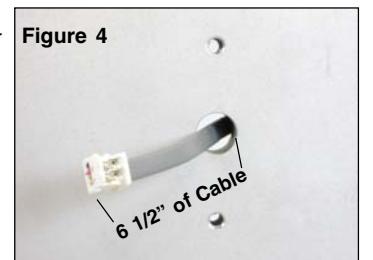
- 1. Route the end of the lock cable with the Picoflex connector from the back of the container door through the cable routing hole so that approx. 6 1/2" (165.1mm) of the cable is available from the front. (Figure 4)
- 2. Hold the dial assembly in the upright position. (The generator cable should be positioned at approximately one o'clock.) (Figure 5)
- 3. Guide the ribbon cable through the cable receiving hole. (Figure 6).
- 4. Align the dial assembly with the mounting holes, and position against the outside of the container door, ensuring that 6 1/2" (165.1mm) of cable is still available from the front.
- 5. While holding the dial assembly in place, attach it to the container door using the two #8-32 dial assembly mounting screws and the 9/64" Allen wrench. Tighten the screws (Torque 17-20 lbs., 1.9-2.25 N-M) and then ensure that the dial turns smoothly. (Figure 7)
- 6. Insert the 4-pin generator cable on the dial assembly into the 4-pin connector on the back of the keypad assembly. The generator cable will only connect to the keypad assembly in one orientation. (Figure 8)
- 7. Insert the keyed Picoflex connector on the end of the ribbon cable into the connection header on the keypad. (Figure 9)
8. Position the generator cable and the ribbon cable around the generator in a counter-clockwise direction to ensure that the cables will not be pinched when you attach the keypad assembly. (Figure 10)
Caution Next Step: Once the keypad assembly is snapped into place, it cannot be easily removed without performing an "uninstall" procedure. Do not snap the keypad assembly into place when performing the next step.
- 9. Align the keypad assembly in the upright position and carefully insert the two catches on the keypad assembly into the notches on the dial assembly, but do not snap the keypad assembly into place . (Figure 11)
- 10. Plug the RJ11 end of the cable into the lock case in order to test the lock.
- 11. Test the operation of the lock before completing the installation of the keypad assembly by verifying the following:
Note: If the keypad is not oriented correctly, you can remove the keypad and adjust the orientation of the dial assembly.
• Power the lock by turning the dial back and forth until simultaneous green and red flashes display and two beeps sound to indicate that the lock is powered. Key in the Factory Combination. (For a Model 52 or T52, enter "502550". For a Model 252 or 552, enter a two-digit number in the range from 01-20, followed by "502550".) If the combination is entered successfully, continuous green flashes display to indicate that the lock is ready to open. Rotate the container handle to unlock. Then rotate the handle back to the locked position.
Note: After correctly entering a valid combination, you must retract the bolt within 4-6 seconds.
- 12. Unplug the RJ11 end of the cable from the lock case and lay the case aside.
- 13. After successfully testing lock operation and verifying that none of the cables will be pinched, snap the keypad assembly into place.
Part II: Install Lock Case Assembly
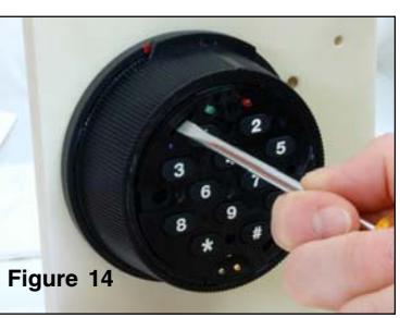
WARNING: Do not take the lock case assembly apart. The lock will not operate if the back cover has been removed.
1. Ensure that the cable lays in the cable channel as you mount the lock case assembly to the inside of the container door using the three 1/4-20 (or M6-1) screws (Torque 25-30 lbs., 2.8-3.4 N-M), allowing 1/16" (1.6mm) clearance between the lock bolt and the container locking bar. (See Figure 2 for proper clearances and positioning when installing a square nose slide bolt. See Figure 3 for proper clearances, strike types and contact points when installing a roller slide bolt.)
Note: The lock case assembly can be mounted in bolt roller up position or bolt roller down position (Figure 12) for all mounting locations. It is recommended that you use Loctite® 262 (Red) on the lock case mounting screws.
lock again. If the lock does not operate properly, refer to the following instructions to "Uninstall Keypad Assembly".
Uninstall Keypad Assembly
1. Remove the decal from the keypad assembly.
2. Test the operation of the
- 2. Insert a flat head screwdriver into the slot in the upper left hand corner of the keypad to release one of the two keypad catches. (Figure 13)
- 3. Carefully pull the keypad assembly out from the dial assembly.
- 4. Check for pinched or detached cables.
3. If your lock includes the Battery Assist option, you should now mount the battery clip inside the door near the lock and install a fresh 9 Volt Alkaline battery.
Note: To remove any excess cable or if you choose not to use the Battery Assist option, wrap and tie the battery assist cable. (Figure 14) If you do not ever plan on using the Battery Assist option, you can cut the cable next to the lock case to remove it.
© 2005-2006 Kaba Mas Corporation. All rights reserved. Product warranty information can be found at: www.kaba-mas.com
Kaba Mas Corporation 749 W. Short Street, Lexington, KY 40508 USA Phone: (859) 253-4744 FAX: (859) 255-2655 Customer Service: (800) 950-4744