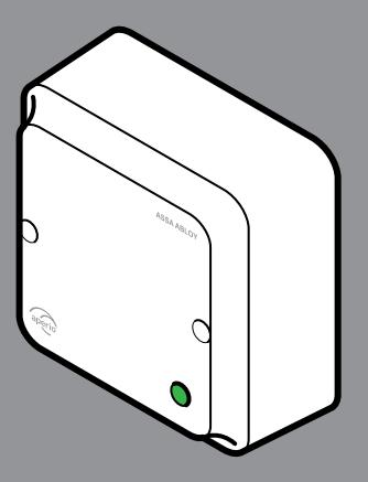
Aperio AH40 (GEN5) Hub Installation Guide
Open the original PDF document
View PDF

Aperio® AH40 (GEN5) Hub Installation Guide Experience a safer
and more open world
1
AH40 - Table of Contents
| AH40 - FCC and ISED Canada Statements | : |
|---|---|
| AH40 - Placement of Communication Hub | |
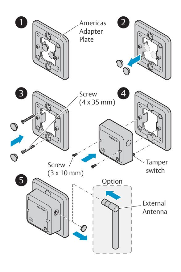
| AH40 - Mounting, Americas Adapter Plate | 6 |
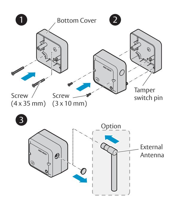
| AH40 - Mounting, Bottom Cover | 7 |
| AH40 - Connectors | |
| AH40 - Jumpers | . 9 |
| AH40 - Communication Hub LED Indications | 1( |
| AH40 - Technical Data | 11 |

Conforms to EN 62368-1 and UL/CSA 62368-1
AH40 - FCC and ISED Canada Statements
FCC Statements
Changes or modifications to the equipment not expressly approved by the party responsible for compliance could void the users authority to operate the equipment.
This device complies with Part 15 of the FCC Rules. Operation is subject to the following two conditions: (1) This device may not cause harmful interference, and (2) This device must accept any interference received, including interference that may cause undesired operation.
Note: This equipment has been tested and found to comply with the limits for a Class B digital device, pursuant to Part 15 of the FCC Rules. These limits are designed to provide reasonable protection against harmful interference in a residential installation. This equipment generates, uses and can radiate radio frequency energy and, if not installed and used in accordance with the instructions, may cause harmful interference to radio communications. However, there is no guarantee that interference will not occur in a particular installation.
If this equipment does cause harmful interference to radio or television reception, which can be determined by turning the equipment off and on, the user is encouraged to try to correct the interference by one of the following measures:
- - Reorient or relocate the receiving antenna.
- - Increase the separation between the equipment and receiver.
- - Connect the equipment into an outlet on a circuit different from that to which the receiver is connected.
- - Consult the dealer or an experienced radio/TV technician for help.
FCC RF Radiation Exposure Statement
This equipment complies with FCC RF radiation exposure limits set forth for an uncontrolled environment. The device and its antenna must not be co-located or operating in conjunction with any other antenna or transmitter.
ISED Canada Statements
This radio transmitter [IC:9504A-AH40R03] has been approved by Innovation, Science and Economic Development Canada to operate with the antenna types listed below, with the maximum permissible gain indicated. Antenna types not included in this list that have a gain greater than the maximum gain indicated for any type listed are strictly prohibited for use with this device.
| Antenna type | Maximum antenna gain (dBi) | Impedance (ohm) |
|---|---|---|
| Internal antenna | 3.6 | 50 |
| AH-ANTENNA-1 | 2.15 | 50 |
This device contains licence-exempt transmitter(s)/receiver(s) that comply with Innovation, Science and Economic Development Canada's licence-exempt RSS(s). Operation is subject to the following two conditions:
- (1) This device may not cause interference.
- (2) This device must accept any interference, including interference that may cause undesired operation of the device.
Le present émetteur radio [IC:9504A-AH40R03] a été approuvé par Innovation, Sciences et Développement économique Canada pour fonctionner avec les types d'antenne énumérés ci dessous et ayant un gain admissible maximal. Les types d'antenne non inclus dans cette liste, et dont le gain est supérieur au gain maximal indiqué pour tout type figurant sur la liste, sont strictement interdits pour l'exploitation de l'émetteur.
| Type d'antenne | Gain d'antenne maxima (dBi) | Impédance (ohm) |
|---|---|---|
| Antenne interne | 3.6 | 50 |
| AH-ANTENNA-1 | 2.15 | 50 |
L'émetteur/récepteur exempt de licence contenu dans le présent appareil est conforme aux CNR d'Innovation, Sciences et Développement économique Canada applicables aux appareils radio exempts de licence. L'exploitation est autorisée aux deux conditions suivantes :
- 1) L'appareil ne doit pas produire de brouillage;
- 2) L'appareil doit accepter tout brouillage radioélectrique subi, même si le brouillage est susceptible d'en compromettre le fonctionnement.
AH40 - Placement of Communication Hub
For hubs using the internal antenna , it is recommended that the device to hub distance be limited to 25 m (80 ft) . The internal antenna has an oblong coverage area and is most appropriate for applications where the hub is directly facing the device(s), e.g. mounting on the wall at the end of a hallway of doors.
For hubs using the e xternal antenna , it is recommended that the device to hub distance be limited to 12.5 m (40 ft) . The external antenna has a torus shaped coverage area and is most appropriate for applications where the devices are surrounding the hub, e.g. mounting on the ceiling less than 5m/16ft high in a room or hallway.
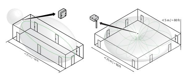
Examples of placement of the Hub with internal and external antenna. AH40 can manage up to 64 locks.
Note: AH40 must be installed into a junction box ex European 2-Gang, using Aperio bottom cover or Americas adapter plate connected to junction box. AH40 must be installed by qualified and trained personal. Indoor installation only!
AH40 - Mounting, Bottom Cover (EU version)
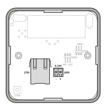
| Connectors | Description |
|---|---|
| J700 |
Ethernet connector. Connection to the Electronic
Access Control system through a 10BASE-T / 100BASE TX Local Area Network. Can also be used for power supply if connected to a IEEE 802.3.af compliant Power Sourcing Device (PSE). Wire requirements CAT5 or higher. |
| J800 |
Power supply input, 8-24 VDC, 1.2 W. The power supply
shall be 3 A over current protected. Wire requirements 16-22 AWG. |
Note: When PoE (Power over Ethernet) is used, no power supply should be connected to J800. The installation must comply with national wiring regulations.
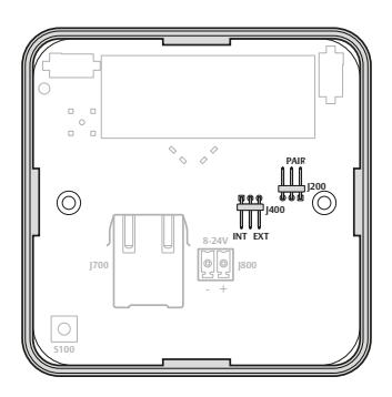
| Jumpers | Description |
|---|---|
|
J400
ANTENNA |
Select external antenna by connecting the two right
pins.Select internal antenna by connecting the two left pins. |
|
J200
PAIR |
Select pairing mode by connecting the two right pins.
Note: If the pairing jumper if removed within 10 seconds from from boot up and the Hub LED is lit, all paired devices will be unpaired. |
Note: To install an external antenna use a thin screwdriver and gently bend the antenna cap loose. Be careful, there are sensitive components behind the cap!
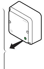
AH40 - Communication Hub LED Indications
The Communication Hub has a status LED visible through the front cover. It supports optical schemes with red, green and yellow. The indication schemes are described by the figure below:
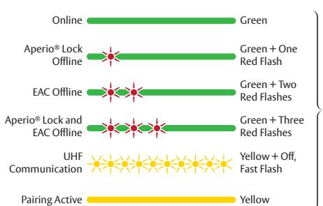
Note: With the software tool Aperio ® Programming Application and an USB radio dongle, further system installation parameters can be set.
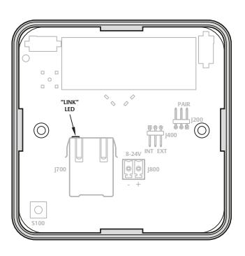
The "LINK" LED on the Ethernet connector indicates both status of the Ethernet Link level and if communication is ongoing.
AH40 - Technical Data
| Physical Dimensions | 82 mm x 82 mm x 37 mm (H x W x T) |
|---|---|
| Power Supply | 8-24 VDC or Power over Ethernet (PoE) |
| Power Rating |
The power supply shall be able to deliver minimum
1.2 W and be 3 A over current protected. Wire requirements 16-22 AWG. PoE IEEE 802.3.af compliant class 1 Powered device (PD) |
| Ethernet | 10BASE-T / 100BASE-TX Local Area Network |
| Radio Standard |
IEEE 802.15.4 (2400 – 2483,5 MHz)
16 channels (11-26) AES 128 bit encryption |
| Receiver Sensitivity | -100 dBm |
|
Wireless Transmit
Power |
10 dBm/MHz. Peak value from average detector
according to EN ETSI 300 328 Maximum spectral density. |
|
Wireless Operating
Range |
Indoors up to 25 m depending upon installed
environment. |
| Internal Antenna | Two port cross polarized patch antenna. |
| External Antenna |
One reverse polarity SMA external antenna
connector. AH40 is certified to be used with ASSA ABLOY external antenna AH ANTENNA 1. If other external antenna is used it must be of same type (dipole) and not have larger antenna gain than 3.6 dBi. |
|
Operating
Temperature |
5 °C to 35 °C |
| Humidity | < 95 % non-condensing |
| IP Classification | IP20 |
| Safety, Radio and EMC |
IEC 62368-1:2014
EN 62368-1:2014 + A11:2017 UL/CSA 62368-1:2014 EN 301 489-1 V2.1.1 EN 301 489-17 V3.2.0 EN 300 328 V2.2.2 EN 50130-4:2011 + A1:2014 EN 62311 FCC 47CFR Part 15 subpart B and subpart C ISED RSS-247 and ICES-003 AS/NZS 4268 |
|
Number of supported
locks/sensors |
64 |
The ASSA ABLOY Group is the global leader in access solutions. Every day we help people feel safe, secure and experience a more open world.

12
www.assaabloy.com/aperio