Aperio AH20, AH30 (GEN5) Hub Installation Guide
Open the original PDF document
View PDF

Aperio® AH20/AH30 (GEN5) Hub Installation Guide
Experience a safer and more open world
1
AH20/AH30 - Table of Contents
|
AH20/AH30 - FCC and ISED Canada Statements
|
3 |
|---|---|
| AH20/AH30 - Placement of Communication Hub | 5 |
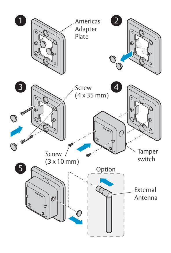
| AH20/30 - Mounting, Americas Adapter Plate (US version) | 6 |
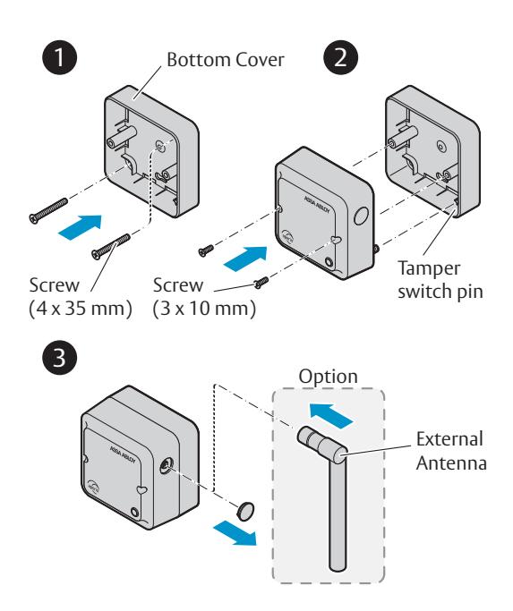
| AH20/30 - Mounting, Bottom Cover (EU version) | 7 |
|
AH20 (J101) - Connections
|
8 |
|
AH20 Advanced Wiegand (J100) - Connections
10 |
|
| AH20 - DIP Switch Configuration Table (S700)11 | |
| AH30 (J101) - Connections12 | |
| AH30 - DIP Switch Configuration Table (S700)13 | |
| AH30 - RS485 Bus Connection14 | |
|
AH30 - RS485 Addressing
15 |
|
| AH20/AH30 - Communication Hub LED Indication17 | |
| AH20/AH30 - Technical Data18 |

AH20/AH30 - FCC and ISED Canada Statements
FCC Statements
Changes or modifications to the equipment not expressly approved by the party responsible for compliance could void the users authority to operate the equipment.
This device complies with Part 15 of the FCC Rules. Operation is subject to the following two conditions: (1) This device may not cause harmful interference, and (2) This device must accept any interference received, including interference that may cause undesired operation.
Note: This equipment has been tested and found to comply with the limits for a Class B digital device, pursuant to Part 15 of the FCC Rules. These limits are designed to provide reasonable protection against harmful interference in a residential installation. This equipment generates, uses and can radiate radio frequency energy and, if not installed and used in accordance with the instructions, may cause harmful interference to radio communications. However, there is no guarantee that interference will not occur in a particular installation.
If this equipment does cause harmful interference to radio or television reception, which can be determined by turning the equipment off and on, the user is encouraged to try to correct the interference by one of the following measures:
- - Reorient or relocate the receiving antenna.
- - Increase the separation between the equipment and receiver.
- - Connect the equipment into an outlet on a circuit different from that to which the receiver is connected.
- - Consult the dealer or an experienced radio/TV technician for help.
FCC RF Radiation Exposure Statement
This equipment complies with FCC RF radiation exposure limits set forth for an uncontrolled environment. The device and its antenna must not be co-located or operating in conjunction with any other antenna or transmitter.
ISED Canada Statements
This radio transmitter [IC:9504A-AH20R03] has been approved by Innovation, Science and Economic Development Canada to operate with the antenna types listed below, with the maximum permissible gain indicated. Antenna types not included in this list that have a gain greater than the maximum gain indicated for any type listed are strictly prohibited for use with this device.
| Antenna type | Maximum antenna gain (dBi) | Impedance (ohm) |
|---|---|---|
| Internal antenna | 3.6 | 50 |
| AH-ANTENNA-1 | 2.15 | 50 |
This device contains licence-exempt transmitter(s)/receiver(s) that comply with Innovation, Science and Economic Development Canada's licenceexempt RSS(s). Operation is subject to the following two conditions:
- (1) This device may not cause interference. (2) This device must accept any interference, including interference that may cause undesired operation of the device.
- Le present émetteur radio [IC:9504A-AH20R03] a été approuvé par Innovation, Sciences et Développement économique Canada pour fonctionner avec les types d'antenne énumérés ci dessous et ayant un gain admissible maximal. Les types d'antenne non inclus dans cette liste, et dont le gain est supérieur au gain maximal indiqué pour tout type figurant sur la liste, sont
| Type d'antenne | Gain d'antenne maxima (dBi) | Impédance (ohm) |
|---|---|---|
| Antenne interne | 3.6 | 50 |
| AH-ANTENNA-1 | 2.15 | 50 |
strictement interdits pour l'exploitation de l'émetteur.
L'émetteur/récepteur exempt de licence contenu dans le présent appareil est conforme aux CNR d'Innovation, Sciences et Développement économique Canada applicables aux appareils radio exempts de licence. L'exploitation est autorisée aux deux conditions suivantes :
AH20/AH30 - Placement of Communication Hub
For hubs using the internal antenna , it is recommended that the device to hub distance be limited to 25 m (80 ft) . The internal antenna has an oblong coverage area and is most appropriate for applications where the hub is directly facing the device(s), e.g. mounting on the wall at the end of a hallway of doors.
For hubs using the e xternal antenna , it is recommended that the device to hub distance be limited to 12.5 m (40 ft) . The external antenna has a torus shaped coverage area and is most appropriate for applications where the devices are surrounding the hub, e.g. mounting on the ceiling less than 5m/16ft high in a room or hallway.
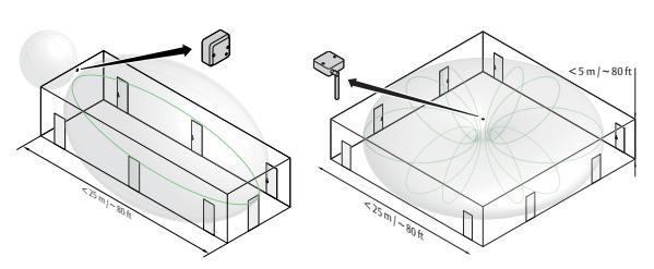
Examples of placement of the Hub with internal and external antenna.
AH30 (RS485 Hub) can manage up to 16 locks, AH20 and AH30 (1 - 1 mode) can manage 1 lock.
Note: AH20/AH30 must be installed into a junction box ex European 2-Gang, using Aperio bottom cover or Americas adapter plate connected to junction box. AH20/AH30 must be installed by qualified and trained personal. Indoor installation only!
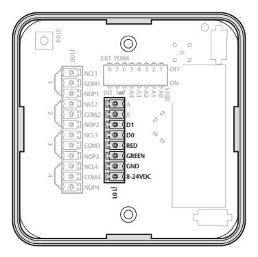
AH20 Advanced Wiegand Connectors (J101)
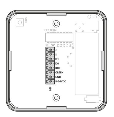
AH20 Standard Wiegand Connectors (J101)
Note: The installation must comply with national wiring regulations.
Communication Hub hardware version AH20 has four Wiegand signals plus power supply. The purpose and connection of these signals are described in the table below.
|
Hub
Connector |
Description |
|---|---|
| D1 |
Wiegand Data 1 signal. Output from Communication Hub.
Used to transmit credentials. |
| D0 |
Wiegand Data 0 signal. Output from Communication Hub.
Used to transmit credentials. |
| RED |
Wiegand Red LED signal. Input to Communication Hub. Used
for access decision. Leave unconnected if DIP switch 1 is selected "OFF". Signal is active low. |
| GREEN |
Wiegand Green LED signal. Input to Communication Hub.
Used for access decision. Signal is active low. See DIP 1 for alternate instructions. |
| GND |
GND = Signal ground. Should be connected to EAC system
GND and power supply GND. |
| 8-24 VDC |
Power supply input, 8-24 VDC, 2 W (AH20 Advanced)
alternatively 0.8 W (AH20 Standard and AH30). The power supply shall be 3 A over current protected. Wire requirements 16-22 AWG. |
AH20 Advanced Wiegand Connectors (J100)
| Relays | Description |
|---|---|
| Relay 1 | DPS (Door Position) |
| Relay 2 | RX (Request to exit) |
| Relay 3 | Battery Alarm Output |
| Relay 4 |
Tamper Alarm Output/
Lock Jammed |
| Relay Contacts | Description |
|---|---|
| NCL | Normally Closed |
| COM | Common |
| NOP | Normally Open |
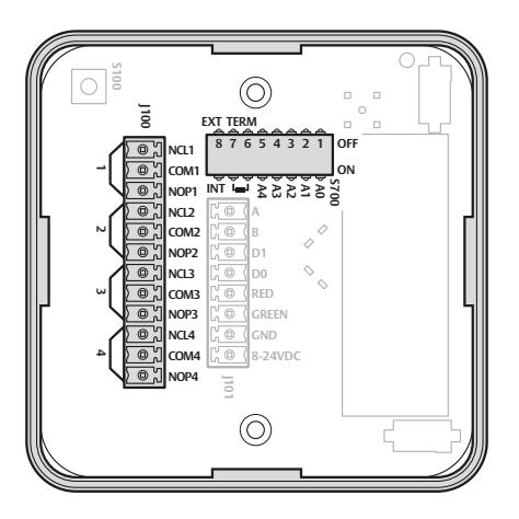
On the AH20 advanced Wiegand communication hub, four form C relays are available. The purpose of the four relays is to provide door status information to the EAC system.
The relays are connected to inputs on the EAC controller/ panel.
Relay max voltage: 30 VDC Relay max power: 15W
resistive load
|
DIP
Switch Number |
Label | Description |
|---|---|---|
| Controls use of Red LED signal for access decision. | ||
| 1 | A0 | ON => Red LED is used. |
| OFF => Red LED is ignored. | ||
| 2 | A1 | Set to OFF by default. Reserved for future use. |
| Controls addition of parity bits if required. | ||
| 3 | A2 | ON => Addition of parity bits is enabled. |
|
OFF => Addition of parity bits is disabled.
Credentials are transmitted as received. |
||
| Controls byte order of transmitted credentials. | ||
| 4 | A3 |
ON => The byte order is reversed on the Wiegand
interface compared to what is received from the Aperio® lock. |
| OFF => The byte order is left as is. | ||
| Used in "Pairing Mode". | ||
| A4 | ON => Starts in pairing mode. | |
| 5 | OFF => Normal use. | |
|
Note: If the DIP switch is moved from ON to OFF within
10 seconds from boot up and the Hub LED is lit, all paired devices will be unpaired. |
||
| 6-7 | Not applicable (only used for AH30). | |
| 8 |
INT/
EXT |
Internal/External Antenna Use, ON = Internal |
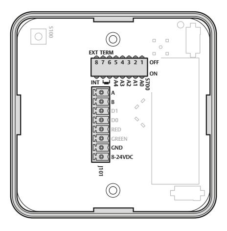
AH30 (J101) Connectors
|
Hub
Connector |
DESCRIPTION |
|---|---|
| A | RS485 Data A. |
| В | RS485 Data B. |
| GND | GND = Signal ground. Should be connected to EAC system GND and power supply GND. |
| 8-24 VDC | Power supply input, 8-24 VDC, 2 W (AH20 Advanced) alternatively 0.8 W (AH20 Standard and AH30). |
Note: The installation must comply with national wiring regulations.
AH30 - DIP Switch Configuration Table (S700)
|
DIP
Switch Number |
Label | Description |
|---|---|---|
| Controls RS485 addressing BIT 0-BIT 4. | ||
| ON => Address bit set. | ||
| 1-5 | A0-A4 | OFF => Address bit NOT set. |
|
See AH30 - RS485 Addressing Reference on page
15. |
||
| 6-7 | TERM |
Control use of termination resistor between RS485 A
and RS485 B. |
|
For termination to be enabled, both switches must
be set to ON. |
||
|
ON =>120 Ohm termination resistor connected/
enabled. |
||
|
OFF => 120 Ohm termination resistor disconnected/
disabled. |
||
| 8 | INT/EXT | Controls use of external antenna if required. |
| ON =>Selects use of internal antenna. | ||
| OFF => Selects use of external antenna. |
Here are examples of connection of multiple Communication Hubs to a single RS485 bus of an EAC system. Termination should be enabled to the last Hub on the bus.
The Daisy chain is the recommended connection scheme.
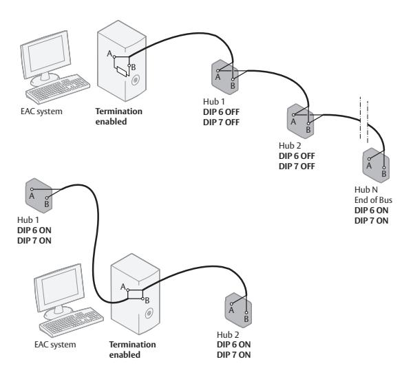
Communication Hub Connections, examples
Note: The RS485 bus cable should be of type twisted pair. The maximum cable length of 1000 meters should not be exceeded.
AH30 - RS485 Addressing
|
Add
ress |
A0 | A1 | A2 | A3 | A4* |
|---|---|---|---|---|---|
| 0 | Pairing Active* | ||||
| 1 | ON | ||||
| 2 | ON | ||||
| 3 | ON | ON | |||
| 4 | ON | ||||
| 5 | ON | ON | |||
| 6 | ON | ON | |||
| 7 | ON | ON | ON | ||
| 8 | ON | ||||
| 9 | ON | ON | |||
| 10 | ON | ON | |||
| 11 | ON | ON | ON | ||
| 12 | ON | ON | |||
| 13 | ON | ON | ON | ||
| 14 | ON | ON | ON | ||
| 15 | ON | ON | ON | ON |
Address examples
*) Note : If any of the A0-A4 DIP switches are moved from OFF to ON within 10 seconds from boot up and the Hub LED is lit, all paired devices will be unpaired.
|
Add
ress |
A0 | A1 | A2 | A3 | A4* |
|---|---|---|---|---|---|
| 16 | ON | ||||
| 17 | ON | ON | |||
| 18 | ON | ON | |||
| 19 | ON | ON | ON | ||
| 20 | ON | ON | |||
| 21 | ON | ON | ON | ||
| 22 | ON | ON | ON | ||
| 23 | ON | ON | ON | ON | |
| 24 | ON | ON | |||
| 25 | ON | ON | ON | ||
| 26 | ON | ON | ON | ||
| 27 | ON | ON | ON | ON | |
| 28 | ON | ON | ON | ||
| 29 | ON | ON | ON | ON | |
| 30 | ON | ON | ON | ON | |
| 31 | ON | ON | ON | ON | ON |
Address examples
*) A4 is only supported on AH30 in 1 - 1 mode.
AH20/AH30 - Communication Hub LED Indication
The Communication Hub has a single LED that supports an optical scheme with red, green and yellow. The indication scheme is described by the two figures below:
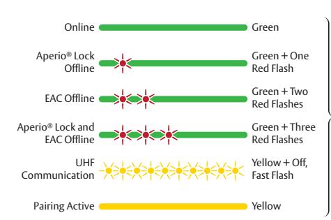
Note: With the software tool Aperio ® Programming Application and a USB radio dongle, further system installation parameters can be set.
| Physical Dimensions | 82 mm x 82 mm x 37 mm (H x W x T) |
|---|---|
| Power Supply | 8-24 VDC |
| Power Rating |
The power supply shall be able to deliver minimum
2 W (AH20 Advanced) alternatively 0.8 W (AH20 Standard and AH30) and be 3 A over current protected. Wire requirements 16-22 AWG. |
| Radio Standard |
IEEE 802.15.4 (2400 – 2483,5MHz)
16 channels (11-26) AES 128 bit encryption |
| Receiver Sensitivity | -100 dBm |
|
Wireless Transmit
Power |
10 dBm/MHz. Peak value from average detector
according to EN ETSI 300 328 Maximum spectral density. |
|
Wireless Operating
Range |
Indoors up to 25 m depending upon installed
environment. |
| Internal Antenna | Two cross polarized dipoles. |
| External Antenna |
One reverse polarity SMA external antenna connector.
AH20/30 is certified to be used with ASSA ABLOY external antenna AH-ANTENNA-1. If other external antenna is used it must be of same type (dipole) and not have larger antenna gain than 3.6 dBi. |
|
Operating
Temperature |
5 °C to 35 °C. |
| Humidity | < 95 % non-condensing. |
| IP Classification | IP20 |
|
Safety, Radio and
EMC |
IEC 62368-1:2014
EN 62368-1:2014 + A11:2017 UL/CSA 62368-1:2014 EN 301 489-1 V2.1.1 EN 301 489-17 V3.2.0 EN 300 328 V2.2.2 EN 50130-4:2011 + A1:2014 EN 62311 FCC 47CFR Part 15 subpart B and subpart C ISED RSS-247 and ICES-003 AS/NZS 4268 |
|
Number of
supported locks/ sensors |
AH20: 1
AH30:16 |
| NOTE | ||
|---|---|---|
The ASSA ABLOY Group is the global leader in access solutions. Every day we help people feel safe, secure and experience a more open world.

20
www.assaabloy.com/aperio