Allegion Connect Technical Manual 110380
Open the original PDF document
View PDF

Allegion Connect
Technical Manual
This manual covers the Allegion Connect products in multiple brands. See the table of contents to locate the desired brand information.
Contents
Overview
Wiring Harnesses
Von Duprin Products
- Electric Power Transfer: EPT-10
- RX/LX/RX-LX Exit Device
- QEL Exit Device
- QEL/(RX/LX/RX-LX) Exit Device
- EL Exit Device
- EL/(RX/LX/RX-LX) Exit Device
- CX (Chexit) Motor-Driven Exit Device
- ALK Exit Device
- E7500 Mortise Lock
- SS7500 Mortise Lock
- E996/M996 Trim
- 6100/6200 Series Electric Strikes
Falcon Products
- RX Exit Device
- MEL Exit Device
- MEL/RX Exit Device
- EL Exit Device
- EL/RX Exit Device
- EA (Exit Alarm) Exit Device
- T-Series Electrified Locks (T851/T881)
- T851/T881 (12 VDC)
- T851/T881 (24 VDC)
- MA-Series Electrified Locks (MA851/MA881)
- MA851/MA881 (12 and 24 VDC)
Schlage Products
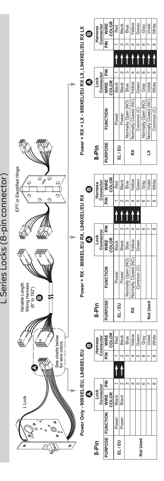
- L Series Locks (8-pin connector)
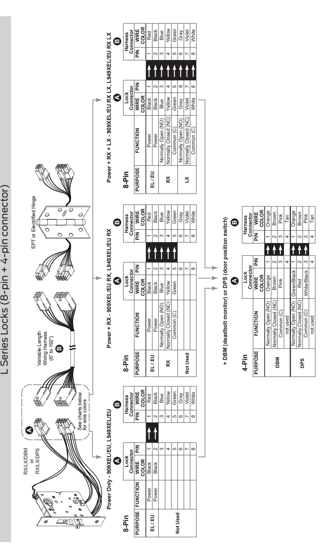
- L Series Locks (8-pin + 4-pin connector)
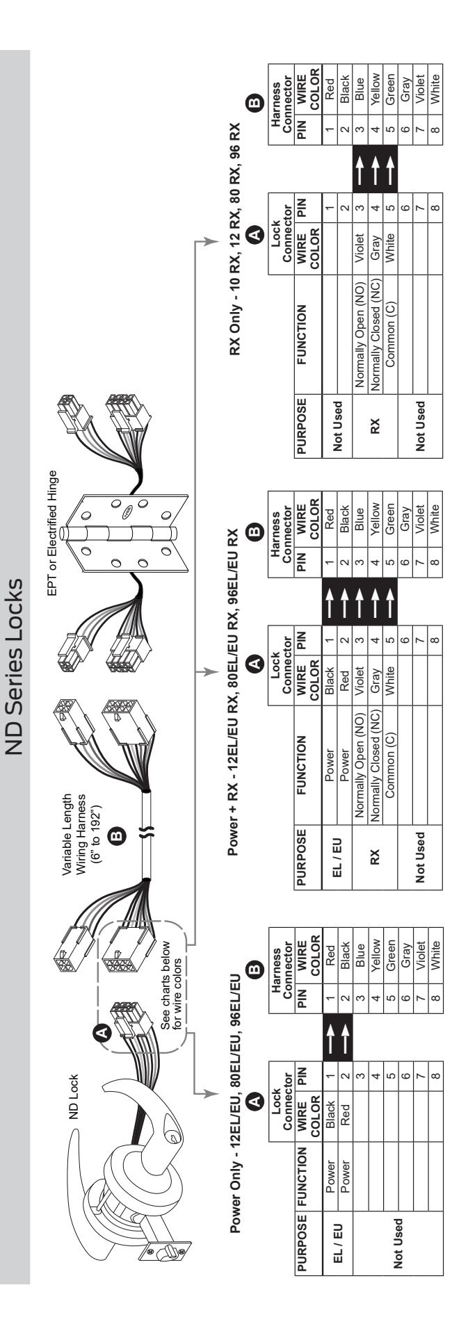
- ND Series Locks
Ives Products
- 3CB1/5BB1 TW/TWM Architectural Hinge
- 700-TW8/700CS-TWP Continuous Hinge
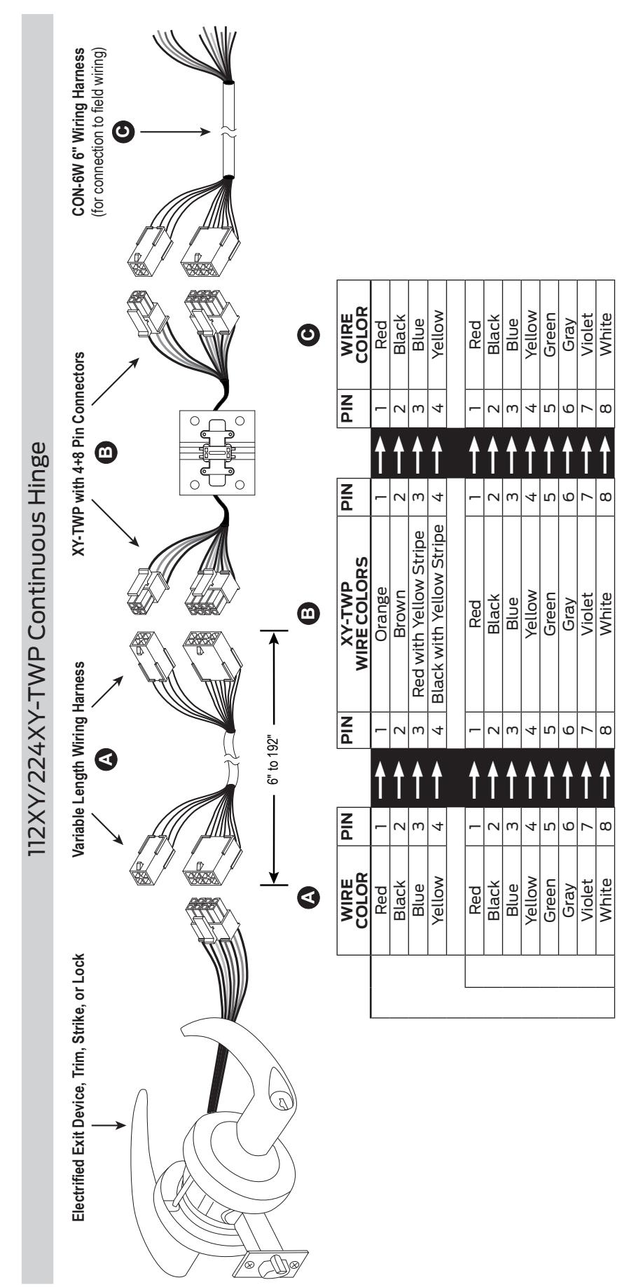
- 112XY/224XY-TWP Continuous Hinge
- Intermediate and Pocket Pivots
Connector Kit
Extraction Tool
Overview
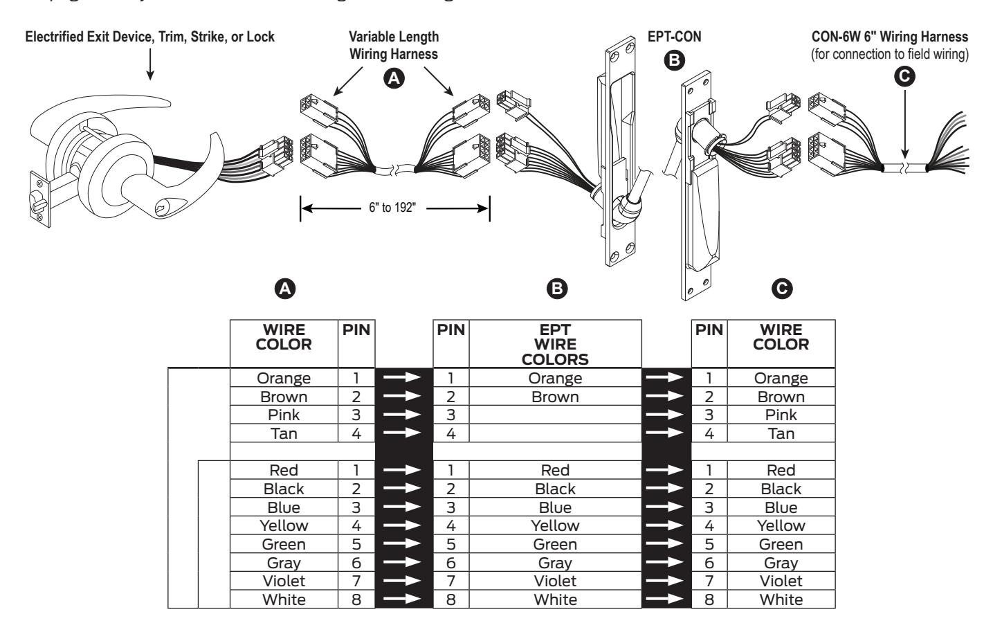
Electrified Hardware
The electrified exit device, lock, trim, or strike is supplied with the Allegion Connect 8 pin and/or 4 pin connectors. In some cases an adapter is supplied and is shown in greater detail on the application pages of this manual. There are limitations regarding what Allegion Connect products can be combined. Consult factory for combinations not shown in this manual.
EPT or Hinge
The EPT or electrified hinge is supplied with Allegion Connect 8 pin and 4 pin connectors, or 8 pin connector only. See related product page.
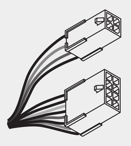
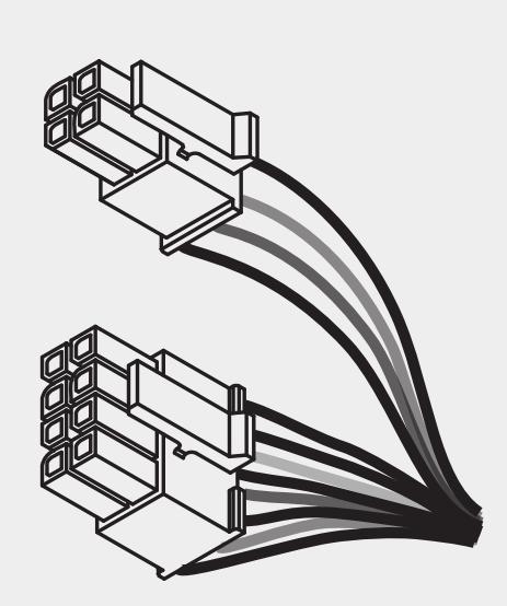
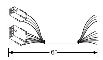
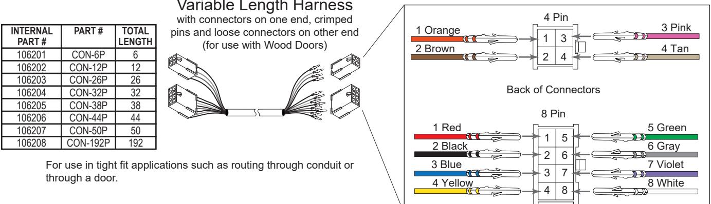
Variable Length Wiring Harnesses
The 20 gauge wiring harnesses have Allegion Connect 8 pin and 4 pin connectors on each end, or can be ordered with the connectors on one end only. One wiring assembly is used to connect the electrified hardware to the EPT/hinge, and a 6" CON-6W wiring harness can be used to route from the EPT/hinge to field wiring.
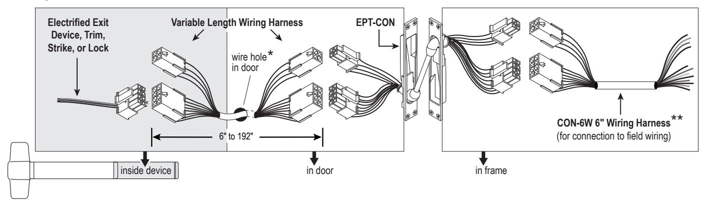
* Standard wiring hole may need to be enlarged slightly to fit connector through door surface.
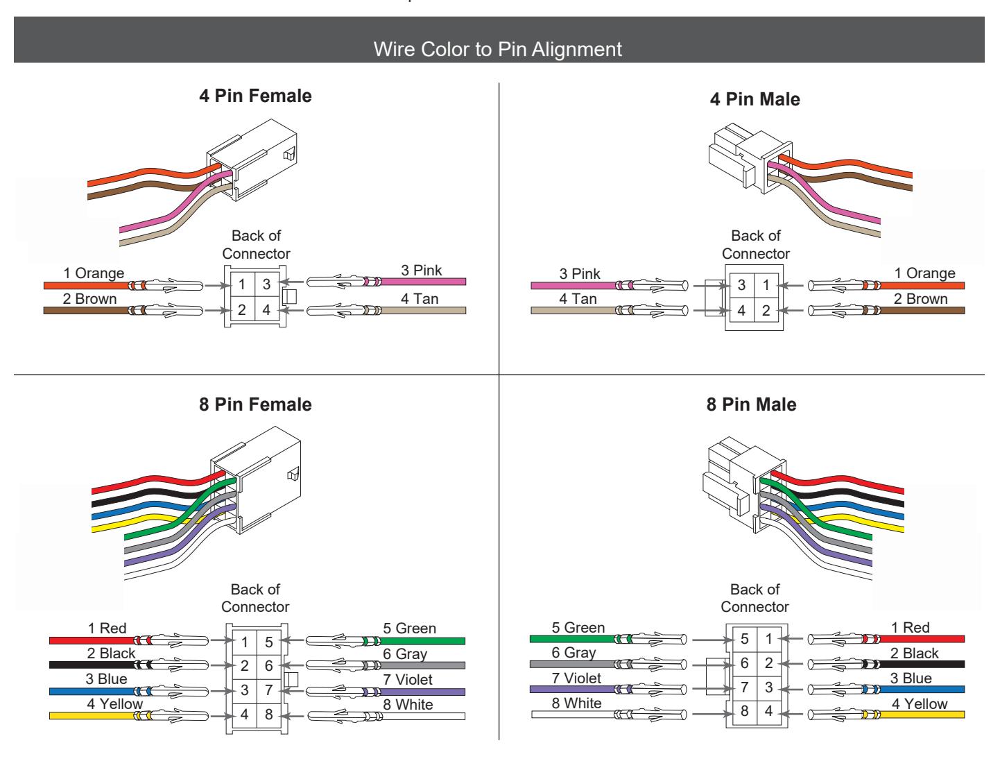
Wiring Harnesses
INTERNAL
PART#
106210
PART#
TOTAL
ENGTH
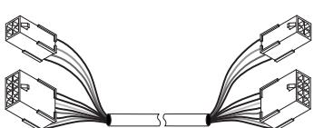
Variable Length Harness
with connectors on both ends (for use with Hollow Metal Doors)
|
INTERNAL
PART # |
PART# |
TOTAL
LENGTH |
|---|---|---|
| 106190 | CON-6 | 6 |
| 106191 | CON-12 | 12 |
| 106192 | CON-26 | 26 |
| 106193 | CON-32 | 32 |
| 106194 | CON-38 | 38 |
| 106195 | CON-44 | 44 |
| 106196 | CON-50 | 50 |
| 106197 | CON-192 | 192 |
6" Harness**
6" with connectors on one end only (for connection to field wiring)
| 32 | CON-32 | 5193 | |
| 38 | CON-38 | 6194 | |
| 44 | CON-44 | 3195 | |
| 50 | CON-50 | 6196 | |
| 192 | CON-192 | 6197 | |
| Variable Length Harr |
** Stripped leads of CON-6W connect to field wiring. Field wiring from frame to power supply must be appropriate gauge (Variable Length Harnesses have 20 gauge wire and are not acceptable). Refer to wire gauge specifications in instructions for the particular electrified hardware.
Electric Power Transfer: EPT-10
See page 3 for system overview and wiring harness usage.
NOTE: Field wiring from frame to power supply must be appropriate gauge. Refer to wire gauge specifications in instructions for the particular hardware.
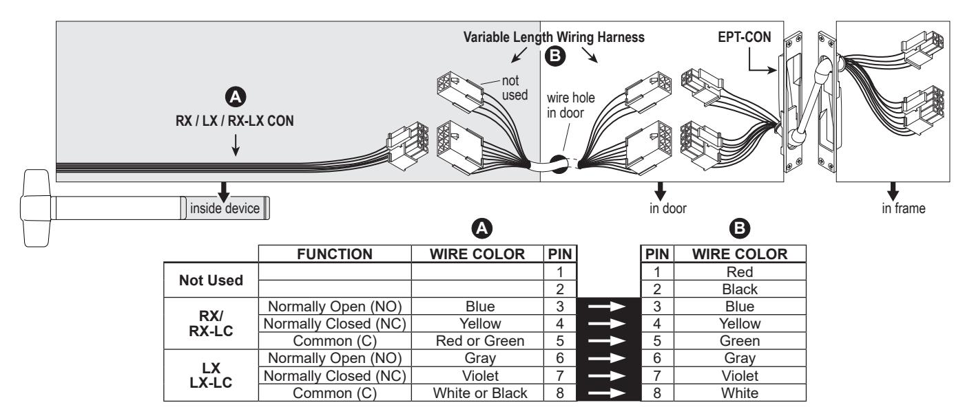
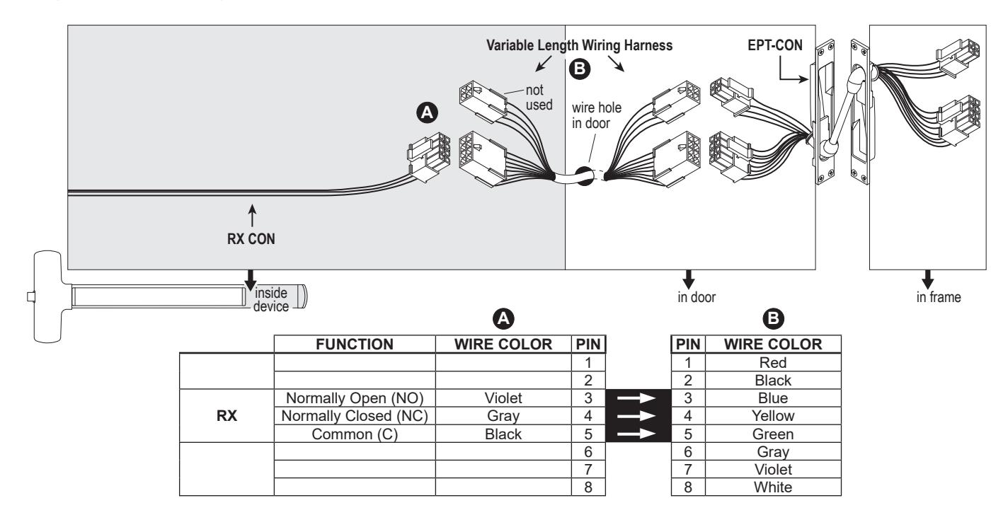
RX/LX/RX-LX Exit Device
QEL Exit Device
See page 3 for system overview and wiring harness usage. Colors shown below at wiring harness should remain consistent throughout the EPT or hinge and harness outside of frame.
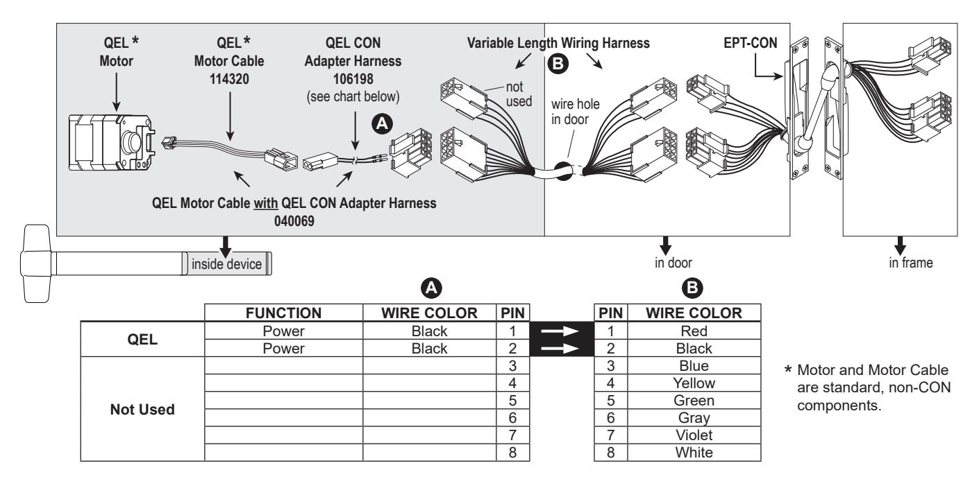
NOTE: The 6' cable (110388) that is furnished with standard QEL devices is not furnished or required for CON applications.
QEL/(RX/LX/RX-LX) Exit Device
See page 3 for system overview and wiring harness usage. Colors shown below at wiring harness should remain consistent throughout the EPT or hinge and harness outside of frame.
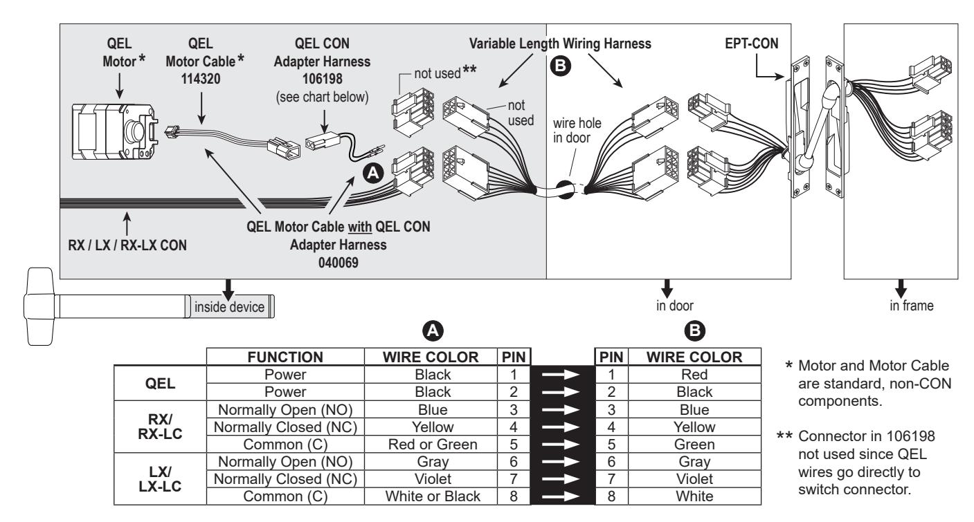
NOTE: The 6' cable (110388) that is furnished with standard QEL devices is not furnished or required for CON applications.
EL Exit Device
See page 3 for system overview and wiring harness usage. Colors shown below at wiring harness should remain consistent throughout the EPT or hinge and harness outside of frame.
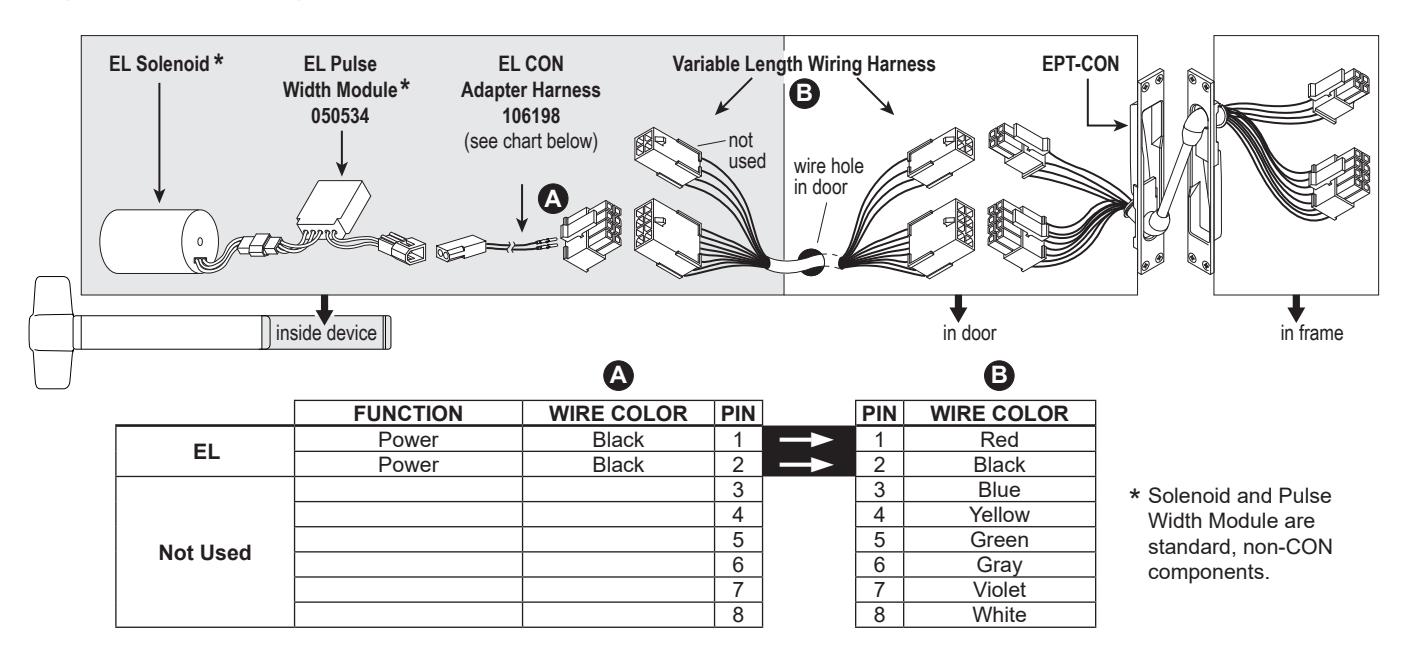
NOTE: The 6' cable (110388) that is furnished with standard EL devices is not furnished or required for CON applications.
EL/(RX/LX/RX-LX) Exit Device
See page 3 for system overview and wiring harness usage. Colors shown below at wiring harness should remain consistent throughout the EPT or hinge and harness outside of frame.
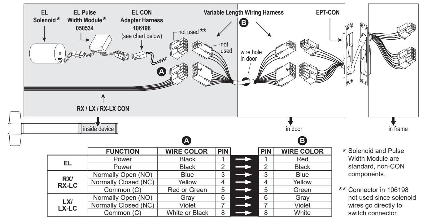
NOTE: The 6' cable (110388) that is furnished with standard EL devices is not furnished or required for CON applications.
CX (Chexit) Motor-Driven Exit Device
See page 3 for system overview and wiring harness usage. Colors shown below at wiring harness should remain consistent throughout the EPT or hinge and harness outside of frame.
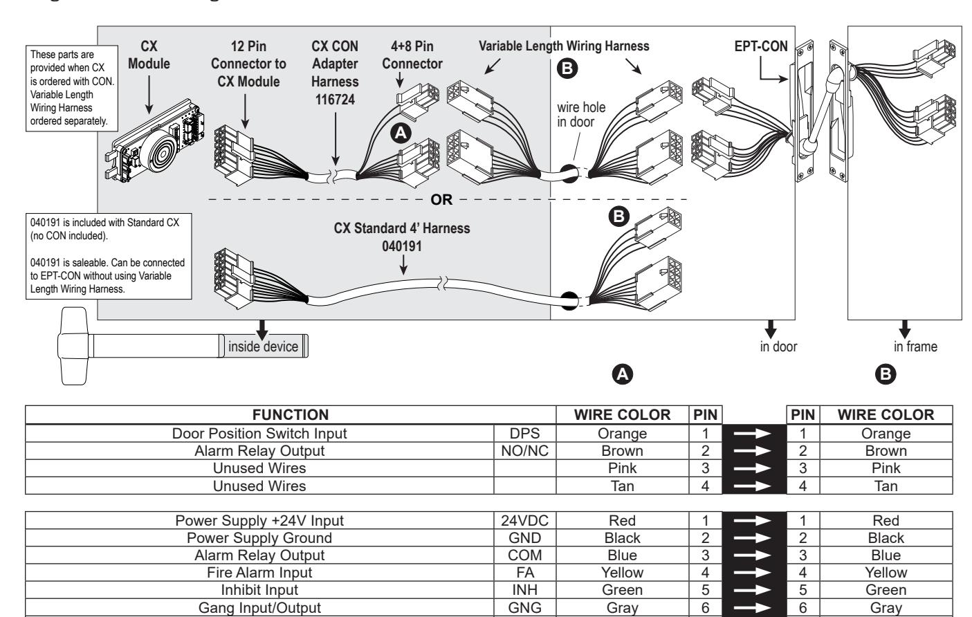
NO/NC
COM
Violet
White
8
Secure Relay Output
Secure Relay Output
Violet
White
8
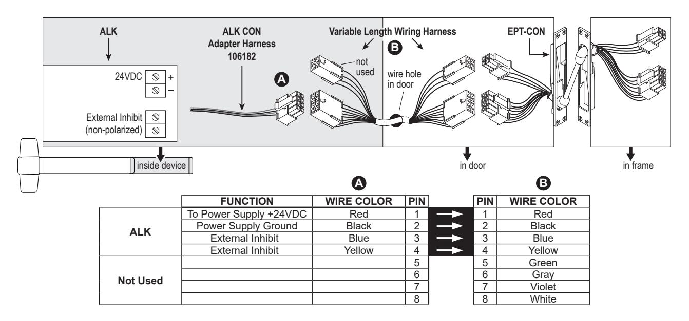
ALK Exit Device
See page 3 for system overview and wiring harness usage. Colors shown below at wiring harness should remain consistent throughout the EPT or hinge and harness outside of frame.
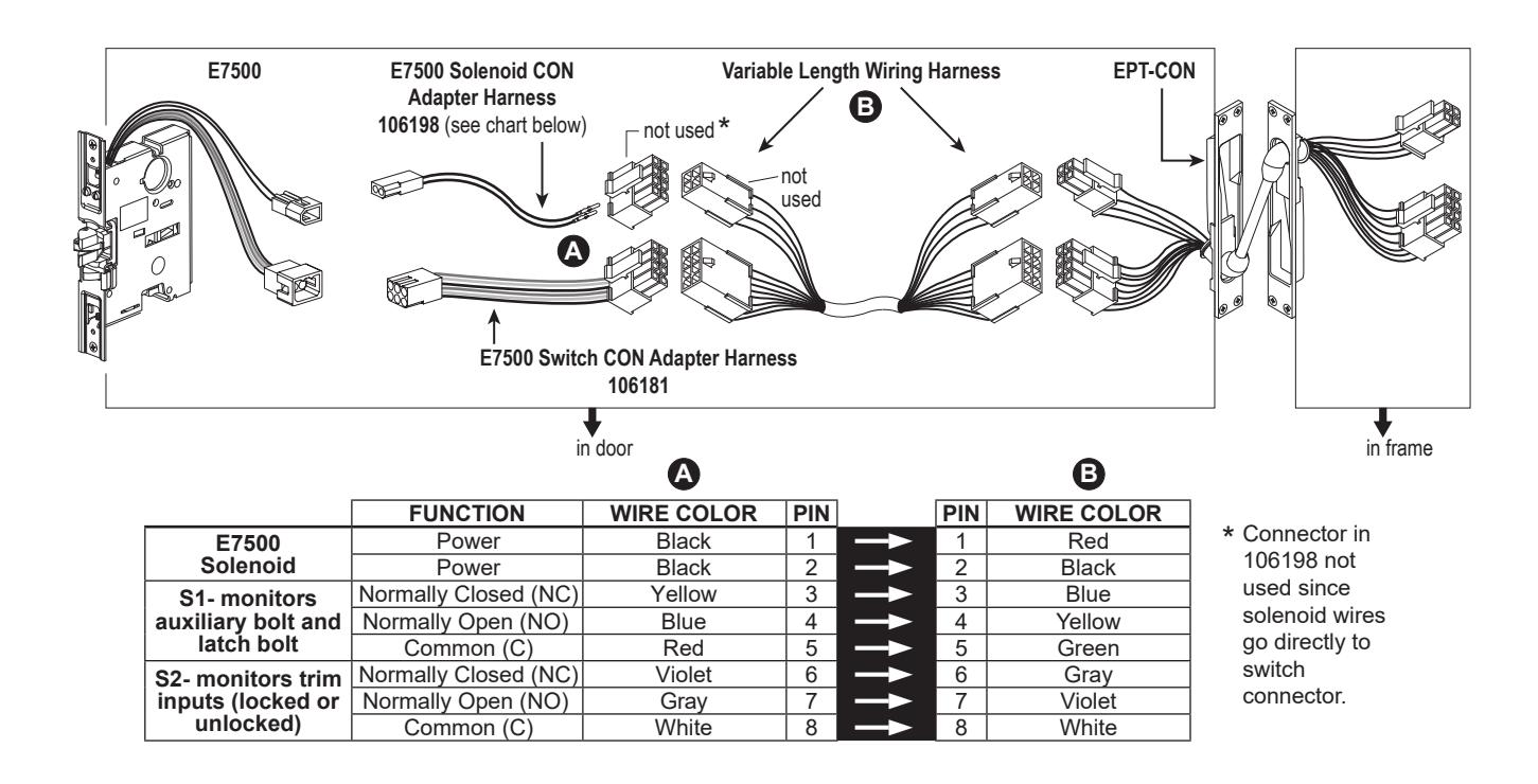
E7500 Mortise Lock
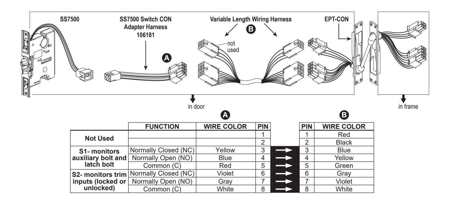
SS7500 Mortise Lock
See page 3 for system overview and wiring harness usage. Colors shown below at wiring harness should remain consistent throughout the EPT or hinge and harness outside of frame.
E996/M996 Trim
See page 3 for system overview and wiring harness usage. Colors shown below at wiring harness should remain consistent throughout the EPT or hinge and harness outside of frame.
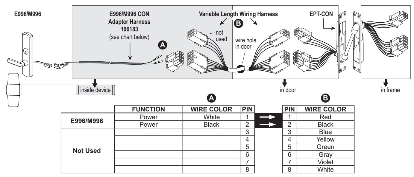
NOTE: The Cable.10038 that is furnished with standard E996/M996 trim is not furnished or required for CON applications.
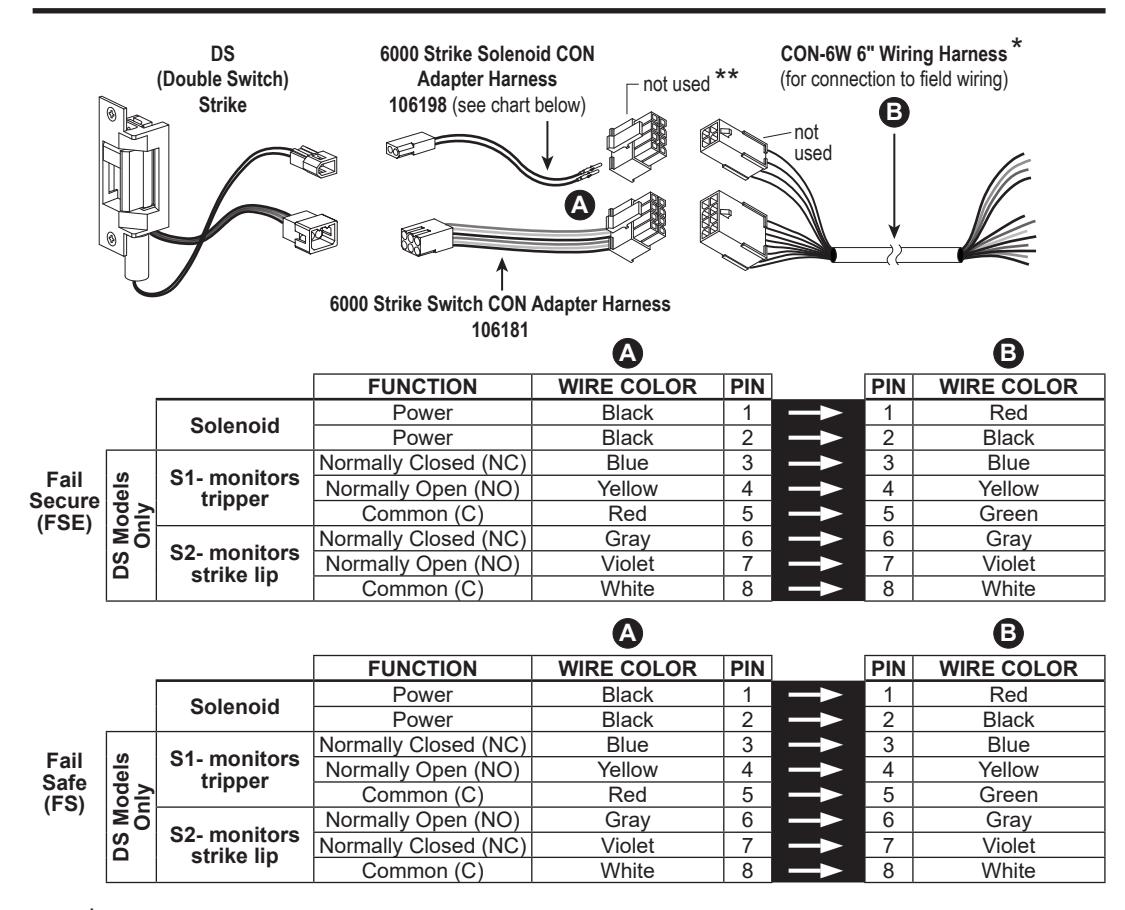
6100/6200 Series Electric Strikes
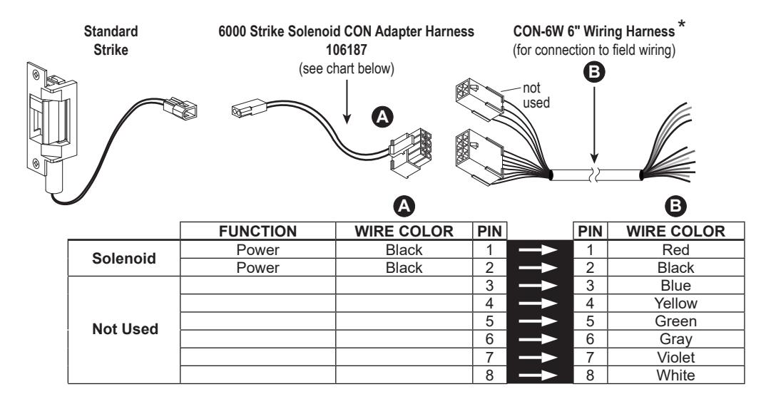
* 6& quot; harness is for single door application. For double door application, specify variable length harness to connect electric strike to power transfer.
* 6& quot; harness is for single door application. For double door application, specify variable length harness to connect electric strike to power transfer.
** Connector in 106198 not used since solenoid wires go directly to switch connector.
RX Exit Device
MEL Exit Device
See page 3 for system overview and wiring harness usage. Colors shown below at wiring harness should remain consistent throughout the EPT or hinge and harness outside of frame.
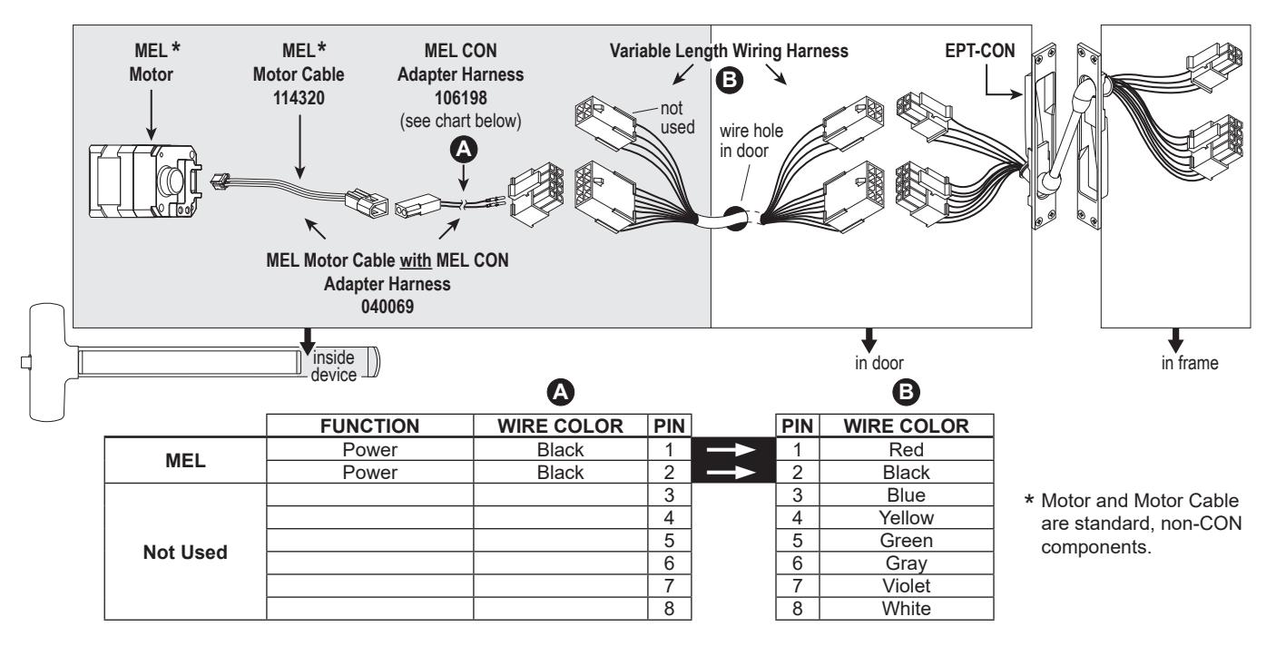
NOTE: The 6' cable (110388) that is furnished with standard EL devices is not furnished or required for CON applications.
MEL/RX Exit Device
See page 3 for system overview and wiring harness usage. Colors shown below at wiring harness should remain consistent throughout the EPT or hinge and harness outside of frame.
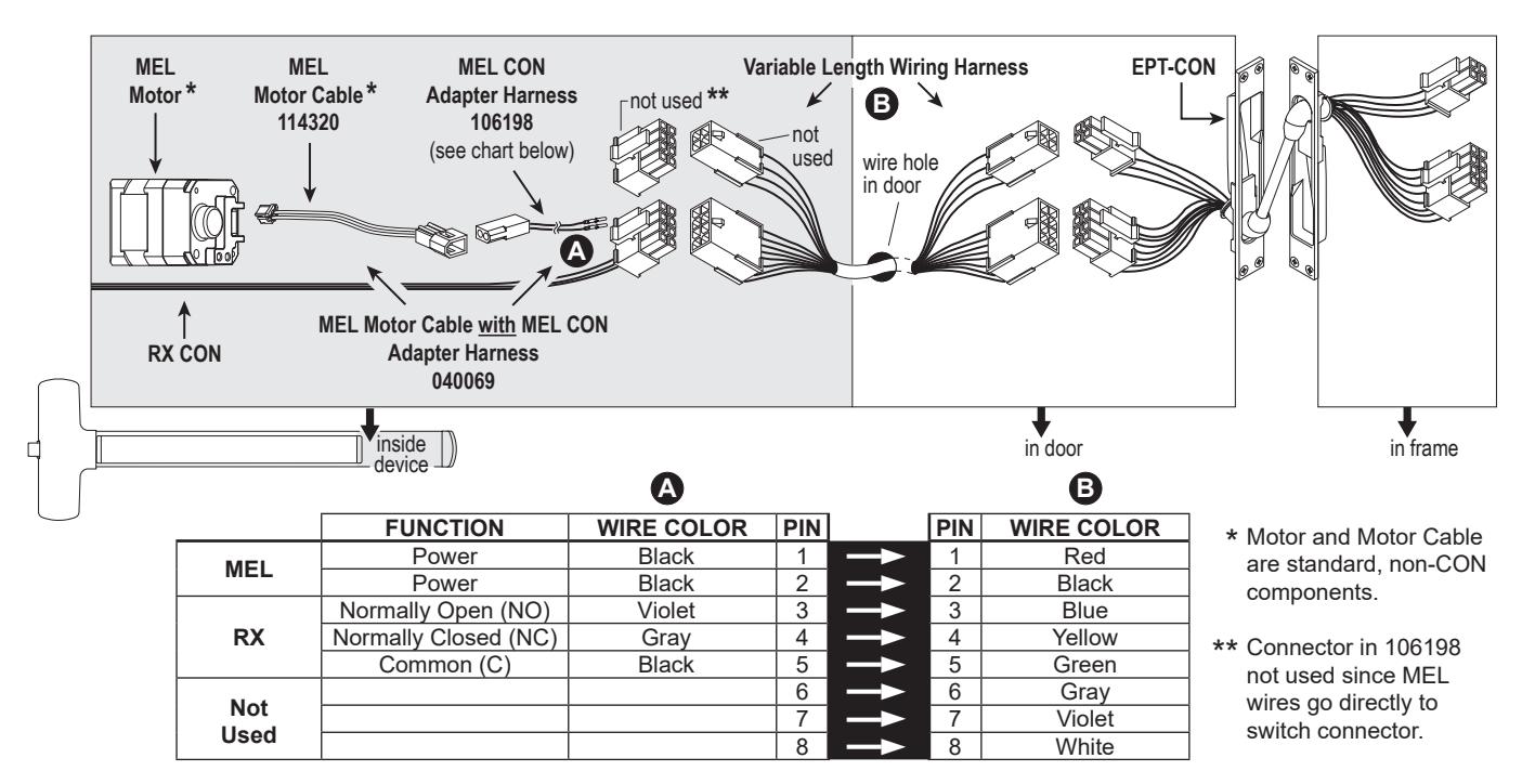
NOTE: The 6' cable (47269206) that is furnished with standard MEL devices is not furnished or required for CON applications.
EL Exit Device
See page 3 for system overview and wiring harness usage. Colors shown below at wiring harness should remain consistent throughout the EPT or hinge and harness outside of frame.
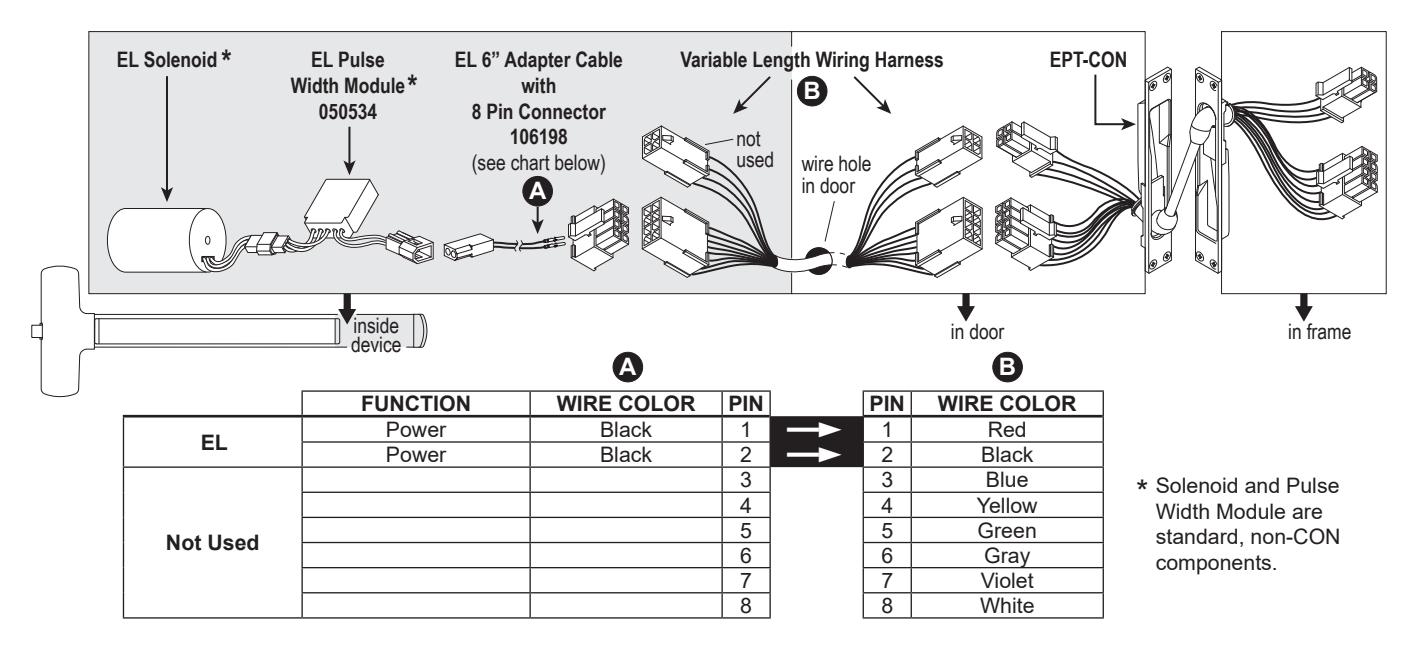
NOTE: The 6' cable (110388) that is furnished with standard EL devices is not furnished or required for CON applications.
EL/RX Exit Device
See page 3 for system overview and wiring harness usage. Colors shown below at wiring harness should remain consistent throughout the EPT or hinge and harness outside of frame.
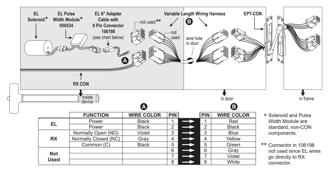
NOTE: The 6' cable (110388) that is furnished with standard EL devices is not furnished or required for CON applications.
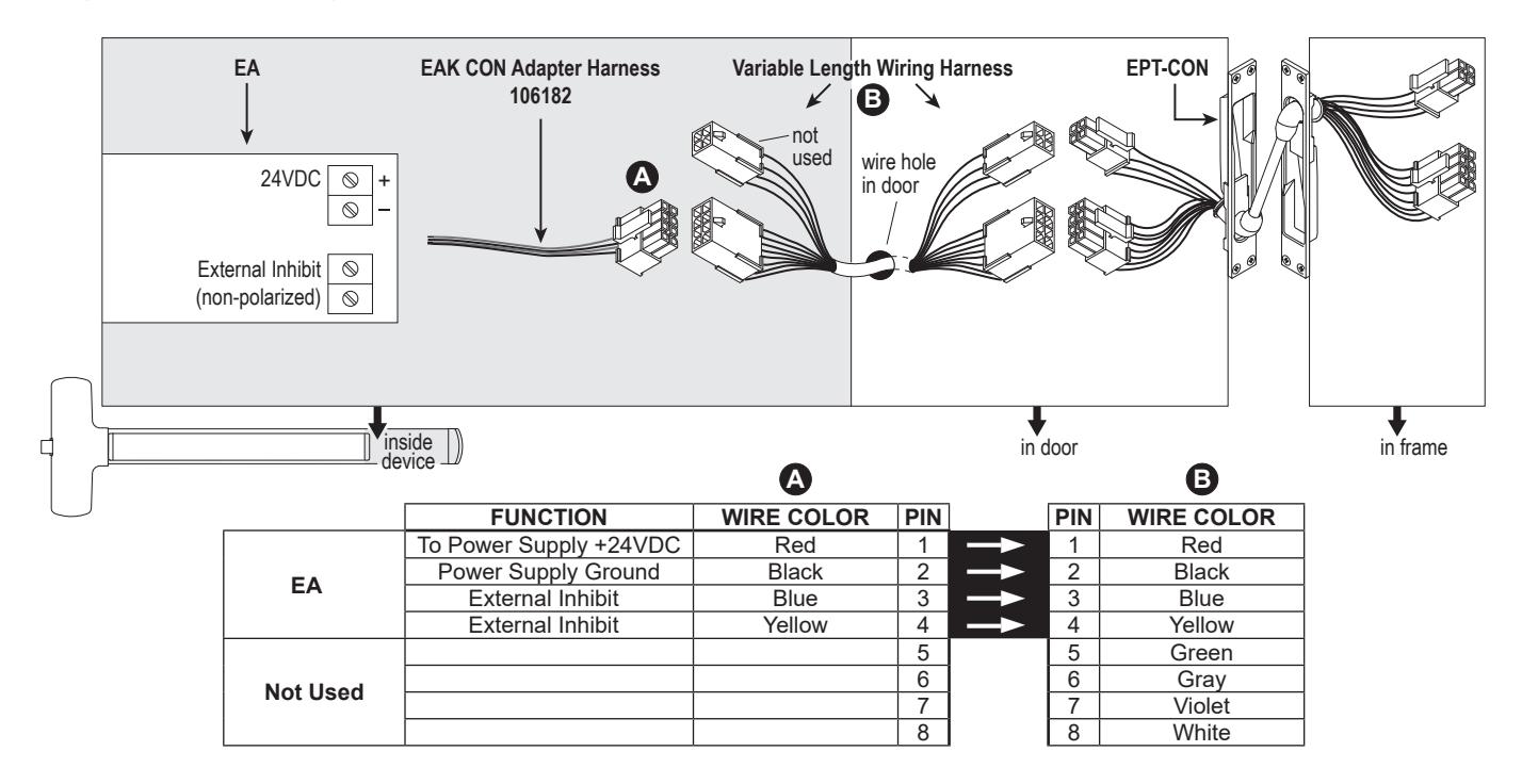
EA (Exit Alarm) Exit Device
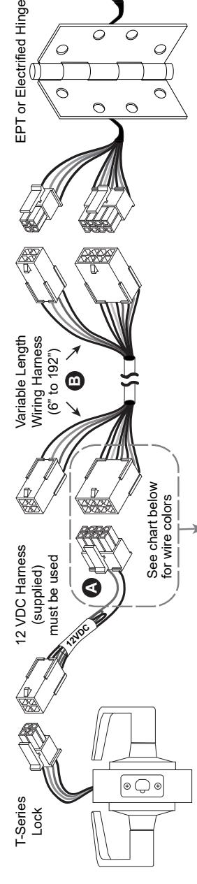
T-Series Electrified Locks (T851/T881)
Electrical Specifications: Fail Safe/Fail Secure .65 AMP @ 12 VDC .32 AMP @ 24 VDC T851 Storeroom Fail Safe: Deadlocking latch bolt operated by lever from either side, except when outer lever is electrically locked. When outer lever is locked (inoperable), latch bolt retracted by key in cylinder outside. Inside lever is always free.
T881 Storeroom Fail Secure:
Deadlocking latch bolt operated by lever inside at all times. Outside lever is inoperable until electrically unlocked, then latch bolt is operable from either side. When outside lever is inoperable, latch bolt retracted by key in cylinder outside.
T851/T881 (12 VDC)
12 VDC Configuration Shown

|
Connector
Harness |
COLOR
WIRE |
Red | Black | Blue | Yellow | Green | Gray | Violet | White |
|---|---|---|---|---|---|---|---|---|---|
| PIN | 1 | 2 | 3 | 4 | 5 | 6 | 7 | 8 | |
| -> | -> | ||||||||
| PIN | 1 | 2 | 3 | 4 | 5 | 6 | 7 | 8 | |
|
Connector
Lock |
COLOR
WIRE |
Red | Black | ||||||
| FUNCTION | Power | Power | |||||||
| PURPOSE | EL / EU | Not Used | |||||||
EPT or Electrified Hinge
24 VDC Configuration Shown
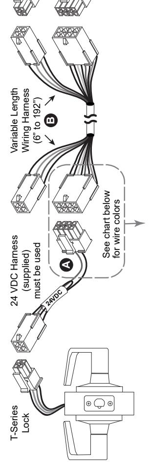
Power Only - T851, T881
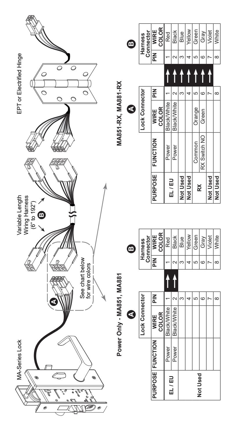
MA-Series Electrified Lock
Electrical Specifications:
Fail Safe/Fail Secure .65 AMP @ 12 VDC .32 AMP @ 24 VDC
MA851 Storeroom Fail Safe/Electrified EL:
Latch bolt operated by knob/lever from either side except when outer knob/lever is electrically locked. When outer knob/lever is locked, latch bolt retracted by key in cylinder outside. Deadlocking latch. Inside knob/lever always free for immediate egress. Specify 12 or 24 VDC.
MA881 Storeroom Fail Secure/Electrified EU:
Latch bolt operated by knob/lever from inside except when outer knob/lever is electrically unlocked, then latch bolt from either side. When locked, key in cylinder outside retracts latch bolt. Deadlocking latch. Inside knob/lever always free for immediate egress. Specify 12 or 24 VDC.
MA851/MA881 (12 and 24 VDC)
12 VDC Configuration (2 Black Power Wires) 24 VDC Configuration (2 White Power Wires)
3CB1/5BB1 TW/TWM Architectural Hinge
The TW4 MON, TW8 MON, and TW12 Electrified Hinges are supplied with Allegion Connect 8 pin and 4 pin connectors. The TW4 and TW8 Electrified Hinges are supplied with Allegion Connect 8 pin connectors.
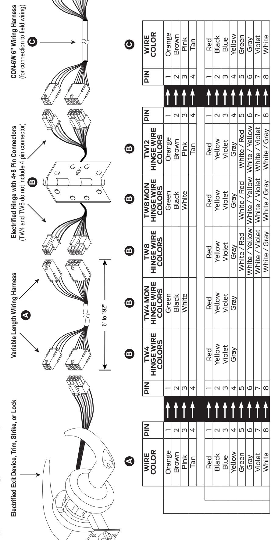
NOTE: Field wiring from frame to power supply must be appropriate gauge. Refer to wire gauge specifications in instructions for the particular hardware.
700-TW8/700CS-TWP Continuous Hinge The 700-TW8 is supplied with Allegion Connect 8 pin connectors. The 700CS-TWP is supplied with Allegion Connect 8 pin and 4 pin connectors.
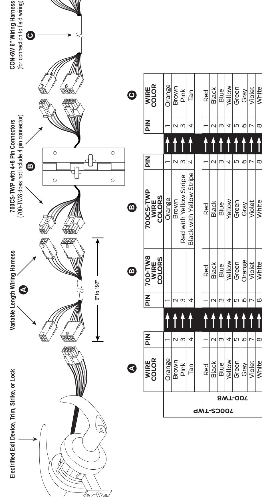
NOTE: Field wiring from frame to power supply must be appropriate gauge. Refer to wire gauge specifications in instructions for the particular hardware.
NOTE: Field wiring from frame to power supply must be appropriate gauge. Refer to wire gauge specifications in instructions for the particular hardware.
Intermediate and Pocket Pivots The TW4 and TW8 Electrified Pivots are supplied with Allegion Connect 8 pin connectors.
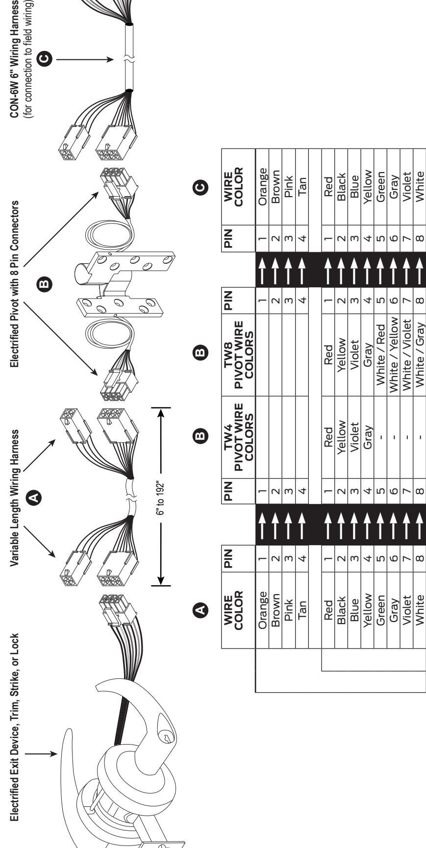
NOTE: Field wiring from frame to power supply must be appropriate gauge. Refer to wire gauge specifications in instructions for the particular hardware. NOTE: Applies for 7215/7226/7227 PT INT, 7215F/7226F/7227F PT INT, 7230F/7237F PT INT, E91105F.
Connector Kit
Included in Kit (CON-KIT 050823):
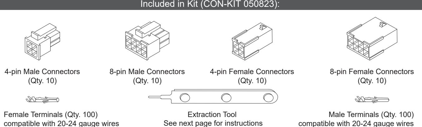
Not Included in Kit:
Crimping Tool Can be purchased elsewhere (Molex part number 63819-0000) This will be required to install terminals on loose wires
Extraction Tool Instructions
1 Insert extractor tool tip into front of connector on either side of the terminal until it stops.
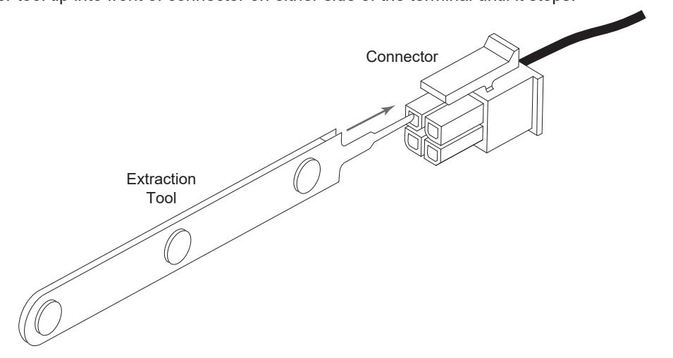
- 2 Rotate tool clockwise then counter-clockwise approximately 25º to 30º in each direction, once or twice.
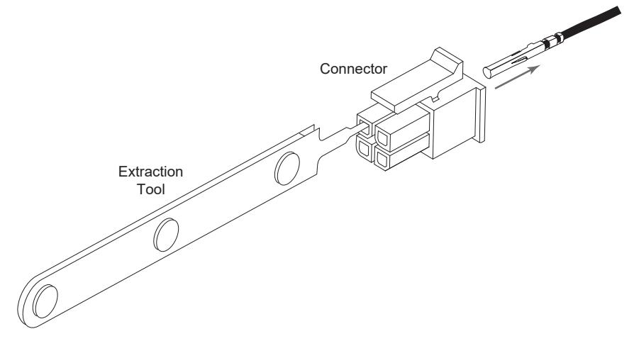
- 3 Repeat steps 1 and 2 on the opposite side of terminal until tabs are bent down.

4 Pull wire out of back of connector housing.
NOTE: Removal damages the terminal locking tangs. The terminal is not reusable.
About Allegion
Allegion (NYSE: ALLE) creates peace of mind by pioneering safety and security. As a $2 billion provider of security solutions for homes and businesses, Allegion employs more than 8,000 people and sells products in more than 120 countries across the world. Allegion comprises 27 global brands, including strategic brands CISA®, Interflex®, LCN®, Schlage® and Von Duprin®.
For more, visit www.allegion.com .