Alarmed Exit Options (91, 92, 93, 94- Prefixes)
Open the original PDF document
View PDFSARGENT INSTRUCTIONS FOR ALARMED EXIT OPTIONS
on 5100 and 5800
FOR ASSISTANCE, CONTACT SARGENT AT 800-727-5477 or www.sargentlock.com
91 Prefix
- Remote Power Source
- Refer to drawing for circuit board connections (pins 11, 12) and wire colors
- DC wiring must be as short as possible, avoiding major electrical noise sources. Although 8' of wire is provided, additional 22 gauge wire may be spliced between connectors.
- Internal battery power should be maintained in case of 110VAC power failure
- Use model 3267 Power Supply (rated 9VDC, 700ma)
- 110VAC wiring for hard-wired power source should return direct as possible to main source avoiding major electrical noise sources
92 Prefix
- Remote Monitor Interface
- Refer to drawing for circuit connections (pins 10, 11, 12) and wire colors
- Electrical specifications
pin 10 alarm status
standby mode - open circuit (end of line termination to be specified by customer) alarm mode - 250ma current switch to ground when low frequency horn sounds
pin 11 circuit ground
pin 12 remote power, positive voltage
93 Prefix
- Continuous Alarm
- Normal 2 minute alarm cycle shut-off is eliminated. Alarm cycle must be terminated by a clockwise key operation
94 Prefix
- Automatic Re-arming
Alarm cycle is terminated by a clockwise key operation. Alarm is automatically re-armed 20 seconds after key is returned to withdraw position
- 1) Remote switch
- 2)
- 3) Sensor bolt
- 4) Roller switch
- 5) Reset
- 6)
- 7) HF horn
- 8)
- 9) Not used
- 10) Alarmed status blue wire (92)
- 11) Ground black wire (91 & 92)
- 12) +9 volt input red wire (91)
- 13) Ground black wire (battery)
- 14) +9 volt input red wire (battery)
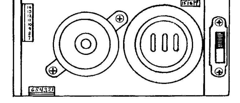
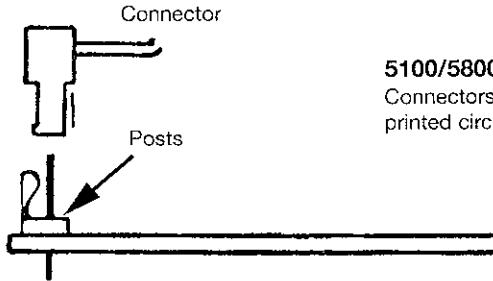
5100/5800 Circuit Board Connections
Connectors are directional and must be installed as illustrated. Wires are to be routed under the printed circuit board and through the access hole of the back plate.
SARGENT®
5100 and 5800 Exit Alarm Parts
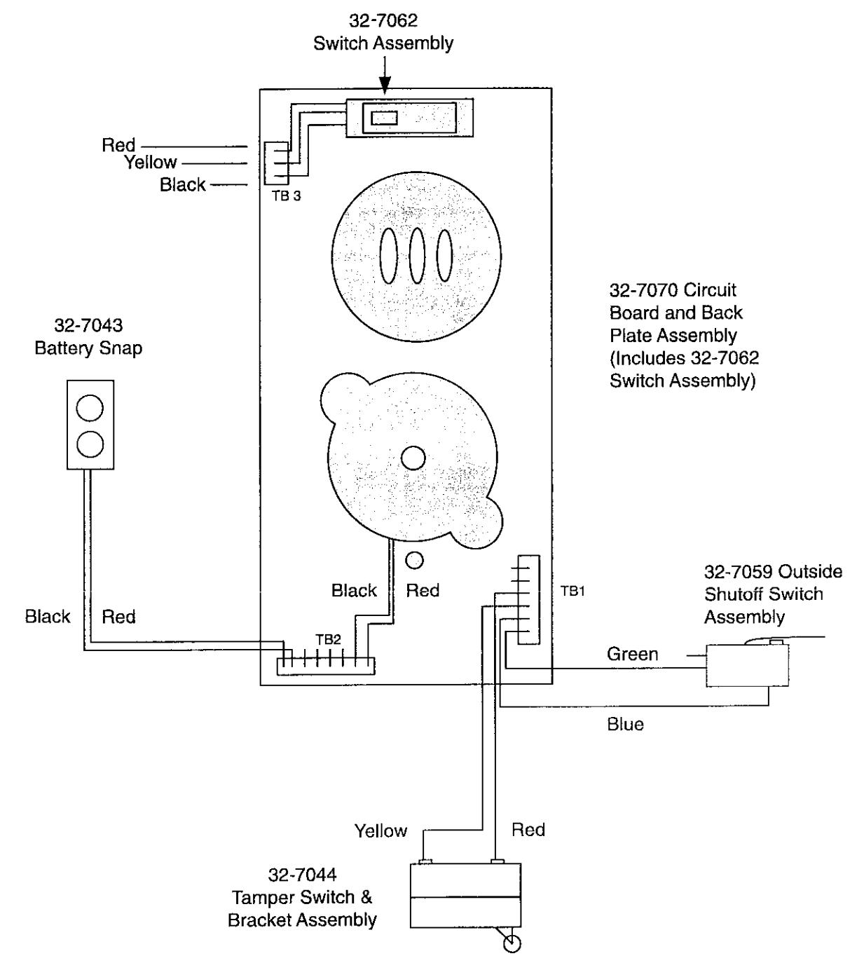
Important: To prevent damaging the Tamper Switch while installing or removing cover, depress push rail or paddle to fully retract latchbolt.
Notes:
Consult factory for other replacement parts not shown here.
Not all parts or assemblies are user serviceable. For additional information, contact SARGENT:
Customer Service
800-727-5477
Electrical Technical Support
800-810-WIRE (9473) www.sargentlock.com
Web site
5100/5800 Rev. A 04/03