Alarm Lock PDL6300 Installation Instructions
Open the original PDF document
View PDF

345 Bayview Avenue, Amityville, New York 11701 For Sales and Repairs 1-800-ALA-LOCK For Technical Service 1-800-645-9440 or visit us at <a href="https://tech.napcosecurity.com/">https://tech.napcosecurity.com/</a> Technical Service is for security professionals Publicly traded on NASDAG Symbol: NSSC
© ALARM LOCK 2018
Trilogy Networx ™ Double-Sided PDL6300 Installation Instructions
WI2294LF 1/18
GENERAL DESCRIPTION
This double-sided stand-alone door lock provides controlled entry and exit at locations such as airport security areas and police stations. The PDL6300 fully supports Version 2 Gateways and Expanders and features an HID compatible ProxCard® reader, and a real-time clock/ calendar that automatically adjusts for Daylight Saving Time and allows for automated programming of events.
Double-Sided Description
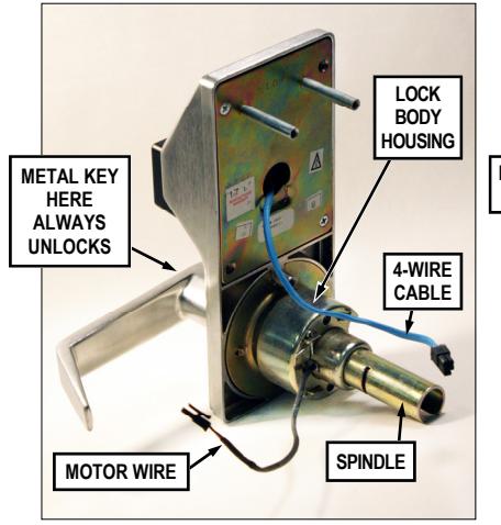
Both sides of the lock contain keypads, keyholes, levers and proximity readers. To differentiate between the two sides of the lock, these instructions refer to the "Primary" side and the "Secondary" side. The Primary side has the Lock Body Housing attached; inserting the metal key into the Primary side lock cylinder will always unlock the latch, allowing entry or exit. The Secondary side contains the battery; inserting the metal key into its lock cylinder will NEVER unlock the latch. The key inserted into the Secondary side ONLY allows secure removal / installation of the Secondary side Lever. Note: To remove the Secondary side Lever, the metal key must be used to allow the Lever Catch to be depressed.
"PRIMARY SIDE"
"SECONDARY SIDE"
Important: Because the radio antenna is located in the front of the Primary housing, the lock should be installed with the Primary side facing the Gateway for the best radio range.
DOOR PREPARATION
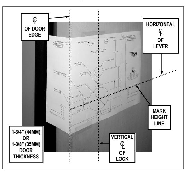
FIG. 1: FOLD AND PLACE TEMPLATE ON DOOR
- 1. Fold and place template on high edge of door at the recommended height from floor. See Fig. 1.
- 2. Mark hole centers on door and door edge.
- 3. Drill 3/8" thru-bolt holes first, then drill 2-1/8" hole.
For Hardwood Doors:
Notch on both sides of 2-1/8" hole to accommodate Mounting Plate tabs.
MAIN PROCEDURES GENERAL DESCRIPTION ..... DOOR PREPARATION...... 1 INSTALLATION JIG......2 I ATCH INSTALLATION ..... STRIKE INSTALLATION ..... LOCK PREPARATION......2 ADJUSTING FOR DOOR THICKNESS.......3 TO REVERSE LEVER HANDING .................................... LOCK INSTALLATION ......3-5 INTERCHANGEABLE (IC) LOCKS......5 INSTALL INTERCHANGEABLE (IC) CORES ......5 CHANGING AN EXISTING IC CORE...... 6 REMOVING THE IC CORE & LEVER......6 PROGRAMMING......6 TROUBLESHOOTING......6 WIRE CONNECTIONS ......7 NAPCO LIMITED WARRANTY ......8
For Hollow Metal Doors:
Requires horizontal and vertical lock and latch case support (provided by door manufacturer).
IMPORTANT: Be sure to remove all metal burrs from connector cable hole-- sharp edges will eventually wear away wire insulation .
4. Drill all remaining holes in template as required.
INSTALLATION JIG
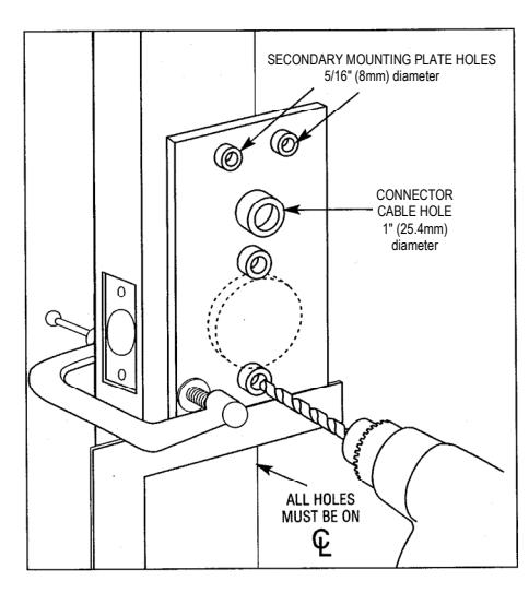
FIG. 2: ALARM LOCK INSTALLATION JIG
- 1. If 2-1/8" hole already exists, use optional Alarm Lock Installation Jig to ensure accurate locating and drilling of 3/8" and 5/16" thru-bolt holes.
- 2. For best results, align the Installation Jig to door with a square and clamp to door before drilling. See Fig. 2.
LATCH INSTALLATION
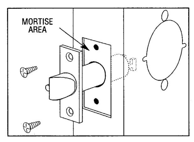
FIG. 3: LATCH INSTALLATION
- 1. Drill 1" diameter hole for latch.
- 2. Mortise for latch front. Insert latch and fasten with two screws supplied.
Note: It is important that both 1" and 2-1/8" holes be on the same horizontal center line.
STRIKE INSTALLATION
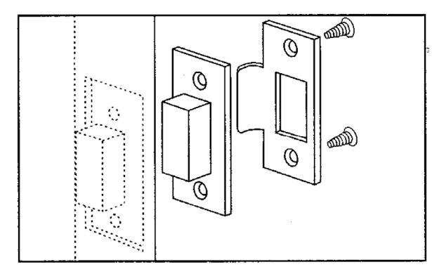
FIG. 4: STRIKE INSTALLATION
- 1. Align strike with latch.
- 2. Trace strike outline on door jamb.
- 3. Mortise jamb and install dust box and strike.
LOCK PREPARATION
From the factory, the Primary and Secondary sides of the lock are attached together. Separate the Secondary from the Primary side as follows:
- 1. Insert the metal key into the Secondary side lock cylinder (the Secondary side has the 2 mounting thru-bolt holes, as shown in Fig. 5). Turn the key 45° (either direction).
- 2. See Fig. 5 and 6. Insert the Lever Release Pin through the oval hole located in the Secondary side housing and through the small round hole in the Lever. While depressing the Lever Catch, pull off Lever. See Fig. 6 for an image of the Lever Catch.
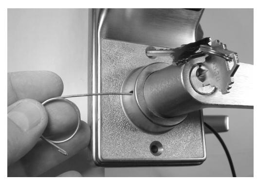
FIG. 5: INSERT LEVER RELEASE PIN
3. Depressing this Lever Catch also allows the Secondary side to be separated from the Primary side. Use a small screwdriver to depress the Lever Catch and pull the Secondary lock housing away from the Primary side. See Fig. 6.
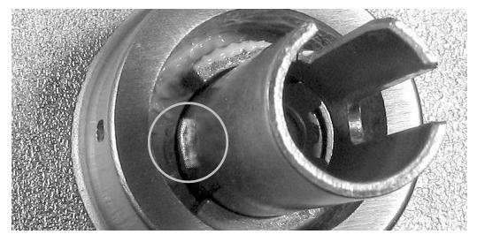
FIG. 6: LEVER CATCH (circled)
ADJUSTING FOR DOOR THICKNESS
Plastic spacers either add or subtract the distance between the roses. Each spacer represents 1/8" of door thickness. Locks are factory assembled for 1-3/4" thick doors using 3 plastic spacers.
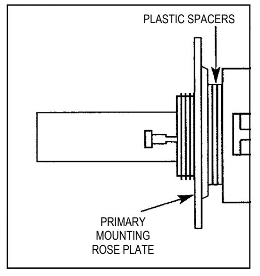
FIG. 7: ADJUST DOOR THICKNESS
For other door thicknesses:
- 1. Remove Primary side Lever by inserting the key into the Primary side cylinder and turning the key 45° (either direction). Depress the Lever Catch and pull Lever off.
- 2. Remove Primary Side housing and unscrew Primary side Rose Plate.
- For 1-5/8" door, remove one Plastic Spacer. For 1-7/8" door, add one Plastic Spacer.
- 3. Screw mounting Rose Plate up to Spacers.
- 4. Reassemble housing and Lever. For other door thicknesses, call Alarm Lock Technical Service at 1-800-645-9440.
TO REVERSE LEVER HANDING
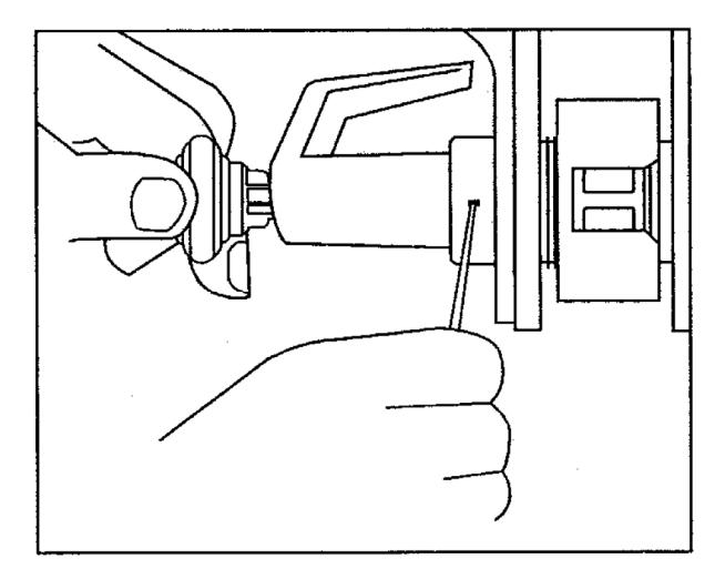
FIG. 8: REVERSE LEVER HANDING
With the Secondary Lever and Secondary side housing off:
1. Insert key into Primary side cylinder, turn key 45° (either di-
- rection) and depress Lever Catch. Pull Lever off.
- 2. Use the Primary side Spindle to rotate the Lock Body Housing 180 degrees. Be sure Lever Catch (shown in Fig. 6) faces the door edge. If necessary, depress the Lever Catch to allow the Primary side Spindle to rotate 180 degrees.
- 3. With key in cylinder untouched (still at 45°), position the Lever on the Spindle and press until Lever Catch engages. Remove key and test Lever for proper engagement by turning and pulling. For interchangeable core (IC) models, see pages 5 and 6.
LOCK INSTALLATION
Important : Before proceeding, be sure to physically block the door to prevent its closing during this installation procedure.
INSTALL PRIMARY SIDE AND LOCK BODY HOUSING
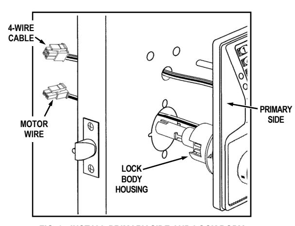
FIG. 9: INSTALL PRIMARY SIDE AND LOCK BODY (Lever, Housing & Lock Body)
- 1. As shown in Fig. 9, insert Motor Wire plug through the 2- 1/8" hole and insert the 4-Wire Cable through the 1" hole.
- 2. Insert Primary side (with the Lock Body Housing) into door and be sure to properly engage the Lock Body Housing with the Latch as shown in Fig. 10.
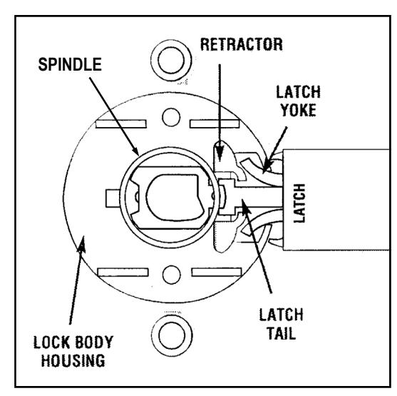
FIG. 10: VIEW FROM SECONDARY SIDE OF DOOR
The Latch Yoke must engage the Lock Body Housing and the Tailpiece must engage the Retractor.
INSTALL SECONDARY SIDE
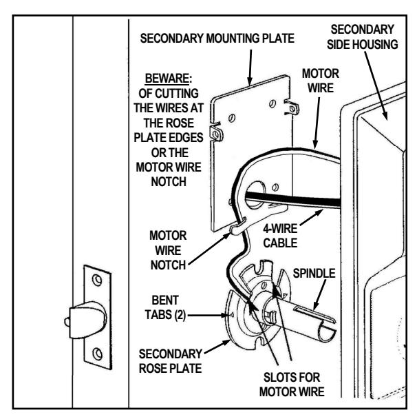
FIG. 11: INSTALL SECONDARY SIDE
1. Place the Secondary Rose Plate over Spindle and on door. Align the two slots with the two 3/8" holes in door (the Rose Plate is marked with " TOP ", circled in Fig. 12) and the bent tabs facing door (the bent tabs bite into wooden doors, preventing their rotation; for metal doors, drill small holes to allow the Secondary Rose Plate to sit flush against door). Fasten with two 8-32 x 1-1/4 Phillips pan head screws through the Secondary Rose Plate, engaging and securing the Lock Body Housing. Do not over-tighten.
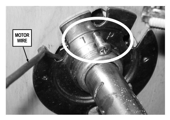
FIG. 12: SECONDARY ROSE PLATE INSTALLATION
2. Position the Secondary Mounting Plate and pull the 4-Wire Cable through the Mounting Plate opening (be sure not to pinch or cut wires). Fasten the Secondary Mounting Plate with two 8-32 flat head screws and two sheet metal screws (do not over-tighten). Note: Be sure the Secondary Mounting Plate is perfectly vertical before installing the sheet metal screws (see Fig. 13 for screw locations). Note: As you tighten the screws, the Secondary Mounting Plate pulls in and secures the Primary side housing to the door.
IMPORTANT: See Fig. 11 and 13: The Motor Wire must come through either slot in the Secondary Rose Plate and be secured by the Motor Wire Notch without pinching or cutting the wires.
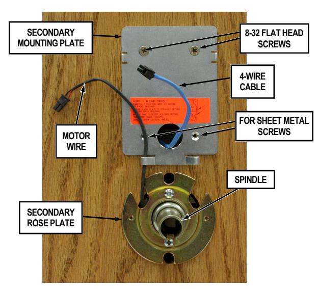
FIG. 13: SECONDARY SIDE
-
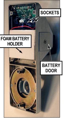
3. Install Battery Pack inside Secondary housing. The Battery Door is installed at the factory. Proceed as follows:
- a. Remove Battery Door by turning the Battery Door Screw two (2) turns counter clockwise. Warning: Do not turn this screw more than two (2) turns because more turns may cause the screw to detach from the Battery Door.
- b. Connect the Battery Pack Plug to its corresponding Power Plug located inside the Foam Battery Holder.
- c. Slide Battery Pack into the Foam Battery Holder.
- d. Replace Battery Door and tighten Battery Door Screw.
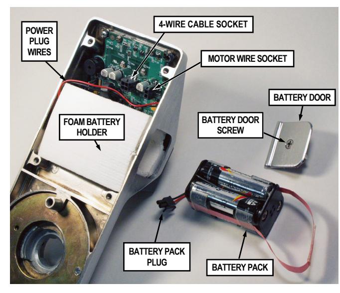
FIG. 14: INSTALL BATTERY PACK
4. Connect the Motor Wire plug into the Motor Wire Socket (see Fig. 15 for location). Connect the 4-Wire Cable into the 4-Wire Cable Socket. Note: These plugs and sockets fit only one way--do not force them. Seal the plugs and sockets with dielectric grease (included). Upon connection of the 4-Wire Cable, listen for three beeps.
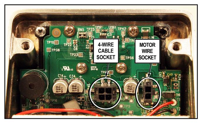
FIG. 15: 4-WIRE CABLE & MOTOR WIRE SOCKETS
- 5. Place Secondary side housing over the Spindle, making sure that all wires are through the housing before tightening the two bolts. Do not allow the wires to cross or lay on top of each other. Jiggle the wires to be sure the wire opening does not pinch or cut wires before fastening bolts.
- 6. Secure the Secondary side housing to the Primary side housing with the two 10-32 x 2 1/4" screws as shown in Fig. 16.
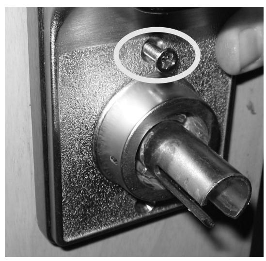
FIG. 16: SECURE THE SECONDARY TO THE PRIMARY HOUSING
7. Secure the top of the Secondary housing to the Secondary mounting plate by inserting the two trim 4-40 flathead Phillips head screws. See Fig. 17.
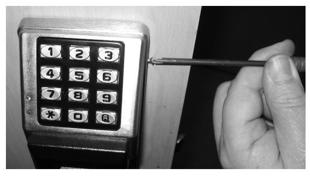
FIG. 17: SECURE THE TOP OF THE SECONDARY HOUSING
8. ATTACHING LEVERS AND LOCKSETS
Interchangeable Core (IC) Models:
Skip to the section, "INTERCHANGEABLE (IC) LOCKS" below.
Standard Levers and Cylinders:
Standard levers and standard lock cylinders are both included in non-IC lock models.
a. Install the tailpiece, cylinder retainer and cylinder into the standard lever as shown in Fig. 18.
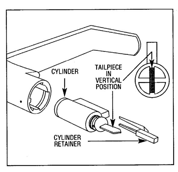
FIG. 18: STANDARD CYLINDER-LEVER, TAILPIECE AND RE-TAINER.
- b. Attach the Primary side Lever by first inserting the metal key into the Primary side lock cylinder and turning the key 45° in either direction.
- c. Insert the Lever on the Spindle and push the Lever in until it engages with the Lever Catch (it may be necessary to turn the key back and forth while installing the Lever).
- d. Install the Secondary side Lever in the same manner as the Primary.
- e. Test both Levers to be sure they are on securely and operate without binding. Be sure the Primary side key retracts the latch when the key is turned in either direction. BE SURE TO TEST THE LEVERS AND CYLIN-DERS FOR PROPER OPERATION BEFORE CLOS-ING DOOR.
INTERCHANGEABLE (IC) LOCKS
Interchangeable (IC) cores require special levers. If necessary, remove both the Primary and Secondary standard Levers (with their standard cylinders) before proceeding. (To remove standard Primary or Secondary side Levers, insert key into cylinder, turn key 45° in either direction, depress the Lever Catch and pull off the Lever).
Interchangeable (IC) cores and their specialized levers are both available from your Alarm Lock dealer.
INSTALL INTERCHANGEABLE (IC) CORES
- 1. Insert Primary side IC Lever on Spindle and push in until it engages with the Lever Catch.
- 2. Insert control key in the Primary side core and turn clockwise.
- 3. Insert IC core Tailpiece (shown in Fig. 19 and Fig. 20) into Primary side core. Note: Tailpieces are used in Primary side cores only . Use ONLY an Alarm Lock IC core Tailpiece.
- 4. With control key in Primary side core, insert core fully into Lever.
- 5. Turn key counterclockwise and remove control key.
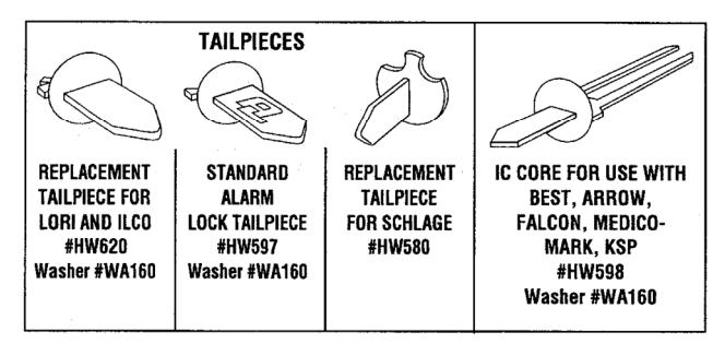
FIG. 19: STANDARD AND IC CORE TAILPIECE VARIETIES
- 6. Insert Secondary side IC Lever on Spindle and push in until it engages with the Lever Catch.
- 7 . Insert control key in Secondary side core and turn clockwise. Do NOT insert Tailpiece into Secondary side core.
- 8. With control key in Secondary side core, insert core fully into lock.
- 9. Turn key counterclockwise and remove key.
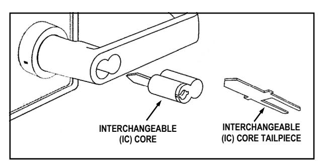
FIG. 20: INSTALL INTERCHANGEABLE (IC) CORE
CHANGING AN EXISTING IC CORE
- 1. Remove the existing Primary side IC core by inserting its control key, then turning the key clockwise and pulling the key to remove the core. Set core aside.
- 2. Insert Alarm Lock Tailpiece with washer into new core.
- 3. Insert new control key into new core, turn clockwise.
- 4. Insert new core into lever and turn key counterclockwise to lock in position.
- 5. Remove new control key.
- 6. Remove the existing Secondary side IC core by inserting its control key, then turning the key clockwise and pulling the key to remove the core. Set core aside.
- 7. Do NOT insert a tailpiece. Insert new control key into new core, turn clockwise.
- 8. Insert new core into lever and turn key counterclockwise to
- lock in position.
- 9. Remove new control key.
REMOVING THE IC CORE & LEVER
- 1. Remove the existing Primary or Secondary IC core by inserting the control key, then turning the key clockwise and pulling the key to remove the core.
- 2. Use a screwdriver to push inside of Lever Catch to the side (see Fig. 21). Pull off the IC lever.
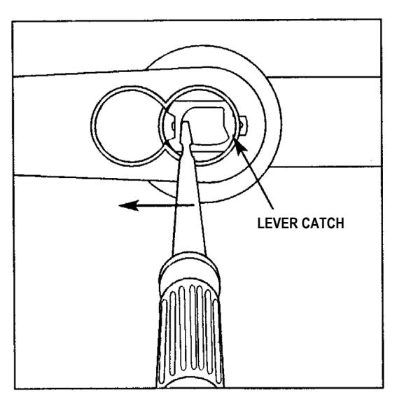
FIG. 21: REMOVING THE IC CORE LEVER
PROGRAMMING
Your lock can be programmed (and re-programmed again and again) to suit your changing requirements. Instead of distributing metal keys, distribute User Codes -- and delete them from the lock firmware when needed. To program your PDL6300 lock, see WI2265.
TROUBLESHOOTING
Electronic Trouble:
Locks works in reverse.
Reverse motor wires in connector.
Lock will not accept new User Codes during programming.
Disconnect battery connector, hold down any keypad button until lock resets, then reconnect and start programming again.
Lock drains batteries quickly.
Check all wires for pinching or cutting. Check for water damage. If condition persists, call Technical Service.
Lock is inoperative.
Check batteries for proper polarity and check for cut wires.
Lock produces high pitch steady tone during lock operation.
Low battery signal - replace batteries.
Mechanical Trouble:
Lever pulls off.
Lever Catch is not fully engaged. Lock is not centered on door. Door is too thick. (See Fig. 7).
Unable to assemble Primary side Lever.
Key and Tailpiece orientation are incorrect (See Figs. 18 - 20).
Latch will not fully retract.
Lock is not properly engaged with latch or misaligned. Lock is not centered on the door (See Fig. 10).
Key binds in lock.
Lever Catch not fully engaged. Lock is not centered on door. Check for proper Tailpiece and proper orientation of Tailpiece (See Figs. 18 - 20).
SOCKET CONNECTIONS
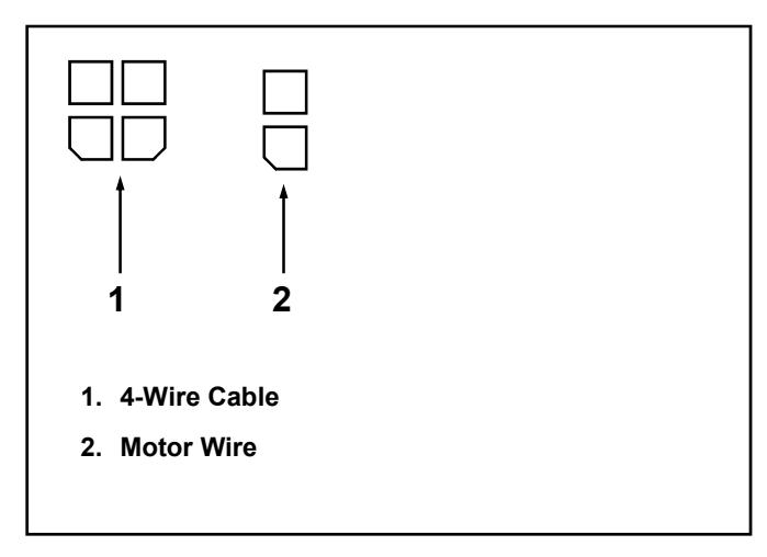
FIG. 22: SOCKET CONNECTIONS
ALARM LOCK LIMITED WARRANTY
ALARM LOCK SYSTEMS, INC. (ALARM LOCK) warrants its products to be free from manufacturing defects in materials and workmanship for twenty four months following the date of manufacture. ALARM LOCK will, within said period, at its option, repair or replace any product failing to operate correctly without charge to the original purchaser or user.
This warranty shall not apply to any equipment, or any part thereof, which has been repaired by others, improperly installed, improperly used, abused, altered, damaged, subjected to acts of God, or on which any serial numbers have been altered, defaced or removed. Seller will not be responsible for any dismantling or reinstallation charges, environmental wear and tear, normal maintenance expenses, or shipping and freight expenses required to return products to ALARM LOCK. Additionally, this warranty shall not cover scratches, abrasions or deterioration due to the use of paints, solvents or other chemicals.
THERE ARE NO WARRANTIES, EXPRESS OR IM-PLIED, WHICH EXTEND BEYOND THE DESCRIPTION ON THE FACE HEREOF. THERE IS NO EXPRESS OR IMPLIED WARRANTY OF MERCHANTABILITY OR A WARRANTY OF FITNESS FOR A PARTICULAR PUR-POSE. ADDITIONALLY, THIS WARRANTY IS IN LIEU OF ALL OTHER OBLIGATIONS OR LIABILITIES ON THE PART OF ALARM LOCK.
Any action for breach of warranty, including but not limited to any implied warranty of merchantability, must be brought within the six months following the end of the warranty period.
IN NO CASE SHALL ALARM LOCK BE LIABLE TO ANY-ONE FOR ANY CONSEQUENTIAL OR INCIDENTAL DAMAGES FOR BREACH OF THIS OR ANY OTHER WARRANTY, EXPRESS OR IMPLIED, EVEN IF THE LOSS OR DAMAGE IS CAUSED BY THE SELLER'S OWN NEGLIGENCE OR FAULT.
In case of defect, contact the security professional who installed and maintains your security system. In order to exercise the warranty, the product must be returned by the security professional, shipping costs prepaid and insured to ALARM LOCK. After repair or replacement, ALARM LOCK assumes the cost of returning products under warranty. ALARM LOCK shall have no obligation under this warranty, or otherwise, if the product has been repaired by others, improperly installed, improperly used, abused, altered, damaged, subjected to accident, nuisance, flood, fire or acts of God, or on which any serial numbers have been altered, defaced or removed. ALARM LOCK will not be responsible for any dismantling, reassembly or reinstallation charges, environmental wear and tear, normal maintenance expenses, or shipping and freight expenses required to return products to ALARM LOCK. Additionally, this warranty shall not cover scratches, abrasions or deterioration due to the use of paints, solvents or other chemicals.
This warranty contains the entire warranty. It is the sole warranty and any prior agreements or representations, whether oral or written, are either merged herein or are expressly cancelled. ALARM LOCK neither assumes, nor authorizes any other person purporting to act on its behalf to modify, to change, or to assume for it, any other warranty or liability concerning its products.
In no event shall ALARM LOCK be liable for an amount in excess of ALARM LOCK's original selling price of the product, for any loss or damage, whether direct, indirect, incidental, consequential, or otherwise arising out of any failure of the product. Seller's warranty, as hereinabove set forth, shall not be enlarged, diminished or affected by and no obligation or liability shall arise or grow out of Seller's rendering of technical advice or service in connection with Buyer's order of the goods furnished hereunder.
ALARM LOCK RECOMMENDS THAT THE ENTIRE SYS-TEM BE COMPLETELY TESTED WEEKLY.
Warning: Despite frequent testing, and due to, but not limited to, any or all of the following; criminal tampering, electrical or communications disruption, it is possible for the system to fail to perform as expected. ALARM LOCK does not represent that the product/system may not be compromised or circumvented; or that the product or system will prevent any personal injury or property loss by burglary, robbery, fire or otherwise; nor that the product or system will in all cases provide adequate warning or protection. A properly installed and maintained alarm may only reduce risk of burglary, robbery, fire or otherwise but it is not insurance or a guarantee that these events will not occur. CONSEQUENTLY, SELLER SHALL HAVE NO LIA-BILITY FOR ANY PERSONAL INJURY, PROPERTY DAMAGE, OR OTHER LOSS BASED ON A CLAIM THE PRODUCT FAILED TO GIVE WARNING. Therefore, the installer should in turn advise the consumer to take any and all precautions for his or her safety including, but not limited to, fleeing the premises and calling police or fire department, in order to mitigate the possibilities of harm and/or damage.
ALARM LOCK is not an insurer of either the property or safety of the user's family or employees, and limits its liability for any loss or damage including incidental or consequential damages to ALARM LOCK's original selling price of the product regardless of the cause of such loss or damage.
Some states do not allow limitations on how long an implied warranty lasts or do not allow the exclusion or limitation of incidental or consequential damages, or differentiate in their treatment of limitations of liability for ordinary or gross negligence, so the above limitations or exclusions may not apply to you. This Warranty gives you specific legal rights and you may also have other rights which vary from state to state.