Alarm_Lock_DL3500EX_Installation_Instructions
Open the original PDF document
View PDF

Alarm Lock Systems, Inc. A division of the NAPCO Security Group 345 Bayview Avenue Amityville, NY 11701 Tel: (631) 789-4871 Fax: (631) 789-3383 www.alarmlock.com
Napco Group Europe, Ltd. 224 Europa Blvd. Gemini Business Park Warrington, WA5 5TN United Kingdom Tel: 44-(0)-1925-242-428 Fax: 44-(0)-1925-242-429 www.napcoeurope.com
PREPARING DOOR FOR INSTALLATION
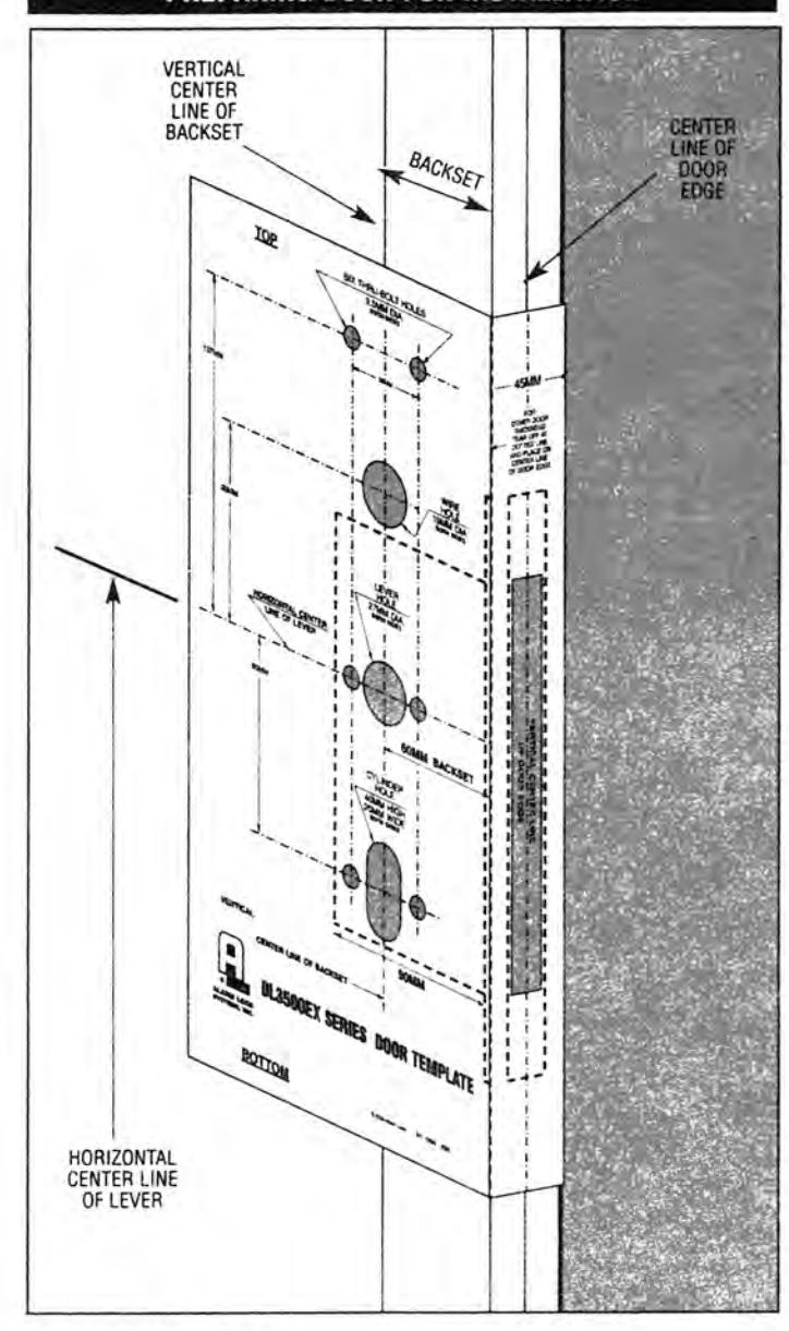
DOOR PREPARATION:
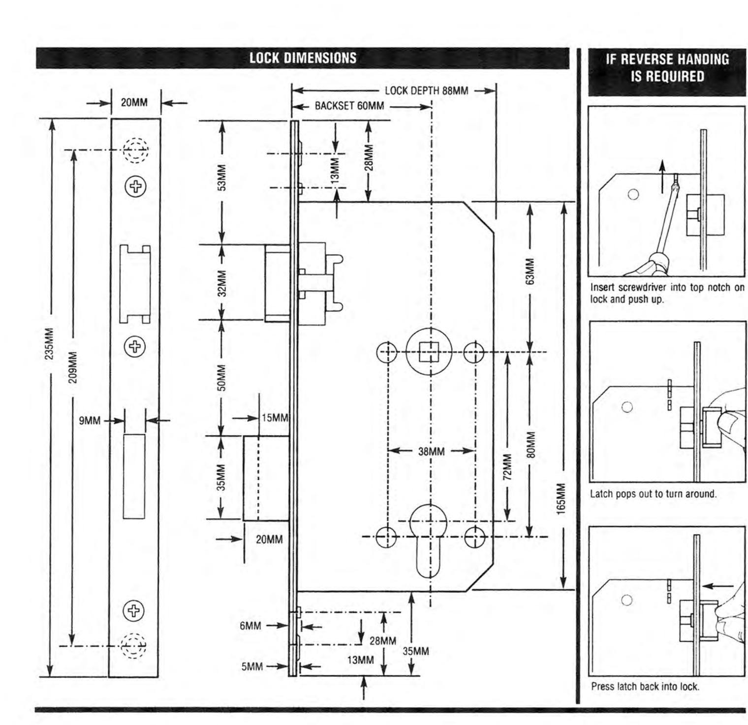
- A. Mark Horizontal Center Line of Lever (at recommended height) on both sides of door, Mark Vertical Center Line of Door edge, Mark Vertical Center Line of Backset (minimum 60MM) on both sides of door.
- B. Tape template in position on door, line up horizontal and vertical lines.
- C. Mark all hole centers on each side of door as per template.
- D. Mortise for lock and lock front in center of door edge as per template.
- E. Drill all holes as per template. It is recommended that all Thru holes be drilled from each side to avoid splintering.
METAL DOORS require horizontal and vertical lock case support. "Provided by door manufacturer".
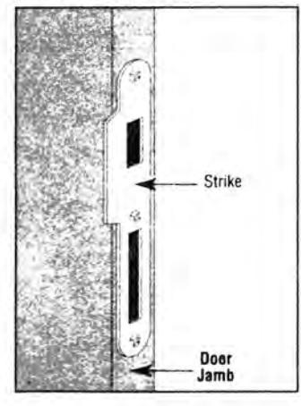
STRIKE INSTALLATION: . Position strike on door jamb and trace.
3. Mortise deep enough to allow latchbolt and deadbolt to fully extend.
INSTALLATION
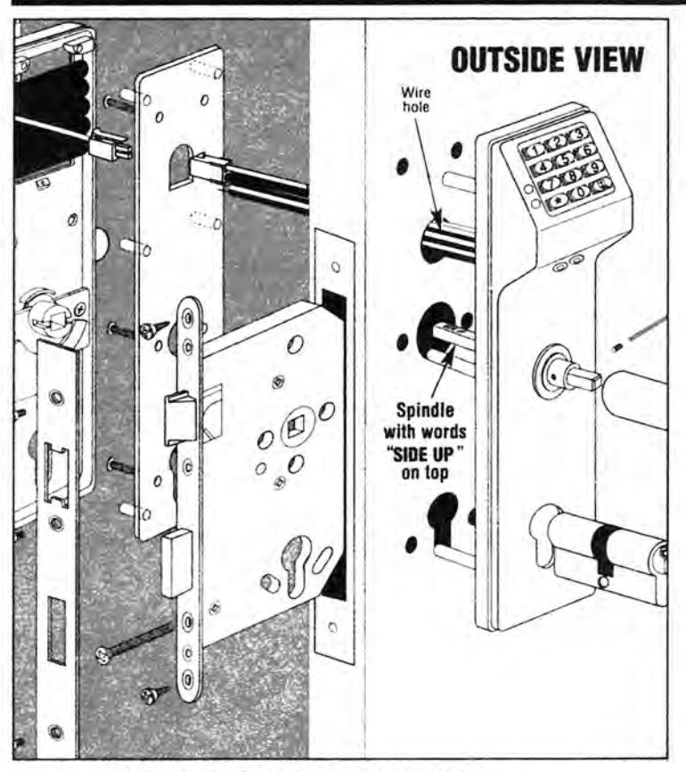
INSTALLING LOCK AND OUTSIDE TRIM ASSEMBLY A. Insert lock into cavity and fasten with 2 screws. B. Push all wires through Wire Hole in door. Position and Push Outside Housing Assembly through door and lock.
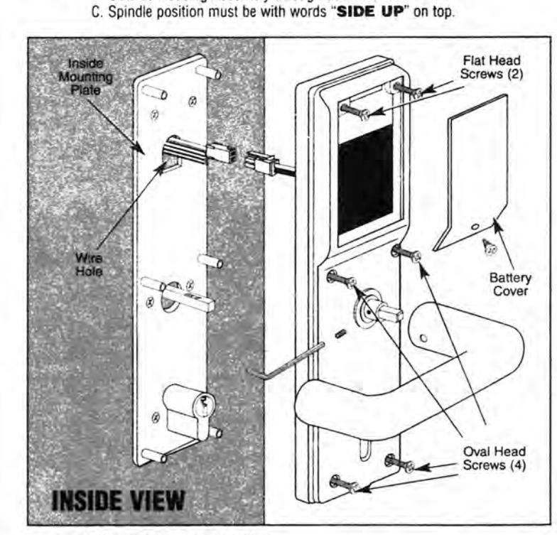
INSTALLING INSIDE ASSEMBLY
-
A. Pull all wires through wire hole in Inside Mounting Plate. B. Position and fasten Inside Mounting Plate with 6 screws. Do not pinch or cut wires.
- C. Position Inside Housing Assembly on door and fasten with 6 screws. D. Align and plug together Battery Connector. Seal with Dielectric Grease included. Fold wires and slide battery case into Inside Housing assembly.
- E. Position and fasten Battery Cover with 1 screw.
BEFORE CLOSING DOOR TEST LOCK FOR PROPER OPERATION
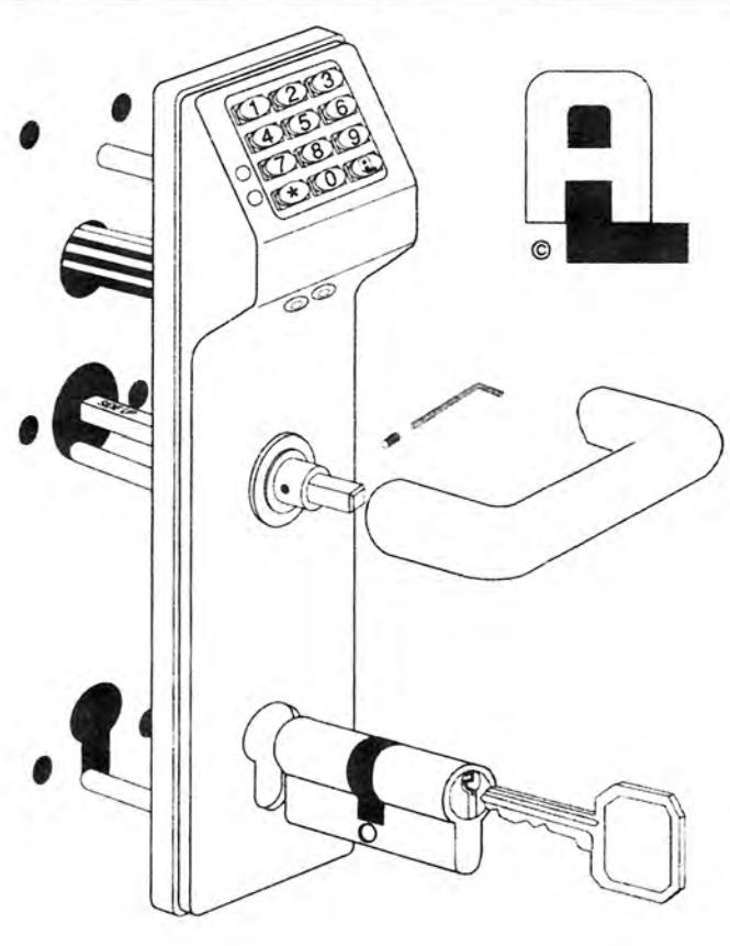
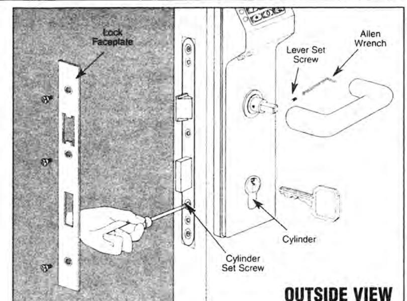
INSTALLING CYLINDER AND LEVERS
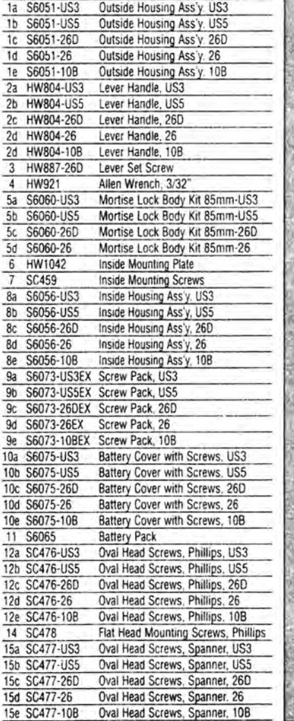
Description
Key Part No.
- A. Insert Cylinder through Outside Assembly and Tighten the Cylinder Set Screw.
- B. Position and fasten lock faceplate with 3 screws.
- C. Place levers on spindle and fasten with the Lever Set Screw, both sides.
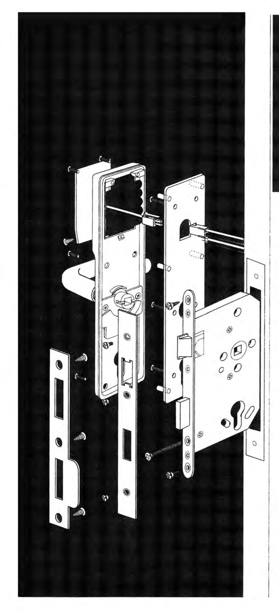
REFERENCE: EXPLODED VIEW AND PARTS LIST