Alarm Lock RR-RECEIVER Wireless General Purpose Remote Control Receiver Installation and Programming Instructions
Open the original PDF document
View PDF
Amityville, New York 11701 For Sales and Repairs 1-800-ALA-LOCK For Technical Service 1-800-645-9440 or visit us at http://tech.napcosecurity.com/ (Note: Technical Service is for security professionals only) Publicly traded on NASDAQ Symbol: NSSC
RR-RECEIVER
Wireless General Purpose Remote Control Receiver INSTALLATION AND PROGRAMMING INSTRUCTIONS
© ALARM LOCK 2016 WI2012A 02/16
OVERVIEW
The RR-RECEIVER is a wireless general-purpose remote control receiver that provides remote unlocking to an Alarm Lock locking device, or for any other application requiring a radio-controlled solid state relay closure .
The RR-RECEIVER is factory supplied with Alarm Lock compatible battery connector plugs, simplifying installation within Alarm Lock cylindrical locking devices for wireless "remote release". The RR-RECEIVER can be used with a standard Alarm Lock battery pack or by simply cutting the power battery connector and using your own power supply (see SPECIFICA-TIONS for current consumption and power requirements). RR-RECEIVER features include:
- Can be installed inside the lock housing to provide a "remote release" (remote unlock) function with legacy Alarm Lock locking devices (models DL2700, DL2800 or T3 non-Networx models without an integral radio
- Built-in battery connectors for quick installation inside Alarm Lock T2 or T3 locking devices
- Programmable " Relay Closure Duration ", " Relay 'Hold Off' Time " and " Relay Toggle Mode " for advanced applications
Up to fifty (50) individual remote buttons can be "paired" (connected) to one RR-RECEIVER
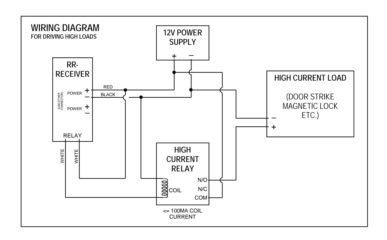
Can be used to drive high loads such as door strikes or magnetic locks by wiring to an auxiliary high current relay (see Specifications and Wiring Diagram for more information)
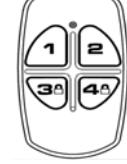
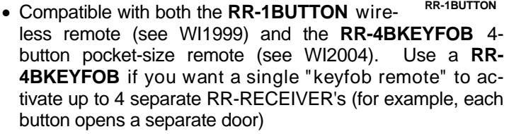
RR-4BKEYFOB
Years of operation with a standard Alarm Lock battery pack (see Specifications below for current consumption and power requirements)
Relay programming and remote button pairings are maintained even when power is removed
For mortise locks, use the RR-MORTISE kit
Note: In this manual, "remote button" is used to describe the single button on the RR-1BUTTON (see WI1999) or any one of the four buttons on the RR-4BKEYFOB (see WI2004).
SPECIFICATIONS
Power Requirements : ......... 5-12VDC or use AL battery pack Solid State Relay Contact Current : ............. 30mA maximum Current Consumption : ..... 50 microamperes (µA) idle current
OPERATION
When a paired remote button is pressed, its paired RR-RECEIVER relay will typically close within 2 seconds of the but-
ton press, and will remain closed for its programmed " Relay Closure Duration " (2 seconds by default, programmable from 1-250 seconds).
After the " Relay Closure Duration " ends and the relay opens, an optional Relay "Hold Off" Time can be added during which time the RR-RECEIVER will ignore all paired remote button presses ( Relay "Hold Off" Time is 0 seconds by default, programmable from 0-250 seconds). After the Relay "Hold Off" Time ends, the RR-RECEIVER is then ready to respond to the next wireless remote button press. This Relay "Hold Off" Time might be used for mechanical locking devices that require a minimum time to complete their operation, such as an entry gate swinging mechanism or mortise locks that require extra time to complete their mechanical operations (we recommend a minimum of 3 seconds "Hold Off" time be programmed when the RR-RECEIVER is used with Alarm Lock Exit Trim and Mortise locking devices). The columns in the table below (from left to right) summarize these RR-RECEIVER operations:
|
SUMMARY OF RR-RECEIVER RELAY
OPERATIONS OVER TIME |
|||
|---|---|---|---|
|
Remote
Button Press |
RR-RECEIVER
"Relay Closure Duration" |
RR-RECEIVER "Relay
'Hold Off' Time |
RR-RECEIVER "Relay
'Hold Off' Time Ends |
|
0.5-2 sec.
delay before relay closes |
Default is 2
seconds; programmable between 1-250 seconds |
Relay opens and ignores
all paired remote button presses. Default time is zero seconds; programmable between 0-250 seconds |
The RR-RECEIVER is
ready to respond to the next wireless remote button press |
A separate programmable relay option is " Relay Toggle Mode " where each press of a paired remote button causes the relay to alternate back and forth between open and closed states like a toggle switch. See " RELAY TOGGLE MODE " for details. Note: If " Relay Toggle Mode " is programmed, we recommend powering the RR-RECEIVER with a DC power supply, as the voltage drain due to extended relay close durations will decrease battery life. See SPECIFICATIONS .
CAPACITY
Up to fifty (50) individual remote buttons can be "paired" to one RR-RECEIVER. However, a remote button can only be paired with one RR-RECEIVER at a time. If a paired remote button is later paired with a second RR-RECEIVER, the first pairing will be erased.
GETTING STARTED
First power the RR-RECEIVER, then perform the "Pairing Procedure" and "Relay Operational Programming".
For installations inside Alarm Lock housings: Jump to the section " INSTALLATION INSIDE AN ALARM LOCK DEVICE HOUSING ". You can perform the "Pairing Procedure" and "Relay Operational Programming" with the RR-
RECEIVER inside or outside the housing.
For other "general purpose" applications: First power the RR-RECEIVER either by plugging a standard Alarm Lock battery pack's male plug into the RR-RECEIVER female power socket, or by cutting the RR-RECEIVER power plugs and wiring a 9V battery or your own compatible DC power supply (see SPECIFICATIONS ).
Note: The use of a pencil or other small tool is required to press the recessed button on the RR-RECEIVER.
HOW TO PAIR A REMOTE TO A RECEIVER
After the RR-RECEIVER is powered, be sure to have either an RR-1BUTTON or RR-4BKEYFOB wireless remote powered and ready. Pair a remote button to a RR-RECEIVER as follows:
- a. Press and release the RR-RECEIVER button . The green LED on the RR-RECEIVER will turn on, indicating the RR-RECEIVER is ready to pair ("pairing mode" begins). Within 30 seconds perform the next step.
- ( Note: Cancel pairing mode by simply pressing and releasing the RR-RECEIVER button again; the RR-RECEIVER LED will flicker and turn off).
-
b. With the RR-1BUTTON or RR-4BKEYFOB wireless remote in hand
, observe the remote's LED as you perform the following:
- On the remote, press and hold a button...
-
Continue holding button on remote until LED
flashes green
,
then release the button
. Observe the remote LED:
-
Solid green LED
= Pairing successful; go to step
c
to test.
- Note: The RR-RECEIVER LED will blink twice indicating it is ready for another pairing.
- Solid red LED = Pairing failure (start again at step a ).
-
Solid green LED
= Pairing successful; go to step
c
to test.
-
To pair another remote button to this RR-RECEIVER, repeat step
b
(or do nothing and after 30 seconds the RR-RECEIVER's "pairing mode" will end automatically).
- Pairing mode can be exited by simply pressing and releasing the RR-RECEIVER button again; the RR-RECEIVER LED will flicker and turn off.
- c. Test the pairing: Once paired to a remote button, the RR-RECEIVER automatically enters a "Test Mode" that works in conjunction with the relay to simplify testing. To save battery power, this Test Mode ends after 30 minutes, and is nothing more than an LED on the RR-RECEIVER that turns on when its relay activates.
- Simply press the button on the paired remote and ensure the RR-RECEIVER green LED turns on. Note: This LED will turn on for the length of the programmed Relay Closure Duration (see RELAY OPERATIONAL PROGRAM-MING , below).
If you wish to re-activate "Test Mode" for another 30 minutes : Press and release the RR-RECEIVER button (LED turns on), wait two seconds, then press and release the RR-RECEIVER button again (LED turns off).
Once paired, you can now program the RR-RECEIVER Relay Closure Duration and Relay "Hold Off" Time in one procedure, detailed below. Alternatively, you can also program
" Relay Toggle Mode ". If you choose not to program these relay operations, the default Relay Closure Duration is 2 seconds, the default Relay "Hold Off" Time is zero (0) seconds, and by default "Relay Toggle Mode" is disabled.
RELAY OPERATIONAL PROGRAMMING
RELAY CLOSURE DURATION: When a paired remote button is pressed, its paired RR-RECEIVER relay will typically close within 2 seconds of the button press, and will remain closed for its programmed " Relay Closure Duration " (2 seconds by default, programmable from 1-250 seconds).
RELAY "HOLD OFF" TIME: After the " Relay Closure Duration " ends and the relay opens, an optional Relay "Hold Off" Time can be added during which time the RR-RECEIVER will ignore all paired remote button presses. After the Relay "Hold Off" Time ends, the open RR-RECEIVER relay is then ready to respond to another remote button press (the default Relay "Hold Off" Time is 0 seconds, programmable from 0-250 seconds).
Program the Relay Closure Duration and optional Relay "Hold Off" Time in one set of steps, below. We recommend having these durations planned and ready beforehand to simplify programming. Also, verify the RR-RECEIVER LED is off before continuing:
- a. Press and hold the button on the RR-RECEIVER until the solid green LED on the RR-RECEIVER turns off. The RR-RECEIVER is now in "relay program mode".
- b. Press and release the RR-RECEIVER button for each second you wish to assign to the Relay Closure Duration . (For example, 1 press = 1 second, 2 presses = 2 seconds, etc.).
- c. Stop and observe the RR-RECEIVER: Its LED will verify the Relay Closure Duration entered by flashing once for each second pressed in step b .
- (If no Relay "Hold Off" Time is desired, go to step f )
- d. Press and release the RR-RECEIVER button for each second you wish to assign to the Relay "Hold Off" Time . (For example, 1 press = 1 second, 2 presses = 2 seconds, etc.).
- e. Stop and observe the RR-RECEIVER: Its LED will verify the Relay "Hold Off" Time entered by flashing once for each second pressed in step d .
- f. Wait for RR-RECEIVER LED to flash rapidly indicating the end of "relay program mode".
- g. Test the pairing: After step f ends, the RR-RECEIVER automatically enters a "Test Mode" that works in conjunction with the relay to simplify testing. To save battery power, this Test Mode ends after 30 minutes, and is nothing more than an LED on the RR-RECEIVER that turns on when its relay activates.
Simply press the button on the paired remote and ensure the RR-RECEIVER green LED turns on for the length of the programmed Relay Closure Duration . If a Relay "Hold Off" Time was programmed, the RR-RECEIVER will likewise ignore all paired remote button presses during this time (its LED will remain off when the paired remote button is pressed).
If you wish to re-activate "Test Mode" for another 30 minutes : Press and release the RR-RECEIVER button (LED turns on), wait two seconds, then press and release the RR-RECEIVER button again (LED turns off).
RELAY TOGGLE MODE: The RR-RECEIVER can be programmed to operate in " Relay Toggle Mode " where each press of the same paired remote button causes the relay to alternate back and forth between open and closed states like a toggle switch. Note: The fastest the relay will toggle between open and closed states is 2 seconds.
Enable " Relay Toggle Mode " as follows:
-
a. Press and hold
the RR-RECEIVER button…
- LED lights solid green (keep holding the button)
- LED turns off (keep holding the button)
- LED lights solid green again
- Release the button
- Wait for RR-RECEIVER LED to flash rapidly and turn off. " Relay Toggle Mode " is now operational.
- b. Test the RR-RECEIVER . After " Relay Toggle Mode " is programmed, the RR-RECEIVER automatically enters a "Test Mode" that works with the relay to simplify testing. To save battery power, Test Mode ends after 30 minutes. Test Mode is simply an LED on the RR-RECEIVER that turns on when its relay closes. To test the " Relay Toggle Mode " operation, press the paired remote button and ensure the RR-RECEIVER LED turns on (indicating relay closure). Press the paired remote button again to ensure the LED turns off (relay open).
If you wish to re-activate "Test Mode" for another 30 minutes : Press and release the RR-RECEIVER button (LED turns on), wait two seconds, then press and release the RR-RECEIVER button again (LED turns off).
DEFAULTING THE RR-RECEIVER
To erase all paired remote buttons and all Relay Operational Programming, returning the RR-RECEIVER to its original factory settings (" Relay Closure Duration " of 2 seconds, Relay "Hold Off" Time of zero seconds and " Relay Toggle Mode " disabled), proceed as follows:
- a. Remove power from the RR-RECEIVER . Wait 3 seconds.
- b. Replace power to the RR-RECEIVER.
- c. Within 5 seconds, press and hold the RR-RECEIVER button until the green LED start to flicker (rapid flashing).
The rapid flashing indicates the RR-RECEIVER has been returned to its original factory settings
INSTALLATION INSIDE AN ALARM LOCK DEVICE HOUSING
T3 Alarm Lock locking device models have a programmable Remote Input feature (momentary closure to unlock the locking device, enabled by default). Check the Programming Instructions that came with your Alarm Lock locking device; if in doubt, enter Program Mode and enable Function 65 (press ;6 First insert the right side of the
5: ) to enable this Remote Input feature. For T2 models, the Remote Input feature is enabled by default; see the Programming Instructions that came with your T2 locking device.
To install the RR-RECEIVER inside an Alarm Lock locking device housing, such as a model DL2700 or DL2800, proceed as follows:
- 1. Remove the screw at the back of the lock housing and remove the rear cover.
- 2. Remove and disconnect the battery pack.
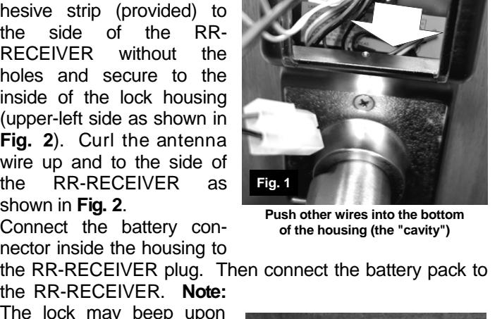
- 3. Inside the rear housing, locate and take hold of the two white "Remote Input" wires and the disconnected battery plug connector. Push all other wires and the motor wire into
the bottom "cavity" of the rear housing ( Fig. 1 ).
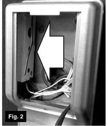
4. Apply the double-sided adhesive strip (provided) to the side of the RR-RECEIVER without the holes and secure to the inside of the lock housing (upper-left side as shown in Fig. 2 ). Curl the antenna wire up and to the side of the RR-RECEIVER as shown in Fig. 2 .
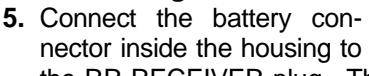
the RR-RECEIVER. Note: The lock may beep upon supplying power; the internal clock may need to be reset (if equipped).
- 6. Connect the remote input wire of the lock to one white wire of the RR-RECEIVER. Then connect the other remote input wire to the other white wire of the RR-RECEIVER.
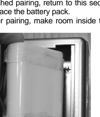
- 7. Before placing the battery pack into the housing, perform the " PAIRING PRO-
CEDURE " that pairs a wireless remote button to the RR-RECEIVER. When
finished pairing, return to this section and perform step 8 to replace the battery pack.
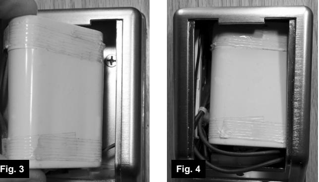
8. After pairing, make room inside the housing for the battery
battery pack into the housing...
Secure the RR RECEIVER to the side as shown
...then slide in the remaining half.
pack: Before replacing the battery pack, carefully push all of the remaining wires that are inside the housing down into the "cavity" shown in Fig. 1 . Replace the battery pack by placing the right side of the battery pack into the housing first (see Fig. 3 and Fig. 4 ).
9. At the back of the lock, replace the cover and secure with the cover screw.
GENERAL PURPOSE APPLICATIONS
When driving high loads such as door strikes or magnetic locks, the RR-RECEIVER solid state relay should be wired to drive an auxiliary high current relay as shown in the following wiring diagram:
ALARM LOCK LIMITED WARRANTY
ALARM LOCK SYSTEMS, INC. (ALARM LOCK) warrants its products to be free from manufacturing defects in materials and workmanship for 24 months following the date of manufacture. ALARM LOCK will, within said period, at its option, repair or replace any product failing to operate correctly without charge to the original purchaser or user.
This warranty shall not apply to any equipment, or any part thereof, which has been repaired by others, improperly installed, improperly used, abused, altered, damaged, subjected to acts of God, or on which any serial numbers have been altered, defaced or removed. Seller will not be responsible for any dismantling or reinstallation charges.
THERE ARE NO WARRANTIES, EXPRESS OR IMPLIED, WHICH EXTEND BEYOND THE DESCRIPTION ON THE FACE HEREOF. THERE IS NO EXPRESS OR IMPLIED WARRANTY OF MERCHANTABILITY OR A WARRANTY OF FITNESS FOR A PARTICULAR PURPOSE. ADDITIONALLY, THIS WARRANTY IS IN LIEU OF ALL OTHER OBLIGATIONS OR LIABILITIES ON THE PART OF ALARM LOCK.
Any action for breach of warranty, including but not limited to any implied warranty of merchantability, must be brought within the six months following the end of the warranty period. IN NO CASE SHALL ALARM LOCK BE LIABLE TO ANYONE FOR ANY CONSEQUENTIAL OR INCIDENTAL DAMAGES FOR BREACH OF THIS OR ANY OTHER WARRANTY, EXPRESS OR IMPLIED, EVEN IF THE LOSS OR DAMAGE IS CAUSED BY THE SELLER'S OWN NEGLIGENCE OR FAULT.
In case of defect, contact the security professional who installed and maintains your security system. In order to exercise the warranty, the product must be returned by the security professional, shipping costs prepaid and insured to ALARM LOCK. After repair or replacement, ALARM LOCK assumes the cost of returning products under warranty. ALARM LOCK shall have no obligation under this warranty, or otherwise, if the product has been repaired by others, improperly installed, improperly used, abused, altered, damaged, subjected to accident, nuisance, flood, fire or acts of God, or on which any serial numbers have been altered, defaced or removed. ALARM LOCK will not be responsible for any dismantling, reassembly or reinstallation charges.
This warranty contains the entire warranty. It is the sole warranty and any prior agreements or representations, whether oral or written, are either merged herein or are expressly canceled. ALARM LOCK neither assumes, nor authorizes any other person purporting to act on its behalf to modify, to change, or to assume for it, any other
4
warranty or liability concerning its products.
In no event shall ALARM LOCK be liable for an amount in excess of ALARM LOCK's original selling price of the product, for any loss or damage, whether direct, indirect, incidental, consequential, or otherwise arising out of any failure of the product. Seller's warranty, as hereinabove set forth, shall not be enlarged, diminished or affected by and no obligation or liability shall arise or grow out of Seller's rendering of technical advice or service in connection with Buyer's order of the goods furnished hereunder.
ALARM LOCK RECOMMENDS THAT THE ENTIRE SYSTEM BE COMPLETELY TESTED WEEKLY.
Warning: Despite frequent testing, and due to, but not limited to, any or all of the following; criminal tampering, electrical or communications disruption, it is possible for the system to fail to perform as expected. ALARM LOCK does not represent that the product/system may not be compromised or circumvented; or that the product or system will prevent any personal injury or property loss by burglary, robbery, fire or otherwise; nor that the product or system will in all cases provide adequate warning or protection. A properly installed and maintained alarm may only reduce risk of burglary, robbery, fire or otherwise but it is not insurance or a guarantee that these events will not occur. CONSEQUENTLY, SELLER SHALL HAVE NO LIABILITY FOR ANY PERSONAL INJURY, PROPERTY DAMAGE, OR OTHER LOSS BASED ON A CLAIM THE PRODUCT FAILED TO GIVE WARNING. Therefore, the installer should in turn advise the consumer to take any and all precautions for his or her safety including, but not limited to, fleeing the premises and calling police or fire department, in order to mitigate the possibilities of harm and/or damage.
ALARM LOCK is not an insurer of either the property or safety of the user's family or employees, and limits its liability for any loss or damage including incidental or consequential damages to ALARM LOCK's original selling price of the product regardless of the cause of such loss or damage.
Some states do not allow limitations on how long an implied warranty lasts or do not allow the exclusion or limitation of incidental or consequential damages, or differentiate in their treatment of limitations of liability for ordinary or gross negligence, so the above limitations or exclusions may not apply to you. This Warranty gives you specific legal rights and you may also have other rights which vary from state to state.