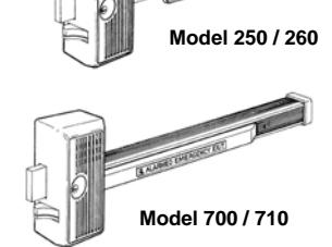
Alarm Lock Panic Exit Device 700, 710, 250, 260 Installation Instructions
Open the original PDF document
View PDF

ELECTRONIC PANIC LOCKS INSTALLATION AND OPERATION INSTRUCTIONS PADDLE ARM MODELS 250 / 260
PUSH BAR MODELS 700 / 710 WATERPROOF MODELS 250WP / 700WP / 710WP
WI1601 04/16
345 Bayview Avenue Amityville, New York 11701 For Sales and Repairs 1-800-ALA-LOCK For Technical Service 1-800-645-9440 or visit us at http://tech.napcosecurity.com/ (Note: Technical Service is for security professionals only) Publicly traded on NASDAQ Symbol: NSSC
© ALARM LOCK 2016
GENERAL DESCRIPTION
Models 250, 260, 700 and 710 are non-handed electronic exit door locking systems. The specific models are:
▪ 250 ········· Clapper Plate Model
▪ 250WP ··· Clapper Plate Waterproof
▪ 260 ········· Clapper Plate Retriggerable
▪ 700 ········· Channel Push Bar
▪ 700WP ··· Channel Push Bar Waterproof
▪ 710 ········· Channel Push Bar Retriggerable
▪ 710WP ··· Channel Push Bar
Retriggerable Waterproof
Arming is accomplished by actuating the deadbolt using a rim cylinder (not included). When armed, depressing the paddle or push bar will release the deadbolt and sound an immediate alarm.
Several other options are available. Jumpers inside the unit allow for either a "Continuous Alarm" or a two-minute "Autoalarm Shutdown".
- "Continuous Alarm" mode : When triggered, the alarm remains sounding until deactivated when relocked with the key.
- "Auto-Alarm Shutdown" mode : When triggered, the alarm remains sounding for two minutes, the lock then checks if the door is closed. If the lock detects the door is closed, the sounder will turn off; if the lock detects the door is still open, the sounder remains on for another two minutes and the process repeats by re-checking the door status every two minutes.
After the initial two minute alarm and automatic shutdown, " Retriggerable " models allow the alarm to reactivate if the door is opened again. The lock remains retriggerable until the door is relocked with the key. Note: Whenever an alarm is caused by opening the door, and the door is left open, the two minute alarm shutdown will be inhibited.
SPECIFICATIONS
All specifications are rated at 72°F (22°C).
Power Source : ....................... 9VDC alkaline battery Battery Life :
For non-waterproof models : 4 years standby in armed mode; 600 two-minute alarm sequences. ("Auto-Alarm Shutdown" mode), 20 hours continuous alarm
For waterproof models : 9VDC long-life sealed alkaline battery pack (part # S6173 ). Increased standby times, alarm sequence cycles and continuous alarm duration (compared with non-waterproof models).
Maximum Current:
| Idle with bolt extended: 22µa @ 9VDC input | |
|---|---|
| Idle with bolt retracted: 18µa @ 9VDC input | |
| Alarm: 50mA | |
| Sound Pressure Level: 99dB (c-weighted @ 10ft.) +/- 3dB | |
| Dimensions (WxHxD): Models 700-710: 33 x 8½ x 3¼ in. | |
| Models 250-260: 18 x 8½ x 3¼ in. | |
| Shipping Weight: Models 700-710: 12 lbs. approx. | |
| Models 250-260: 9 lbs. approx. | |
| Temperature Range:20° to +140°F (-29° to 60°C) | |
| Chassis Construction: Die cast zinc and aluminum | |
| Finish: US28 Aluminum or US312 | |
| Duranodic Powder Coat |
FEATURES
- Non-handed
- Deadbolt with hardened steel insert
- Deadlatch for easy access from inside without alarm
- Deadbolt can be operated by outside key (optional)
- For single or double doors
- Loud dual-piezo horn
- Continuous or two-minute alarm shutdown
- Disarming beep sounds when bolt retracted with key
- Low battery beep when battery needs to be replaced
- Retriggerable models: Automatic re-arming after two minute shutdown
TABLE OF CONTENTS
| GENERAL DESCRIPTION 1 | |
| SPECIFICATIONS 1 | |
| FEATURES 1 | |
| OPTIONAL EQUIPMENT 2 | |
| PRECAUTIONS 2 | |
| SINGLE DOOR INSTALLATIONS 3 | |
| DOUBLE DOOR INSTALLATIONS 7 | |
| OPERATING INSTRUCTIONS 11 | |
| OPERATIONAL TESTING 11 | |
| LOW BATTERY DETECTION 11 | |
| DOGGING OPERATION 11 | |
| SCREW CHART 12-13 | |
| DETAIL ASSEMBLY OF 700 & 710 SERIES 14 | |
| DETAIL ASSEMBLY OF 250 & 260 SERIES 15 | |
| LIMITED WARRANTY 16 |
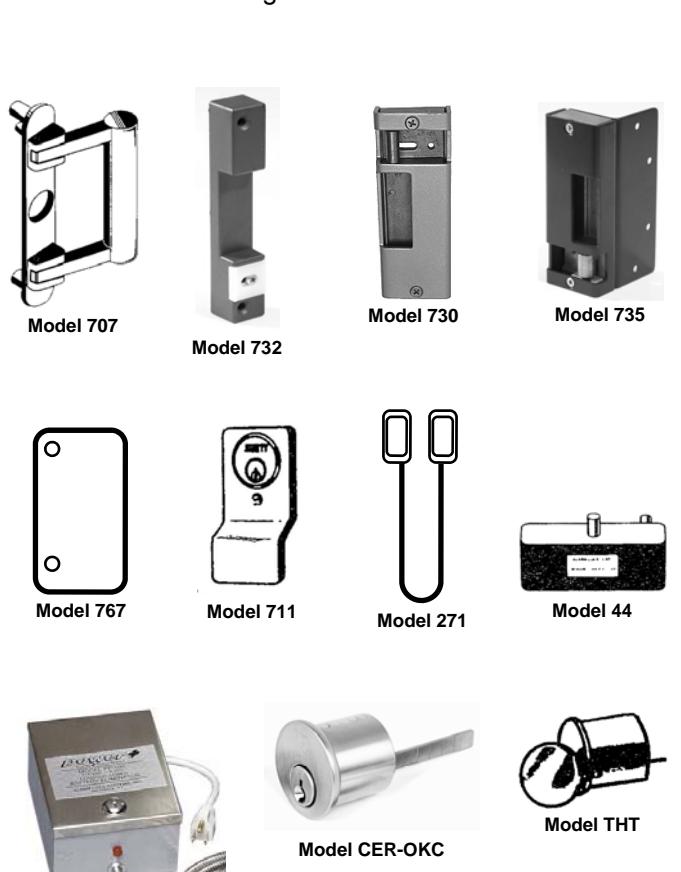
OPTIONAL EQUIPMENT
- Outside Access Door Pull Model 707 For access from building exteriors. Installed on the outside of the door and linked to the lock. After deadbolt is retracted by outside key, a slight pull will release the deadlatch and open door. Cast aluminum, 8" x 1.5".
- Double Door Keeper Model 732 Applied to the surface of the inactive leaf of a pair of doors. Plated case aluminum 7/8" x 6"
- Single Door Keeper Model 730 Supplied for single doors or pairs of doors with mullions.
- Double-Door Strike Model 735 Alarm Lock doubledoor strike Model 735 is specifically designed for the Model 715 Series Delayed Egress Panic Lock
- Finish Back Plate Model 767 Required to conceal the open back of the lock body when mounted on a glass door. Stainless steel 4.5" x 8.5".
- Cylinder Finger Pull Model 711 An inexpensive door pull for use when outside key only access is required.
- Armored Door Loop Model 271 For use with electrified locks. An easy means for bringing electric current from the hinge side of a door frame to the door. 18" flexible armored cable. End brackets are deep drawn anodized aluminum to conceal wire connections.
- Double Door Holder Model 44 The double door holder secures the inactive door to the door frame while the active door is closed. Releasing the active door automatically allows both doors to swing freely. Reversible, right or left hand doors. Cast aluminum 8.5" long, 3" wide and 2.5" High.
- Rim Cylinder Model CER-OKC Used to lock and unlock all of our exit and panic alarm locks from outside. Includes two keys for outside key control (KA or KD).
- Thumb Turn Model THT Used instead of cylinder and keys to retract and project the deadbolt from inside.
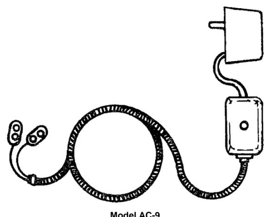
- Battery Eliminator Model AC-9 Provides constant regulated 9VDC power for models 250 and 260. It is simple to install and maintenance free. 117 VAC to 9VDC. The AC-9 conserves the battery and automatically takes over as the power source in the event of a power failure or intentional power cutoff.
- Battery Eliminator Model PP100 Provides unregulated 6-9VDC @ 0-300mA, replacing all power normally supplied by the device's internal batteries, allowing the internal batteries to be used exclusively for battery backup if AC is lost (automatic switchover to battery upon AC input failure). 9 volt adapter harness and 6' (1.8m) armored cable supplied. Input voltage 105- 125VAC @ 60Hz; Input power 10VA max.
PRECAUTIONS
Model PP100
- Do not connect the battery until the installation is complete.
- The Lock Assembly circuit board is fragile. Exercise care while the Lock Cover is removed.
- When making electrical connections to the Lock Assembly, be sure that the wires do not interfere with the mechanical operation of the lock mechanism.
- If the sounder cable is removed from the Lock Assembly circuit board, observe polarity shown on the label when installing.
Single Door Installations
SINGLE DOOR INSTALLATIONS
(For double door installations, turn page 6).
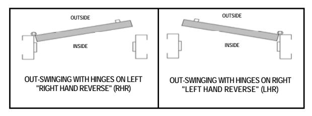
Fig. 1: Cross Section Top View -- Door Hand.
See Fig. 1 to determine the door handing type for your installation. All models are non-handed and can be used for single or double-door installations. For double door installations, skip this section and turn to page 7. The instructions that follow illustrate a typical installation of a model 700/710 to a single "right-hand reverse" door.
1. POSITION THE TEMPLATE
The template positions the lock body relative to the door jamb. Be sure to make an allowance for the gap between the door and the doorjamb ( Note: This gap cannot exceed 5/8" or the latchbolt will not catch within the Keeper Assembly and the door will not lock ).
Close the door and carefully tape the template to the inside surface of the door and the jamb so that the hole for the rim cylinder is about 38" above the floor. (Note special instructions for mounting onto a narrowstile glass door). See Fig. 2.
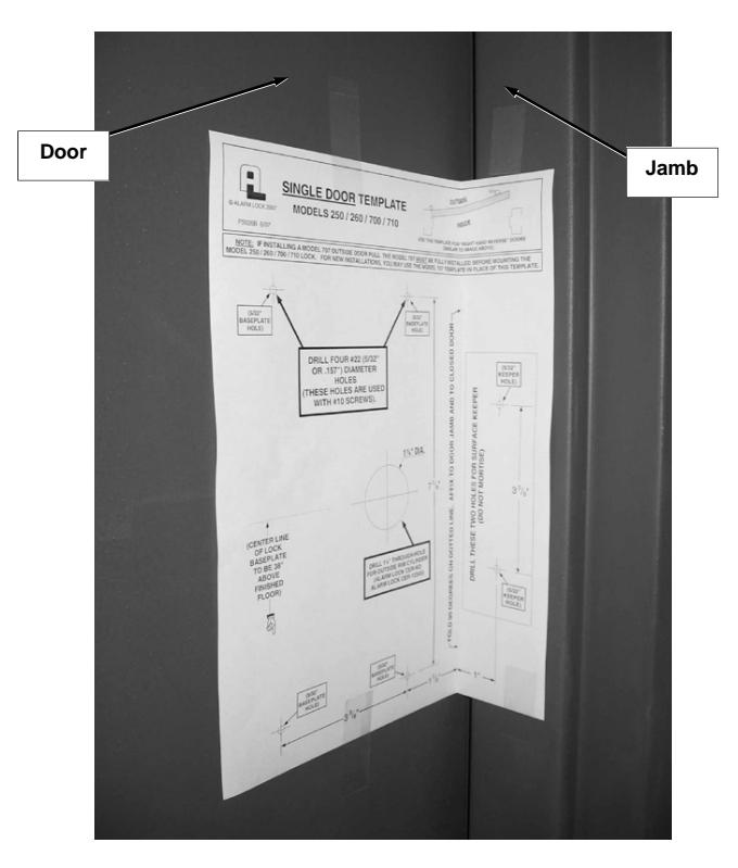
Fig. 2: With door closed, template folded and taped to inside surface of the door and door jamb 38" above floor from mark indicated on template.
2. MARK AND DRILL HOLES
Compare holes referenced on the template (P5026) with holes described in the text below. Reposition the template as often as needed until it is placed correctly. Drill slowly and STRAIGHT through the door.
a. Mark six (6) .157" (5/32") diameter holes, four (4) for the Lock Base Plate and two (2) (of the four shown on the template) for the Keeper Base (P1157).
Note: For mounting onto a narrow-stile glass door, drill only two holes for the Lock Base Plate , along the jamb edge.
- b. IF OUTSIDE CYLINDER (MODEL CER-OKC) IS USED : Mark the center of the 1¼" diameter hole.
- c. IF OUTSIDE PULL (MODEL 707) IS USED : Use the door pull template (WI1627). Mark the center of the four ¼" diameter holes. Then proceed as follows:
For solid wood doors :
- 1. Drill ¼" diameter through-hole.
- 2. From outside of door, use through-hole drilled in previous step to drill a 5/8" diameter hole to a depth of 1¼" only.
For hollow metal doors :
- 1. Drill ¼" diameter through-hole.
- 2. From outside of door, use through-hole drilled in previous step to drill a 5/8" diameter hole in outer metal skin only.
3. INSTALL LOCK CYLINDER (Not supplied)
Remove the Lock Cover . Remove the four (4) screws securing the Cylinder Housing (P1145) to the Lock Base Plate assembly as shown in Fig. 3.
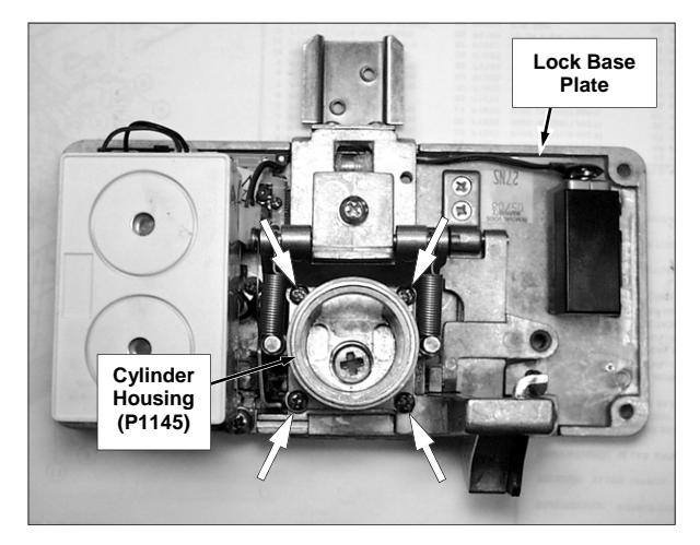
Fig. 3: The Lock Base Plate assembly. The lock cylinder is not supplied as shown in this image. Remove 4 screws securing the Cylinder Housing (4 arrows).
Install lock cylinder (CER) with the keyway horizontal, facing the front of the lock as shown in Fig. 4 (below).
Single Door Installations (cont'd)
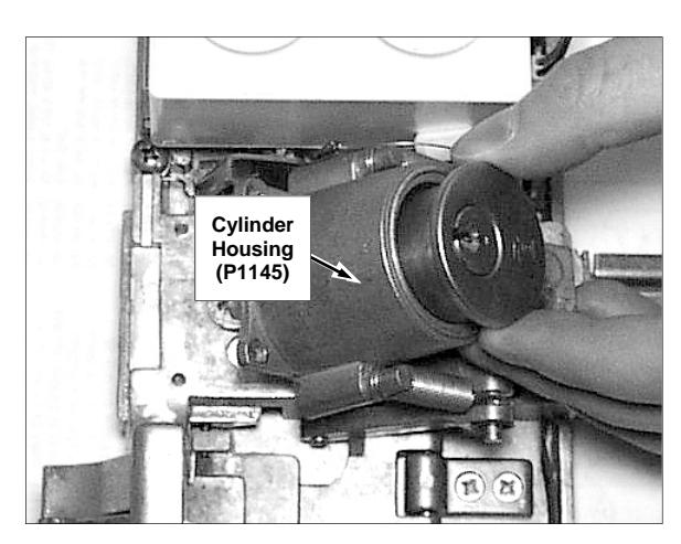
Fig. 4: Install lock cylinder (CER) with the keyway horizontal, facing the front of the lock (nine o'clock position) as shown.
Secure the lock cylinder to the Cylinder Housing (P1145) base with the two screws supplied with the lock cylinder (shown in Fig. 5). If needed, cut the cylinder Tailpiece 3/8" beyond the Cylinder Housing base. Replace the Cylinder Housing by guiding the Tailpiece into the Cam Crosshole , then re-secure the Cylinder Housing to the Lock Base Plate assembly with the four screws removed in step 3.
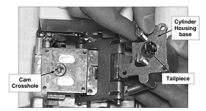
Fig. 5: Secure the lock cylinder to the Cylinder Housing base with two screws as shown. The Tailpiece must extend beyond the base of the Cylinder Housing and must fit into the Cam Crosshole .
4. TEST THE DEADBOLT
Use the key to test for proper operation of the deadbolt. Turn the key counter-clockwise to project the deadbolt and turn the key clockwise 360° to retract the deadbolt. The key should be able to be withdrawn from the lock cylinder in either the fully projected ("locked") or fully retracted ("unlocked") position of the deadbolt.
If the key cannot be withdrawn, the lock cylinder and the Cam are mis-aligned. Remove the four (4) screws securing the Cylinder Housing to the Lock Base Plate assembly as shown in Fig. 3, turn the Cam a quarter turn clockwise, then re-secure the Cylinder Housing . Re-test the deadbolt.
5. ATTACH PUSH BAR ASSY (Models 700 / 710 only)
See Fig. 6. Use the 1/8" Hex Wrench (supplied) to remove the Hex Screw (SC636), the small Lock Washer (WA136) and the Stiffening Washer (WA201) from the Clapper Arm-Hinge Bkt (P5022).
Place the Push Bar Assy on top of the Clapper Arm-Hinge Bkt , and place the Stiffening Washer on top of the Push Bar Assy as shown. Secure with the small Lock Washer and Hex Screw as shown in Fig. 6.
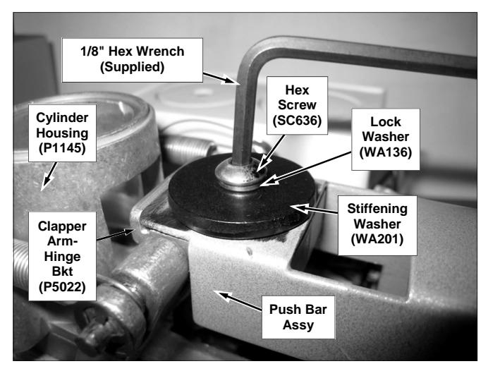
Fig. 6: Place the Push Bar Assy on top of the Clapper Arm-Hinge Bkt , and place the Stiffening Washer on top of the Push Bar Assy . Secure with the small Lock Washer and Hex Screw as shown.
See Fig. 7. Carefully turn the Lock Base Plate assembly over, and secure the Push Bar Assy to the Channel/Retaining Bracket (P5017) using two #10-24 x 1/2" Phillips flat head undercut zinc plated machine screws (P5460).
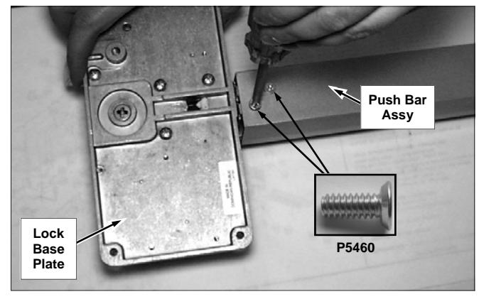
Fig. 7: secure the Push Bar Assy to the Channel/Retaining Bracket (P5017) using two #10-24 x 1/2" Phillips flat head undercut zinc plated machine screws (P5460).
6. SECURE LOCK BASE PLATE TO DOOR
Align the Lock Base Plate (with its attached Push Bar Assy ) with the holes drilled in step 2. Use the fol-
Single Door Installations (cont'd)
lowing screws to secure the Lock Base Plate to the door (Do NOT tighten fully at this time):
For WOOD DOORS
#10 x 1-3/4" Phillips Pan Head, Zinc Plated
For Hollow METAL DOORS
#10-24 x 1" Phillips Pan Head, Stainless Steel, Type F Thread Cutting
Separate the End Cap (P5034) from its Retaining Bracket (P5045).
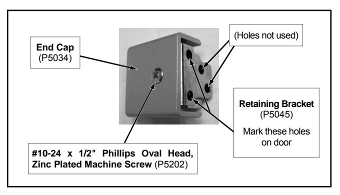
Fig. 8: The End Cap is secured to the Retaining Bracket at the factory.
7. SECURE PUSH BAR ASSY TO DOOR
Hold the end of the Push Bar Assy horizontally against the door using a level. Slide the Retaining Bracket (P5045) into the end of the Push Bar Assy . Using the Retaining Bracket as a template, mark two holes on the door as shown in Fig. 8 and Fig. 9. Be sure to mark the correct holes.
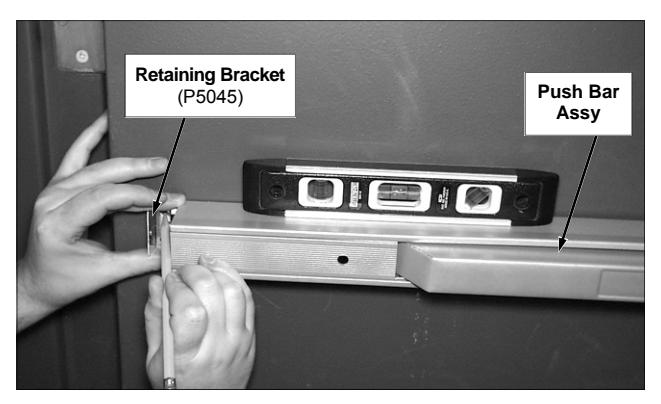
Fig. 9: Using the Retaining Bracket as a template, mark two holes on the door. Use a level to ensure the Push Bar Assy is horizontal.
door and use the following screws to secure the Re- taining Bracket to the door.
Note: If the Push Bar Assy is too long for the door, cut the end of the Channel Insert (P5046) and Base Channel (P5011) to the proper length and remove burrs from the edges.
For WOOD DOORS
#10 x 3/4" Phillips Pan head, Zinc Plated
For Hollow METAL DOORS
#10-24 x 5/8" Phillips Pan Head, Stainless Steel, Type F Thread Cutting
Mount the End Cap to the Retaining Bracket and secure with a #10-24 x 1/2" Phillips Oval Head, Zinc Plated Machine Screw (P5202) provided (see Fig. 8 and Fig. 10).
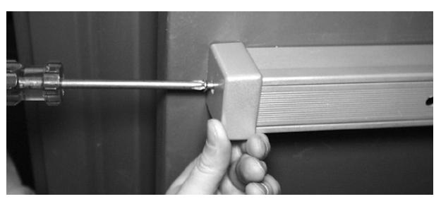
Fig. 10: Mount the End Cap.
8. TIGHTEN THE LOCK BASE PLATE
Fully tighten and secure the Lock Base Plate to the door. Do NOT install the Lock Cover (P5014) at this time.
9. SINGLE DOOR KEEPER INSTALLATION
Before drilling holes for the single door Keeper Base (P1157) in the surface of the doorframe, select the correct screws as follows:
For WOOD Doorframes
#10 x 1-1/2" Flat head, Phillips Zinc Plated (four count)
For Hollow METAL Doorframes
#10-24 x 5/8" Machine Screw, Phillips Flat Head, Type F Thread Cutting Stainless Steel (four count)
Single Door Installations (cont'd)
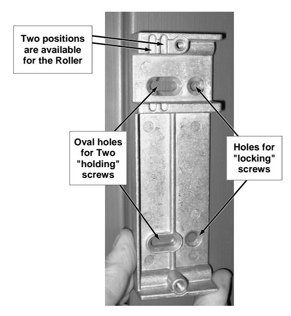
Fig. 11: Install the Keeper Base (P1157). Do not drill the holes for the "locking" screws until the Keeper Base is adjusted correctly.
Keeper Overview
In general, the Keeper Base (P1157) should be installed as close to the edge of the door jamb as possible, in keeping with the measurements on the template, to hold the door tightly latched, thus minimizing door rattle .
To allow side-to-side ("forward to back") adjustment of the Keeper Base , as shown in Fig. 11, two "holding screws" are to be inserted loosely into the Keeper Base oval holes (as shown on the template).
Important: Only after the Keeper Base position is finalized should the "locking" screw round holes be drilled.
Adjustable "Roller"
In addition to the side-to-side ("forward to back") adjustability provided by the oval "holding screw" holes, two positions are available for the Roller (P1171 and P1937).
The single door Keeper is shipped from the factory with its Keeper Cover (P0248) installed, holding the installed Roller in place. When the Keeper Cover is removed, notice the Roller (and its Pin ) have two available positions, "forward" (closer to the closing latch) and "rear" (further from the closing latch). The standard position is "forward", and initial adjustments should be made with the Roller installed in this position.
Installation
a. Close the door and verify the correct height position of the Keeper Base with respect to the latch. As shown on the template, drill two .157" (5/32") diameter holes for the two "holding screws" (oval holes).
- b. Remove the Keeper Cover from the Keeper Base by unscrewing its two screws.
- c. With the Keeper Base positioned against the door jamb, insert the appropriate screws into the oval holes of the Keeper Base . To allow side-to-side ("forward to back") adjustment of the Keeper Base , do NOT tighten these screws yet.
- d. Close the door, project the deadbolt and adjust the Keeper Base so that the door is tightly latched. Retract the deadbolt, hold the Keeper Base , release the latch and open the door. Tighten the two "holding" screws.
If you cannot get the door to be held tightly latched against the Keeper Base , it might be necessary to move the Roller into its "rear" position (further from the closing latch).
Recheck the position of the Keeper Base as many times as necessary to ensure the door is tightly latched . Ensure the deadbolt, when extended, floats within the rectangular deadbolt hole created when the Keeper Cover is installed into the Keeper Base .
As stated earlier, do NOT drill the "locking" screw (round holes) in the Keeper Base until the Keeper Base position is finalized.
- e. When the Keeper Base position is finalized, drill two .157" (5/32") diameter holes, as shown on template, for the "locking" screws. Insert the appropriate screws into the round "locking" holes of the Keeper Base , and tighten the screws to securely fasten the keeper to the door jamb.
- f. Install the Keeper Cover on the Keeper Base by screwing in its two screws (Part # SC413; #8-32 x 5/8" Machine Screw, Phillips Flat Head, Zinc Plated).
10. FINALIZING THE INSTALLATION
Ensure the 9-volt battery is installed and its plug is inserted into the lock Sub-Ass'y PCB (printed circuit board). Secure the Lock Cover with four #6- 32 x 1/4" Phillips Truss Head, Zinc Plated screws.
Secure the Lock Cover
#6-32 x 1/4" Phillips Truss Head, Zinc Plated (four count)

Double Door Installations
DOUBLE DOOR INSTALLATIONS
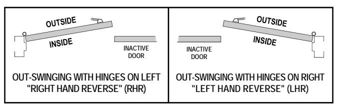
Fig. A: Cross Section Top View -- Door Hand.
See Fig. A to determine the door handing type for your installation. All models are non-handed and can be used for single or double-door installations. For single door installations, stop here and turn to page 3. The instructions that follow illustrate a typical installation of a model 700 / 710 to a "right-hand reverse" double door.
1. POSITION THE TEMPLATE
The template positions the lock body relative to the inactive door. ( Note: The gap between the active door and inactive door cannot exceed 5/8" or the latchbolt will not catch within the Keeper Assembly and the door will not lock).
With the door closed, carefully tape the template to the inside surface of the active and inactive doors so that the hole for the rim cylinder is about 38" above the floor. Place the dotted line on the template on the edge of the active door. See Fig. B.
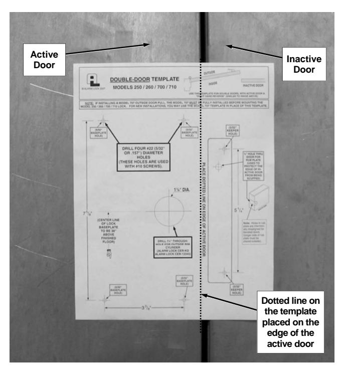
Fig. B: With door closed, tape the template to the inside surface of the active and inactive doors 38" above floor from the mark indicated on the template. Place the dotted line on the template on the edge of the active door
2. MARK AND DRILL THE HOLES
Compare holes referenced on the template (P5026) with holes described in the text below. Drill slowly and STRAIGHT through the door. Reposition the template as often as needed until it is placed correctly.
-
a. Mark six (6) .157" (5/32") diameter holes, four (4) for the Lock Base Plate and two (2) (of the three shown on template) for the Keeper Assembly.
- Note: For mounting onto a narrow-stile glass door, drill only two holes for the Lock Base Plate, along the jamb edge.
- b. IF OUTSIDE CYLINDER (MODEL CER-OKC) IS USED: Mark the center of the 11/4" diameter hole.
- c. IF OUTSIDE PULL (MODEL 707) IS USED : Use the door pull template (P3191). Mark the center of the four (4) ¼" diameter holes. Then proceed as follows:
For solid wood doors:
- 1. Drill 1/4" diameter through-hole.
- 2. From outside of door, use through-hole drilled in previous step to drill a 5/8" diameter hole to a depth of 11/4" only.
For hollow metal doors:
- 1. Drill ¼" diameter through-hole.
- 2. From outside of door, use through-hole drilled in previous step to drill a 5/8" diameter hole in outer metal skin only.
3. INSTALL LOCK CYLINDER (Not supplied)
Remove the Lock Cover . Remove the four (4) screws securing the Cylinder Housing (P1145) to the Lock Base Plate assembly as shown in Fig. C.
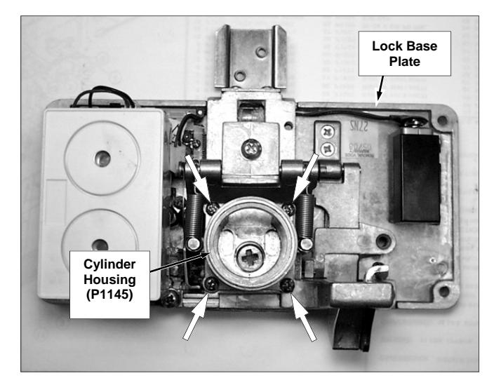
Fig. C: The Lock Base Plate assembly. The lock cylinder is not supplied as shown in this image. Remove 4 screws securing the Cylinder Housing (4 arrows).
Install lock cylinder (CER) with the keyway horizontal, facing the front of the lock as shown in Fig. D (below).
Double Door Installations (cont'd)
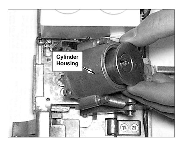
Fig. D: Install lock cylinder (CER) with the keyway horizontal, facing the front of the lock (nine o'clock position) as shown.
Secure the lock cylinder to the Cylinder Housing (P1145) base with two screws (supplied with the lock cylinder) as shown in Fig. E. If needed, cut the cylinder Tailpiece 3/8" beyond the Cylinder Housing base. Replace the Cylinder Housing by guiding the Tailpiece into the Cam Crosshole , then re-secure the Cylinder Housing to the Lock Base Plate assembly with the four (4) screws removed in step 3.
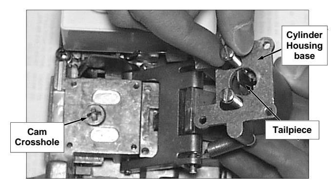
Fig. E: Secure the lock cylinder to the Cylinder Housing base with two screws as shown. The Tailpiece must extend beyond the base of the Cylinder Housing and must fit into the Cam Crosshole .
4. TEST THE DEADBOLT
Use the key to test for proper operation of the deadbolt. Turn the key counter-clockwise to project the deadbolt and turn the key clockwise 360° to retract the deadbolt. The key should be able to be withdrawn from the lock cylinder in either the fully projected ("locked") or fully retracted ("unlocked") position of the deadbolt.
If the key cannot be withdrawn, the lock cylinder and the Cam are mis-aligned. Remove the four (4) screws securing the Cylinder Housing (P1145) to the Lock Base Plate assembly as shown in Fig. C, turn the Cam a quarter turn clockwise, then re-secure the Cylinder Housing . Re-test the deadbolt.
5. ATTACH PUSH BAR ASSY (Models 700 / 710 only)
See Fig. F. Use the 1/8" Hex Wrench (supplied) to remove the Hex Screw (SC636), the small Lock Washer (WA136) and the Stiffening Washer (WA201) from the Clapper Arm-Hinge Bkt (P5022).
Place the Push Bar Assy on top of the Clapper Arm-Hinge Bkt , and place the Stiffening Washer on top of the Push Bar Assy as shown. Secure with the small Lock Washer and Hex Screw as shown in Fig. F.
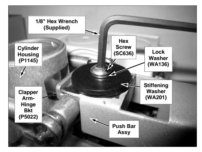
Fig. F: Place the Push Bar Assy on top of the Clapper Arm-Hinge Bkt , and place the Stiffening Washer on top of the Push Bar Assy . Secure with the small Lock Washer and Hex Screw as shown.
See Fig. G. Carefully turn the Lock Base Plate assembly over, and secure the Push Bar Assy to the Channel/ Retaining Bracket (P5017) using two #10-24 x 1/2" Phillips flat head undercut zinc plated machine screws (P5460).
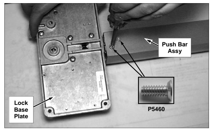
Fig. G: secure the Push Bar Assy to the Channel/Retaining Bracket (P5017) using two #10-24 x 1/2" Phillips flat head undercut zinc plated machine screws (P5460).
6. SECURE LOCK BASE PLATE TO DOOR
Align the Lock Base Plate (with its attached Push Bar Assy ) with the holes drilled in step 2. Use the following screws to secure the Lock Base Plate to the door (Do NOT tighten fully at this time):
Double Door Installations (cont'd)
For WOOD DOORS
#10 x 1-3/4" Phillips Pan Head, Zinc Plated
For Hollow METAL DOORS
#10-24 x 1" Phillips Pan Head, Stainless Steel, Type F Thread Cutting
Separate the End Cap (P5034) from its Retaining Bracket (P5045).

Fig. H: The End Cap is secured to the Retaining Bracket at the factory.
7. SECURE PUSH BAR ASSY TO DOOR
Hold the end of the Push Bar Assy horizontally against the door using a level. Slide the Retaining Bracket (P5045) into the end of the Push Bar Assy . Using the Retaining Bracket as a template, mark two holes on the door as shown in Fig. H and Fig. I. Be sure to mark the correct holes.
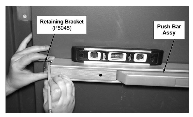
Fig. 1: Using the Retaining Bracket as a template, mark two holes on the door. Use a level to ensure the Push Bar Assy is horizontal.
Drill two .157" (5/32") diameter mounting holes into the door and use the following screws to secure the Retaining Bracket to the door.
Note: If the Push Bar Assy is too long for the door, cut the end of the Channel Insert (P5046) and Base Channel (P5011) to the proper length and remove burrs from the edges.
For WOOD DOORS
#10 x 3/4" Phillips Pan head, Zinc Plated
For Hollow METAL DOORS
#10-24 x 5/8" Phillips Pan Head, Stainless Steel, Type F Thread Cutting
Mount the End Cap to the Retaining Bracket and secure with a #10-24 x 1/2" Phillips Oval Head, Zinc Plated Machine Screw (P5202) provided (see Fig. H and Fig. J).
Fig. J: Mount the End Cap.
8. TIGHTEN THE LOCK BASE PLATE
Fully tighten and secure the Lock Base Plate to the door. Do NOT install the Lock Cover (P5014) at this time.
9. INSTALL THE RUB PLATE
Examine the template and physical parts
On the Double-Door Template (P5026), find the 5/32" Keeper Holes ; observe that these two holes are used to mark the screws that secure the Double-Door Keeper Base to the inactive door. The third hole on the tem-
plate is used to mark the Rub Plate "through-hole". Notice that the Rub Plate through-hole on the template is, by coincidence, located directly under the screw that secures the Black Nylon Insert to the Double-Door Keeper Base. Be aware that the Rub Plate "through-hole" and the Black Nylon Insert screw hole are used for two separate purposes:
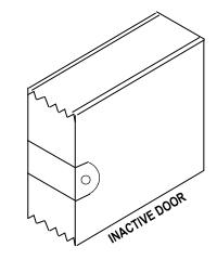
Fig. K: Rub Plate.
- The Rub Plate is used to protect the edge of the inactive door from being scuffed by the latchbolt as shown in Fig. K.
- The black nylon insert (see Fig. L) is used to prevent the locked active door from rattling and is adjusted with the Double-Door Keeper Base secured and the deadbolt projected.
Double Door Installations (cont'd)
Install the Rub Plate
Install the Rub Plate for a 1¾" wide door. Note that the holes in the Rub Plate are intentionally misaligned (and the sides are of different lengths) in order to fit beveled doors (the longer side of the Rub Plate is placed outside). The Rub Plate through-hole location is marked indicated on the template; drill a ¼" through-hole straight through the door and secure the Rub Plate with the 10-32 screw and nut bushing provided (be sure to place this unslotted nut bushing on the outside door surface).
10. INSTALL THE MODEL 732 KEEPER
Before drilling holes for the Double Door Keeper ( Model 732 ) in the surface of the inactive door, select the correct screws as follows:
For WOOD Doorframes
#10 x 1-1/2" Flat head, Phillips Zinc Plated (four count)
For Hollow METAL Doorframes
#10-24 x 5/8" Machine Screw, Phillips Flat Head, Type F Thread Cutting Stainless Steel (four count)
When the Double Door Keeper Base position is finalized, drill two .157" (5/32") diameter holes, as shown on template, for the "locking" screws. Insert the appropriate screws into the round "locking" holes of the Double Door Keeper Base , and tighten the screws to securely fasten the keeper to the door jamb.
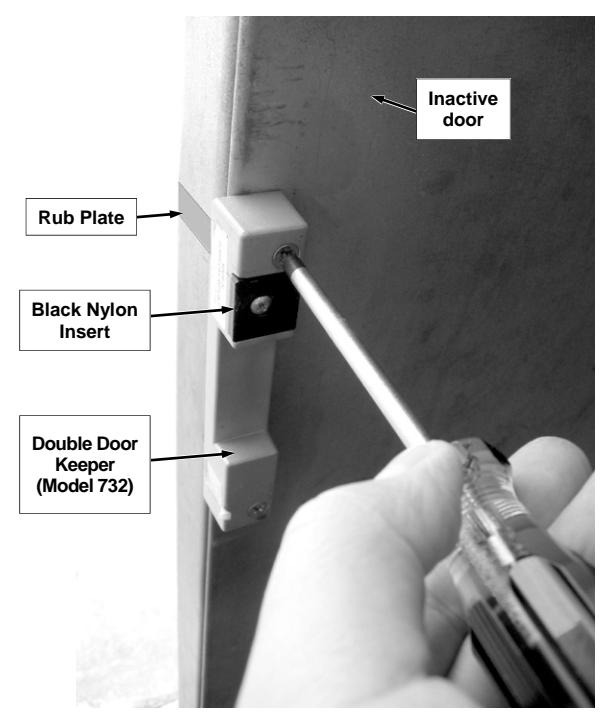
Fig. L: Install the Double Door Keeper (Model 732) on the inactive door. Note the location of the Black Nylon Insert and installed Rub Plate .
11. ADJUST THE BLACK NYLON INSERT
Close the door, project the deadbolt and adjust the Black Nylon Insert on the Double Door Keeper Model 732 by loosening its hold-down screw and sliding the nylon insert against the lock latchbolt so the door is tightly latched and is free from rattle.
12. FINALIZING THE INSTALLATION
Ensure the 9-volt battery is installed and its plug is inserted into the lock Sub-Ass'y PCB (printed circuit board). Secure the Lock Cover with four #6-32 x 1/4" Phillips Truss Head, Zinc Plated screws.
Secure the Lock Cover
#6-32 x 1/4" Phillips Truss Head, Zinc Plated (four count)

WATERPROOF MODELS
The waterproof models are basically identical to the standard models, except the waterproof models are specifically designed for outdoor applications. Weather-resistant for exposure to rain make them appropriate for use even in harsh conditions. In addition, the waterproof models are powered with a long-life 9VDC sealed alkaline battery pack (use part # S6173 only). These models include:
- 250WP ··· Clapper Plate Waterproof
- 700WP ··· Channel Push Bar Waterproof
- 710WP ··· Channel Push Bar Retriggerable Waterproof
Operating Instructions -- All Locks
OPERATING INSTRUCTIONS BEFORE INSTALLING THE LOCK COVER:
- 1. Select either:
- Continuous Alarm Leave the black jumper plug on the terminal strip, as installed.
- Auto-Alarm Shutdown Remove the black jumper plug from the terminal strip.
- 2. Connect the battery connector to the 9-volt battery observing the proper polarity. A short beep will sound ensuring that the lock is powered and ready.
- 3. Install the Lock Cover with four #6-32 x 1/4" Phillips Truss Head, Zinc Plated screws.
- 4. Close the door.
OPERATIONAL TESTING
- 1. Lock and unlock the door using the cylinder key and note a small beep sounds when the deadbolt is retracted, indicating a disarmed condition. The door can now be opened without an alarm, by pushing the Clapper Plate or the Push Bar Assy .
- 2. Lock the door again and push the Clapper Plate (or Push Bar Assy ) to open the door. Immediately the alarm pulses loudly and one of the following occurs:
- If Continuous Alarm was selected, the alarm will sound until the lock is manually reset by locking the deadbolt with the key.
- If Auto-Alarm Shutdown was selected, the alarm will sound for two minutes, then reset.
LOW BATTERY DETECTION
When the battery is weak, the sounder emits a short beep approximately once every minute. Always replace weak batteries as soon as possible. To access the 9-volt battery, remove the Lock Cover by unscrewing four #6-32 x 1/4" Phillips Truss Head, Zinc Plated screws.
DOGGING OPERATION
Insert the 3/16" L-shaped hexagonal Allen wrench (provided) into the dogging latch through the hole in the channel insert. Turn the dogging latch counterclockwise ½ turn, push in the Push Bar Assy (or Clapper Plate ), and turn the dogging latch clockwise ¼ turn until it stops. Release the Push Bar Assy . The Push Bar Assy remains depressed when the lock is unlatched.
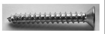
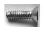
SCREW CHART
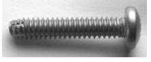
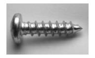
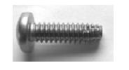
| LOCATION | DESCRIPTION | IMAGE | SIZE SPECS |
|---|---|---|---|
|
Secures the Lock Base
Plate Assembly to a SOLID WOOD DOOR |
(Part # P1677) #10 x 1-
3/4" Phillips Pan Head, Zinc Plated (four count) |
||
|
Secures the Lock Base
Plate Assembly to a HOLLOW METAL DOOR |
(Part # SC616LF) #10-24
x 1" Phillips Pan Head, Stainless Steel, Type F Thread Cutting (four count) |
||
|
Secures the Push
Bar Assy to the Channel/ Retaining Bracket (P5017) |
(Part # P5460) #10-24 x
1/2" Phillips Flat Head, Undercut, Machine Screw, Zinc Plated (two count) |
||
|
Connects the Push Bar
and Channel Assembly to the Clapper Arm Hinge |
(Part # SC636) 10-32 x
1/2" Button Head Socket Cap Screw, Stainless Steel, use Allen wrench (1/8") to tighten (one count) |
||
|
Secures Retaining Brack
et to a SOLID WOOD DOOR |
(Part # P1671) #10 x 3/4"
Phillips Pan head, Zinc Plated (two count) |
||
|
Secures Retaining Brack
et to a HOLLOW MET AL DOOR |
(Part # SC617LF) #10-24
x 5/8" Phillips Pan Head, Stainless Steel, Type F Thread Cutting (two count) |
||
|
Mounts End Cap to Re
taining Bracket |
(Part # P5202) #10-24 x
1/2" Phillips Oval Head, Zinc Plated Machine Screw |
SCREW CHART (Cont'd)
| LOCATION | DESCRIPTION | IMAGE | SIZE SPECS |
|---|---|---|---|
|
Secures the SINGLE Door
Keeper Base to a SOLID WOOD DOOR |
(Part # P1676) #10 x 1-
1/2" Flat head, Phillips Zinc Plated (four count) |
||
|
Secures the SINGLE Door
Keeper Base to a HOLLOW METAL DOOR |
(Part # SC618) #10-24 x
5/8" Machine Screw, Phillips Flat Head, Type F Thread Cutting Stain less Steel (four count) |
||
|
Secures the DOUBLE Door
Keeper Base to a SOLID WOOD DOOR |
(Part # P1676) #10 x 1-
1/2" Flat head, Phillips Zinc Plated (four count) |
||
|
Secures the DOUBLE Door
Keeper Base to a HOLLOW METAL DOOR |
(Part # SC618) #10-24 x
5/8" Machine Screw, Phillips Flat Head, Type F Thread Cutting Stain less Steel (four count) |
||
|
Secures the Cover for the
SINGLE Door Keeper Base |
(Part # SC413) #8-32 x
5/8" Machine Screw, Phillips Flat Head, Zinc Plated (two count) |
||
|
Mounts Lock Cover to Lock
Base Plate assembly. |
(Part # P1508) #6-32 x
1/4" Phillips Truss Head, Zinc Plated (four count) |
DETAIL ASSEMBLY OF 700 & 710 SERIES
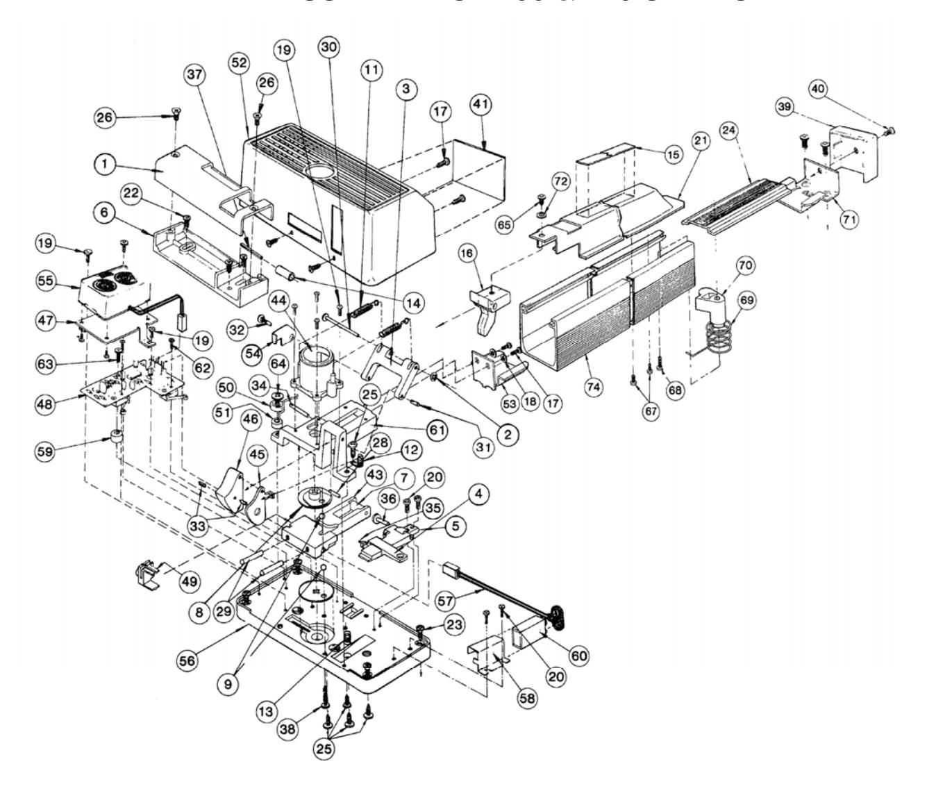
Important: Exploded view and part numbers below do NOT fully apply to waterproof "WP" models.
| DES PART # DESCRIPTION | 24 P5046 CHANNEL INSERT | 51 P5030 TENSION SPRING SPACER |
|---|---|---|
| 1 P0248 KEEPER COVER | 25 SC617LF 10-24X5/8 PHIL PAN STF ST LSS | 52 P5014 LOCK COVER (ALUM) |
| 1 P0248G-312E KEEPER COVER MTLLIC BROWN* | 26 SC413 8-32 X 5/8 MS ZINC PLT | 53 P5017 CHANNEL/RETAINING BRACKET |
| 2 P1140 (PART OF S5251 ASS'Y) | 27 P5100 CHANNEL INSERT (DURANODIC)* | 54 P5054 (PART OF S5252 ASS'Y) |
| 3 P5093 (PART OF S5252 ASS'Y) | 28 P1927 (PART OF S3113 ASS'Y) | 55 HW908LF PIEZO W/MOUNTING BRKT ASSY |
| 4 P1151 (PART OF S3120 ASS'Y) | 29 P1928 (PART OF S3113 ASS'Y) | 56 P5063 LOCK BASE PLATE |
| 5 HW1607 (PART OF S3120 ASS'Y) | 30 P1929 (PART OF S5251 ASS'Y) | 57 9S5229ASSY BATTERY CONNECTOR |
| 6 P1157 KEEPER BASE | 31 P1930 (PART OF S5252 ASS'Y) | 58 P5077 BATTERY CLAMP BKT. |
| 7 P1158 (PART OF S3113 ASS'Y) | 32 P1931 (PART OF S5252 ASSY) | 59 P5089 SPACER, NYLON 1/4 L |
| 8 P1159 (PART OF S3114 ASS'Y) | 33 P1932 (PART OF S5252 ASS'Y) | 60 P5103 BATTERY, 9-VOLT |
| 9 P1160 (PART OF S3114 ASS'Y) | 34 P1933 (PART OF S5252 ASS'Y) | 61 P5121 (PART OF S5252 ASS'Y) |
| 11 P1168 (PART OF S5252 ASS'Y) | 35 P1934 (PART OF S3120 ASS'Y) | 62 P5195 2-56 X 1/2 L PH PHIL. |
| 12 P1169 LATCH TRIP SPRING | 36 P1935 (PART OF S3120 ASS'Y) | 63 P5195 2-56 X 1/2 L PH PHIL. |
| 13 P1170 D'LOCK LEVER SPRING | 37 P1937 (PART OF ROLLER) | 63 SC604 2-56 X 1/2 MS PHIL PAN STNLSS (WP) |
| 14 P1171 (PART OF ROLLER) | 38 P4155 10-24 X 5/8 PH PHIL. | 64 SC465 10 X 3/4 PH PHIL TYPE 23 |
| 15 P5023 LABEL-PUSH BAR | 39 P5034 END CAP | 64 SC605 10 X 3/4 PHIL PAN T23 STNLSS (WP) |
| 16 P5022 CLAPPER ARM-HINGE BKT. | 40 P5202 10-24 X 1/2 L OVAL HD. PHIL. | 65 SC636 BUTTN HD HEX 1/8" 10-32 X 1/2 SS |
| 17 P1508 6-32 X 1/4 L TRUSS HD. | 41 P5233 PROD-LABEL 700/710 | 66 P5099 BASE CHANNEL (DURANODIC)* |
| 18 WA143 INTERNAL LOCKWASHER | 42 P5110 LOCK COVER (DURANODIC)* | 67 P1735 10-32 X 3/8L PH PHIL |
| 19 P1520 (PART OF HW908LF; SEE #55) | 43 P1143 (PART OF S3113 ASS'Y) | 68 P5204 (PART OF S5253 ASSY) |
| 20 SC466 6 X 3/8 SELF TAP, PH PHIL. | 44 P1145 (PART OF S5252 ASS'Y) | 69 P5048 (PART OF S5253 ASSY) |
| 21 P5010 PUSH BAR & ASSY | 45 P1149 (PART OF S5252 ASS'Y) | 70 P5047 (PART OF S5253 ASSY) |
| 22 P1676 (WOOD MOUNTING SCREW) | 46 P1150 (PART OF S5252 ASS'Y) | 71 P5045 RETAINING BKT. |
| 22 SC618 (METAL MOUNTING SCREW) | 47 P5012 (PART OF HW908LF; SEE #55) | 72 P5201 LOCKWASHER #10 INT STAR ZINC |
| 22 SC618 10-24 X 5/8", PHIL FLT HD TYPE F STNLS | 48 SUB-ASS'Y PCB (VARIES WITH MODEL) | 73 P5109 END CAP (DURANODIC)* |
| 23 P1677 (WOOD MOUNTING SCREW) | 49 P5019 CAM FOLLOWER | 74 P5011 BASE CHANNEL |
| 23 SC616LF (METAL MOUNTING SCREW) | 50 P5422 TENSION SPRING | 75 P5108 PUSH BAR & ASS'Y (DURANODIC)* |
* Optional parts available. Contact your sales representative for more information.
DETAIL ASSEMBLY OF 250 & 260 SERIES
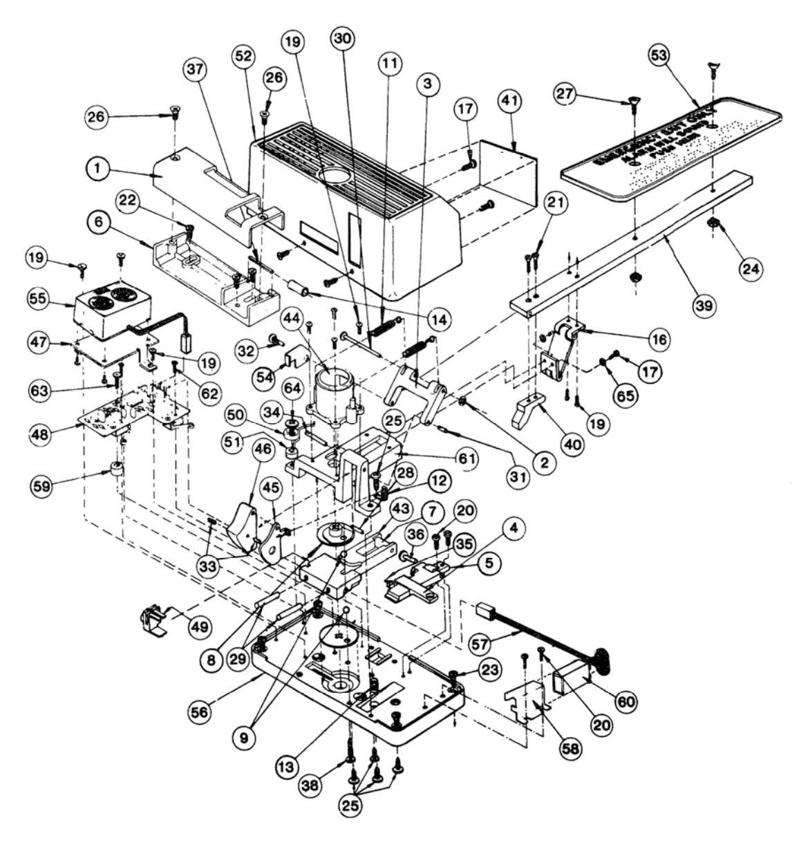
Important: Exploded view and part numbers below do NOT fully apply to waterproof "WP" models.
| # PART#DESCRIPTION | 22 P1676 (WOOD MOUNTING SCREW) | 44 . P1145 (PART OF S5252 ASS'Y) |
|---|---|---|
| 1 P0248KEEPER COVER | 22 SC618 (METAL MOUNTING SCREW) | 45 . P1149 (PART OF S5252 ASS'Y) |
| 1 P0248G-312EKEEPER COVER MTLLIC BROWN* | 23 P1677 (WOOD MOUNTING SCREW) | 46 . P1150 (PART OF S5252 ASS'Y) |
| 2 P1140(PART OF S5251 ASS'Y) | 23 SC616LF (METAL MOUNTING SCREW) | 47 . P5012 (PART OF HW908LF; SEE #55) |
| 3 P5093(PART OF S5252 ASS'Y) | 24 P1684 NUT 10-32 X 3/8 HEX. | 48 SUB-ASS'Y PCB (VARIES WITH MODEL) |
| 4 P1151(PART OF S3120 ASS'Y) | 25 SC617LF 10-24X5/8 PHIL PAN STF ST LSS | 49 . P5019 CAM FOLLOWER |
| 5 HW1607(PART OF S3120 ASS'Y) | 26 SC413 8-32 X 5/8 MS ZINC PLT | 50 . P5422 TENSION SPRING |
| 6 P1157KEEPER BASE | 27 P1748 10-32 X 3/4 L OVAL HD. | 51 . P5030 TENSION SPRING SPACER |
| 7 P1158(PART OF S3113 ASS'Y) | 28 P1927 (PART OF S3113 ASS'Y) | 52 . P5031 LOCK COVER (ALUM) |
| 8 P1159(PART OF S3114 ASS'Y) | 29 P1928 (PART OF S3113 ASS'Y) | 53 . P5050 CLAPPER PLATE |
| 9 P1160(PART OF S3114 ASS'Y) | 30 P1929 (PART OF S5251 ASS'Y) | 54 . P5054 (PART OF S5252 ASS'Y) |
| 11 P1168(PART OF S5252 ASS'Y) | 31 P1930 (PART OF S5252 ASS'Y) | 55 . HW908LF PIEZO W/MOUNTING BRKT ASSY |
| 12 P1169LATCH TRIP SPRING | 32 P1931 (PART OF S5252 ASSY) | 56 . P5063 LOCK BASE PLATE |
| 13 P1170D'LOCK LEVER SPRING | 33 P1932 (PART OF S5252 ASS'Y) | 57 . 9S5229ASSY BATTERY CONNECTOR |
| 14 P1171(PART OF ROLLER) | 34 P1933 (PART OF S5252 ASS'Y) | 58 . P5077 BATTERY CLAMP BRACKET |
| 15 P1250CLAPPER PLATE (LONG)* | 35 P1934 (PART OF S3120 ASS'Y) | 59 . P5089 SPACER, NYLON 1/4 L |
| 16 P1260HINGE | 36 P1935 (PART OF S3120 ASS'Y) | 60 . P5103 BATTERY, 9-VOLT |
| 17 P15086-32 X 1/4 L TRUSS HD. | 37 P1937 (PART OF ROLLER) | 61 . P5121 (PART OF S5252 ASS'Y) |
| 18 P4545CLAPPER ARM | 38 P4155 10-24 X 5/8 PH PHIL. | 62 . P5195 SCREW. 2-56 X 1/2 L PH PHIL. |
| 19 SC5456-32 X 3/8, FLAT HD, TAPTITE, PHIL | 39 P4493 CLAPPER ARM | 63 . P5195 2-56 X 1/2 L PH PHIL. |
| 19 SC601(FOR WP MODELS) | 40 P4495 TRIGGER CAM | 63 . SC604 2-56 X 1/2 MS PHIL PAN STNLSS (WP) |
| 20 SC466 6 X 3/8 SELF TAP, PH PHIL. | 41 P5232 PROD-LABEL 250/260 | 64 . SC465 10 X 3/4 PH PHIL TYPE 23 |
| 21 SC413 8-32 X 5/8 MS ZINC PLT | 42 P5111 LOCK COVER (DURANODIC)* | 64 . SC605 10 X 3/4 PHIL PAN T23 STNLSS (WP) |
| 21 SC600 (FOR WP MODELS) | 43 P1143 (PART OF S3113 ASS'Y) | 65 . WA143 INTERNAL TOOTH LOCK WASHER |
* Optional parts available. Contact your sales representative for more information.
ALARM LOCK LIMITED WARRANTY
ALARM LOCK SYSTEMS, INC. (ALARM LOCK) warrants its products to be free from manufacturing defects in materials and workmanship for twenty four months following the date of manufacture. ALARM LOCK will, within said period, at its option, repair or replace any product failing to operate correctly without charge to the original purchaser or user.
This warranty shall not apply to any equipment, or any part thereof, which has been repaired by others, improperly installed, improperly used, abused, altered, damaged, subjected to acts of God, or on which any serial numbers have been altered, defaced or removed. Seller will not be responsible for any dismantling or reinstallation charges, environmental wear and tear, normal maintenance expenses, or shipping and freight expenses required to return products to ALARM LOCK. Additionally, this warranty shall not cover scratches, abrasions or deterioration due to the use of paints, solvents or other chemicals.
THERE ARE NO WARRANTIES, EXPRESS OR IM-PLIED, WHICH EXTEND BEYOND THE DESCRIPTION ON THE FACE HEREOF. THERE IS NO EXPRESS OR IMPLIED WARRANTY OF MERCHANTABILITY OR A WARRANTY OF FITNESS FOR A PARTICULAR PUR-POSE. ADDITIONALLY, THIS WARRANTY IS IN LIEU OF ALL OTHER OBLIGATIONS OR LIABILITIES ON THE PART OF ALARM LOCK.
Any action for breach of warranty, including but not limited to any implied warranty of merchantability, must be brought within the six months following the end of the warranty period.
IN NO CASE SHALL ALARM LOCK BE LIABLE TO ANY-ONE FOR ANY CONSEQUENTIAL OR INCIDENTAL DAMAGES FOR BREACH OF THIS OR ANY OTHER WARRANTY, EXPRESS OR IMPLIED, EVEN IF THE LOSS OR DAMAGE IS CAUSED BY THE SELLER'S OWN NEGLIGENCE OR FAULT.
In case of defect, contact the security professional who installed and maintains your security system. In order to exercise the warranty, the product must be returned by the security professional, shipping costs prepaid and insured to ALARM LOCK. After repair or replacement, ALARM LOCK assumes the cost of returning products under warranty. ALARM LOCK shall have no obligation under this warranty, or otherwise, if the product has been repaired by others, improperly installed, improperly used, abused, altered, damaged, subjected to accident, nuisance, flood, fire or acts of God, or on which any serial numbers have been altered, defaced or removed. ALARM LOCK will not be responsible for any dismantling, reassembly or reinstallation charges, environmental wear and tear, normal maintenance expenses, or shipping and freight expenses required to return products to ALARM LOCK. Additionally, this warranty shall not cover scratches, abrasions or deterioration due to the use of paints, solvents or other chemicals.
This warranty contains the entire warranty. It is the sole warranty and any prior agreements or representations, whether oral or written, are either merged herein or are expressly cancelled. ALARM LOCK neither assumes, nor authorizes any other person purporting to act on its behalf to modify, to change, or to assume for it, any other warranty or liability concerning its products.
In no event shall ALARM LOCK be liable for an amount in excess of ALARM LOCK's original selling price of the product, for any loss or damage, whether direct, indirect, incidental, consequential, or otherwise arising out of any failure of the product. Seller's warranty, as hereinabove set forth, shall not be enlarged, diminished or affected by and no obligation or liability shall arise or grow out of Seller's rendering of technical advice or service in connection with Buyer's order of the goods furnished hereunder.
ALARM LOCK RECOMMENDS THAT THE ENTIRE SYS-TEM BE COMPLETELY TESTED WEEKLY.
Warning: Despite frequent testing, and due to, but not limited to, any or all of the following; criminal tampering, electrical or communications disruption, it is possible for the system to fail to perform as expected. ALARM LOCK does not represent that the product/system may not be compromised or circumvented; or that the product or system will prevent any personal injury or property loss by burglary, robbery, fire or otherwise; nor that the product or system will in all cases provide adequate warning or protection. A properly installed and maintained alarm may only reduce risk of burglary, robbery, fire or otherwise but it is not insurance or a guarantee that these events will not occur. CONSEQUENTLY, SELLER SHALL HAVE NO LIA-BILITY FOR ANY PERSONAL INJURY, PROPERTY DAMAGE, OR OTHER LOSS BASED ON A CLAIM THE PRODUCT FAILED TO GIVE WARNING. Therefore, the installer should in turn advise the consumer to take any and all precautions for his or her safety including, but not limited to, fleeing the premises and calling police or fire department, in order to mitigate the possibilities of harm and/or damage.
ALARM LOCK is not an insurer of either the property or safety of the user's family or employees, and limits its liability for any loss or damage including incidental or consequential damages to ALARM LOCK's original selling price of the product regardless of the cause of such loss or damage.
Some states do not allow limitations on how long an implied warranty lasts or do not allow the exclusion or limitation of incidental or consequential damages, or differentiate in their treatment of limitations of liability for ordinary or gross negligence, so the above limitations or exclusions may not apply to you. This Warranty gives you specific legal rights and you may also have other rights which vary from state to state.