Alarm Lock PM600 PM1200 Wiring Instructions
Open the original PDF document
View PDFPM600BI PM1200 Wiring Instruction PM120040
Single Door Magnet
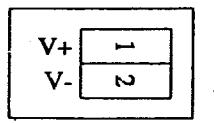
V+POWER IN DC 12V or 24V
PM600L PM1200S PM1200SL
PM1200SL40 PM1200SLBI
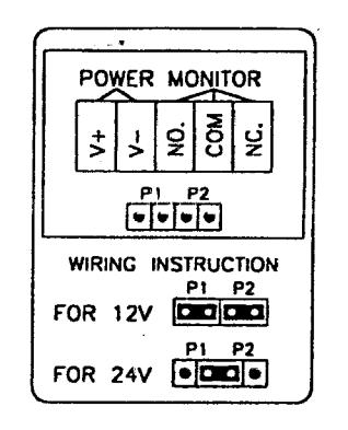
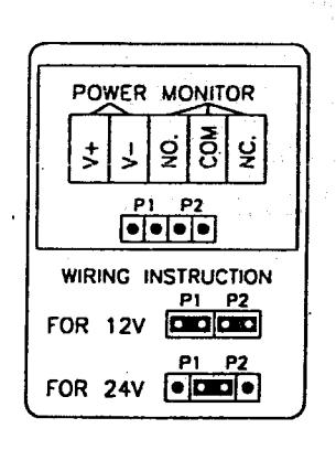
Wiring Instruction
Single Door magnet with Single monitor
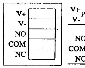
|
V+
V-POWER IN DC 12V or 24V |
|
|---|---|
| NO | |
| COM | DOOR MONITORING OUTPUT |
| NC | |
The Orientation of Magnet Black & Armature Plate
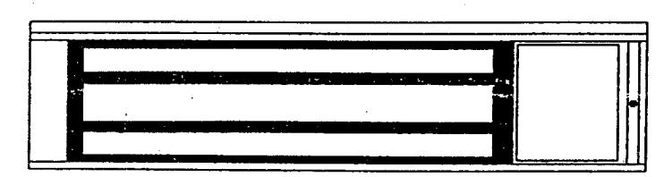
Plesae install the Magnet and Armature Plate as the drawing. Otherise, it may affect the Seansor output.
MAGNETIC LOCK MOUNTING INSTRUCTIONS
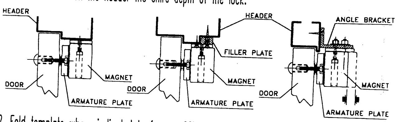
1. Note type of door frame header and install filler plate or angle bracket as required to provide a flat surface on the header the enire depth of the lock.
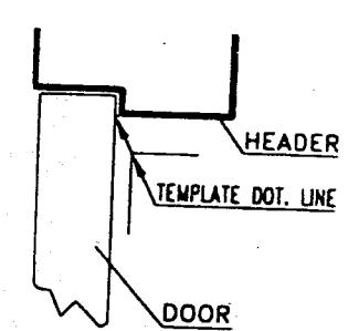
2. Fold template where indicated to from a 90° angle. For a swinging door place template against door header and door opposite hinge side of door jamb. For a pair of swinging doors place template against door and door header at center of door opening Transfer hole locations to door and door frame header.
3. Follow template instructions for hole size. Use the illustrations below to determine proper armature mounting hole preparation.
Solid Door
Hollow Metal Door
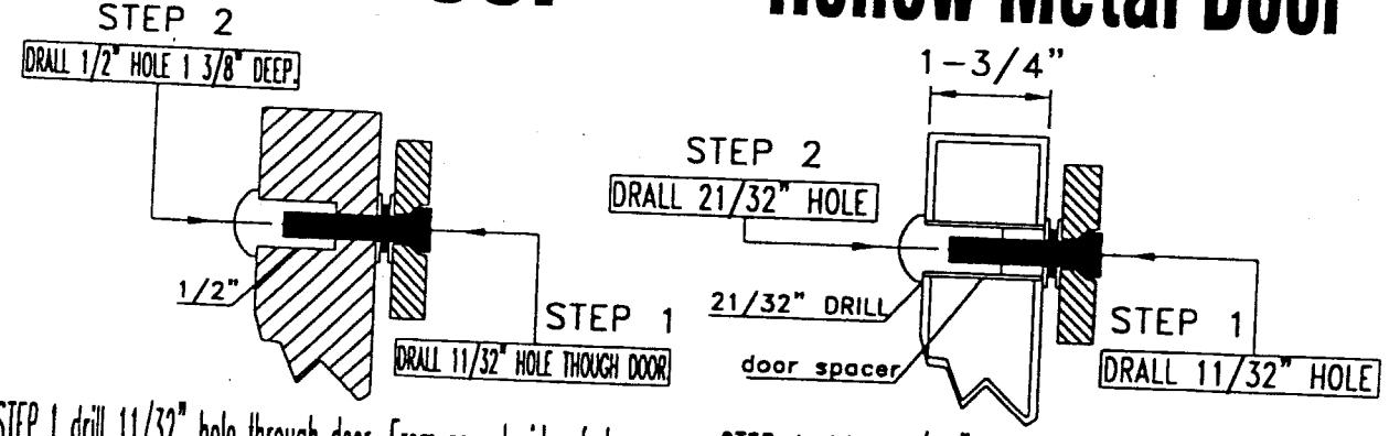
STEP 1 drill 11/32" hole through door. From sexnut side of door STEP 2 drill 1/2" dia. hole 1 3/8" deep. Mount armature to door with hardware provided.
STEP 1 drill 11/32" hole From sexnut side of door STEP 2 drill 21/32" hole through one metal thickness only. Mount armature to door with hardware provided.
4. Mount armature to door with hardware provided per illustrations. Remember to insert avida
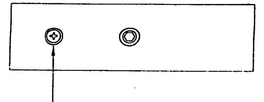
View of Mounting Plate Under the Header
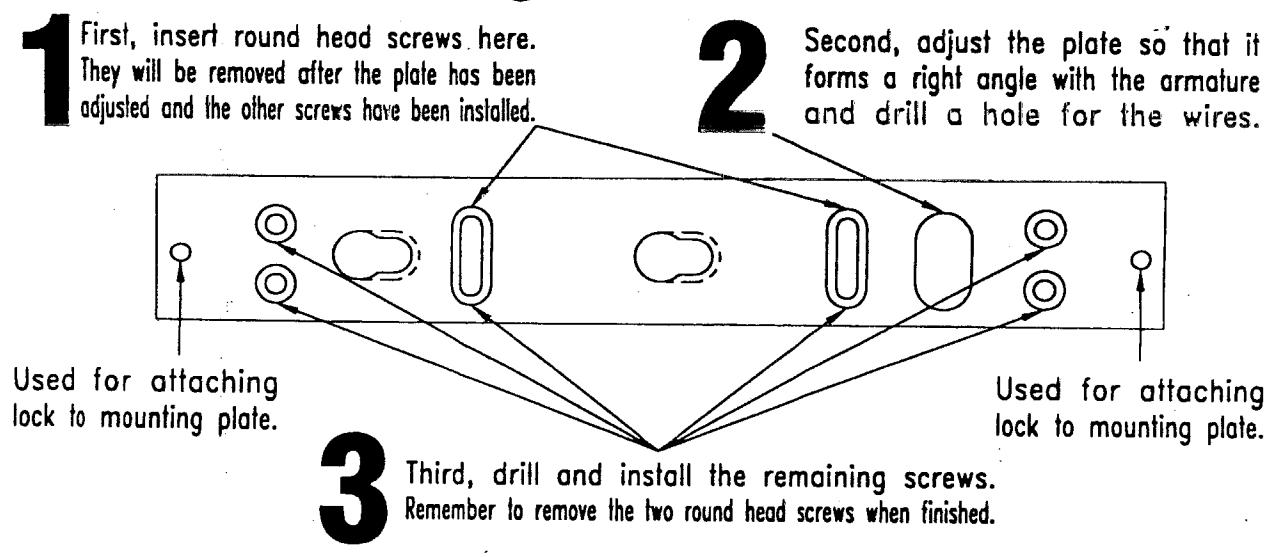
- 5. Install mounting plate to header with 2 round head screws(the two (2) round head screws are installed in the slotted holes for adjustment and will be removed before the magnet is installed.
- 6. Adjust the mounting plate so that it and the armature plate form a right angle.
- 7. Using the mounting plate as template, drill the wire hole.
- 8. Install the six (6) #10 flathead screws provided
- 9. Fasten the lock to mounting plate with the two (2)1/4-20 socket screws provided. Compensate for any misalignment by adding or subtracting washers at armature mounting screws.
- 10. Firmly tighten all screws. Install anti-tamper plugs into holes over each socket head mounting screw. Use soft hammer to avoid damaging lock case.
- 11. Rubber on armature screwhead must not be trimmed or modified for correct operation.
2000/08/30-2