Alarm Lock PL6100 Programming Instructions
Open the original PDF document
View PDF

345 Bayview Avenue, Amityville, New York 11701 For Sales and Repairs 1-800-ALA-LOCK For Technical Service 1-800-645-9440
or visit us at http://tech.napcosecurity.com/ (Note: Technical Service is for security professionals only) Publicly traded on NASDAQ Symbol: NSSC
Wireless Trilogy Networx™ PL6100 Programming Instructions
© ALARM LOCK 2017 WI1843BLF 8/17
DL-WINDOWS PROGRAMMING SOFTWARE
AL-IM2-PIE PLUG-IN EXPANDER MODULE
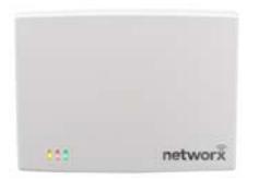
AL-IM2 SERIES "VERSION 2" GATEWAY MODULES
AL-IM2-80211 AL-IME2 AL-IME2POE

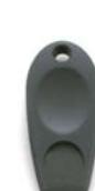
PROXIMITY KEYFOB
AL-PRE2 PROXCARD® READER / ENROLLER

CARD
PL Wireless Trilogy Series Network Access Control System with ProxCard® Access
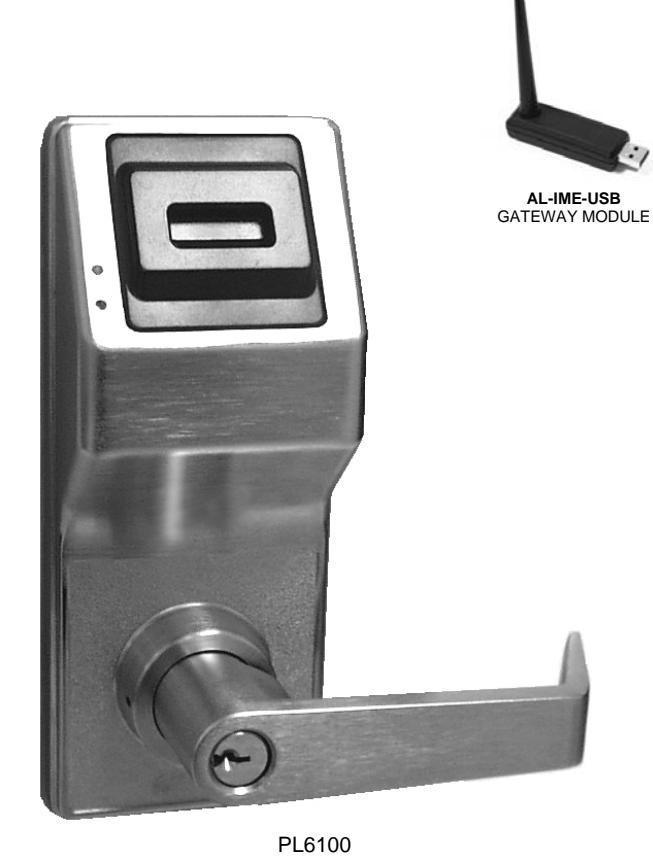
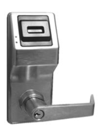
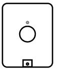
PL6100 WIRELESS LOCK
THE ALARM LOCK WIRELESS TRILOGY PL-SERIES STAND-ALONE ACCESS CONTROL SYSTEM IS A STATE-OF-THE-ART MICROPROCESSOR-BASED COMPUTER NETWORK PROGRAMMABLE PROXIMITY SECURITY LOCK.
PL6100
PL6100
The PL6100 is designed to allow all features to be programmed through its radio link from a DL-Windows-equipped computer. In addition, Audit Log Data may be transmitted through the radio link back to the DL-Windows computer.
To increase security, PL Series locks do not include a keypad; instead the PL6100 features an HID compatible ProxCard® reader.
In addition, data can be retrieved from the lock to your PC with DL-Windows software. Its real-time clock/calendar automatically adjusts for Daylight Saving Time and allows for automated programming of events.
Note: ProxCard® and ProxKey® are trademarks of the HID© Corporation.
Table of Contents
| Wireless PL Series Lock Features 3 | |
|---|---|
| Supported Products 4 | |
| Lock Design Overview 6 | |
| Terminology Used in this Manual 7-8 | |
| Wiring 9 | |
| First Time Power Up 9 | |
| Battery Replacement 9 | |
| Erase All Programming 10 | |
| Power UpRetain Existing Programming 10 | |
| Testing the Cards Entered 10 | |
| LED and Sounder Indicators 10 | |
| DL-Windows Programmable Features Screen 11-13 | |
| Emergency Commands 14-15 | |
| Wireless Remote Releases 16 | |
| User Card Record Sheet 17-18 | |
| Glossary 19 | |
| Limited Warranty 20 |
Wireless PL Series Lock Features
Audit Trail
- 40,000 Event Capacity
- Entries Logged with Time and Date
- Critical Programming Events Logged
- Uploadable using Alarm Lock's DL-Windows software
Lock Features
- Metal Key Override for all cylindrical locks
- Non-Volatile (Fixed) Memory
- Real-Time Clock, with automatic Daylight Saving Time adjust (see page 11)
- Programmable Relay (via DL-Windows only) (see pages 9 and 12)
- Visual and Audible Feedback (see page 10)
- Inside Emergency Indicator LED (see page 15)
- Battery Status Monitor (see pages 9 and 10)
Scheduling (Using DL-Windows)
- 500 Scheduled Events (see page 11)
- Automated Unlock/Lock (see pages 11 and 12)
- Enable/Disable Users (see page 7 for definition of "User")
- Enable/Disable Groups (see page 8 for definition of "Group")
- Real-time clock and calendar
User Access Methods
- ProxCard® and ProxKey® Keyfob
- Batch Enroll Quickly and easily enroll multiple ProxCards® and ProxKey® keyfobs without the use of a PC
Note: ProxCards® and ProxKey® Keyfobs both function identically
Global and Local Lock-Down activated from Wireless Remote Release Transmitters, DL-Windows or initiated from another Networx lock in the system (see "How do the Emergency Commands work?" on page 8)

User Features
- 5000 Users
- Service Card ("One-Time-Only" access; see page 8 for "User 297" definition)
- Guard Tour (see page 8 for "Guard Tour" definition)
- Users Assignable to 4 Groups (see page 8 for definition of "Group")
Computer Programming
Full programming allowed from a PC using Alarm Lock's DL-Windows Software. For a description of all features, see the DL-Windows User's Guide, OI382 or the DL-Windows for Networx User's Guide, OI383.


Supported Products and Applications
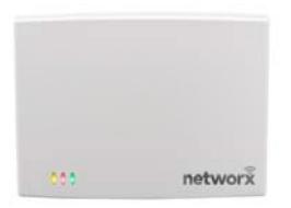
AL-IM2-80211 AL-IME2 AL-IME2POE
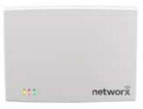
AL-IM2 SERIES WI-FI Gateway Modules
A Networx series door lock contains a radio that transmits and receives data--via a private wireless signal--to an intermediate device called a Gateway module. This Gateway module is connected (either wirelessly or wired) to a computer network such as a LAN or corporate Intranet. A Windows PC connected to this network can control and program all Networx series door locks by the use of the DL-Windows software (see OI382 and OI383). With access rights to the software, one computer--or several--can control the software and consequently can control the devices in the system. Note: See "VERSION 2", below. Several models are available:
- "Wireless / Wired" AL-IM2-80211 Hardwired / Wireless Gateway. Supplied with its own class 2 transformer to supply power and supports connection to a network either using 802.11 or a standard Ethernet cable. This "Wireless / Wired" Gateway module has two antennas, one for the proprietary radio connection to the Networx series door lock and the other for 802.11 network transmissions. Ensure adequate 802.11 coverage in the area where this Gateway is mounted. Supports up to 63 Networx locks. Ceiling- or wall-mountable.
- "Wired" AL-IME2 Hardwired Gateway, supports up to 63 Networx Locks, connects directly to a network using a standard RJ-45 Ethernet cable. This model has one antenna used to transmit to the Networx series door lock via an Alarm Lock proprietary radio connection. Ceiling- or wall-mountable. Powered with Class 2, 6VAC transformer (supplied).
- "Power over Ethernet" AL-IME2POE Hardwired Gateway + POE (Power Over Ethernet), supports up to 63 Networx Locks, connects directly to a network using a standard RJ-45 Ethernet cable and POE. This model has one antenna used to transmit to the Networx series door lock via an Alarm Lock proprietary radio connection. Ceiling- or wall-mountable.
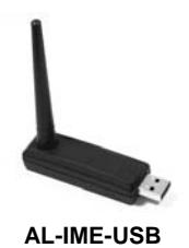
- AL-IME-USB USB Portable Gateway, virtually the same functionality of the Gateways listed above, however this highly portable and compact module connects to a standard USB 2.0 socket or greater in your Windows laptop or PC, quickly and effortlessly creating a wireless connection to your Networx series door locks. Requires DL-Windows v5.2.3 or higher. Note: Only "Local" Emergency Commands are supported when using an AL-IME-USB Gateway.
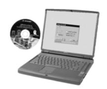
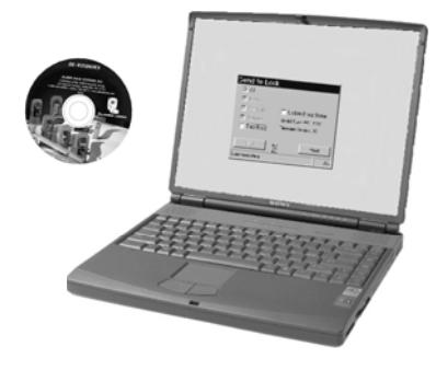
DL-Windows Software Application
Alarm Lock Trilogy Microsoft Windows-based software application, v4.0 or higher, supports Trilogy Networx and Trilogy stand alone locks, with single database (PL6100 series door locks require v5.2.3 or higher). For use with Free of charge and downloadable online at www.alarmlock.com . DL-Windows software is the basis for the wireless lock programming interface. For those unfamiliar with using DL-Windows, stop here and review the DL-Windows User's Guide, OI382 and the DL-Windows for Networx User's Guide, OI383.
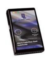
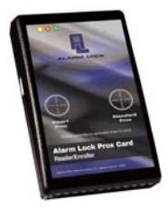
Proximity Credential Reader/Enroller ( AL-PRE2 )
An AL-PRE2 is used to quickly enroll multiple proximity credentials into DL-Windows. Use the supplied USB A to B cable to connect the AL-PRE2 to your PC running DL-Windows (V5.4.2 or higher required). Compatible with most proximity credentials (37 bits or less). Credentials are enrolled by being presented to its applicable target area on the face of the unit (see OI393).
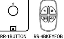
RR-1BUTTON and RR-4BKEYFOB
All Networx series door locks (including the PL6100) are compatible with the RR-1BUTTON Wireless Remote Release Button (see WI1999) and the RR-4BKEYFOB Wireless Remote Release Keyfob (see WI2004). Each requires one battery (service life of up to 12,000 openings). During normal operation, the lock typically opens within 2 seconds of the button press.

CARD®
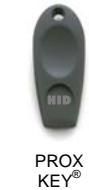
ProxCard® / ProxKey® Keyfob
Compatible with most proximity credentials, including HID ProxCards ® and ProxKey ® keyfobs (37 bits or less). Note: ProxCard® and ProxKey® are trademarks of the HID© Corporation.
Supported Products and Applications (cont'd)
AL-IM2-EXP
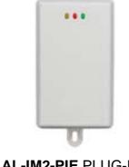
AL-IME2-PIE
The Networx™ AL-IME2-EXP Expanders extend the coverage area of AL-IME2 series Gateways, allowing control of up to its rated maximum of 63 Networx locks per Gateway. Installation is simple, as Expanders only require a connection to 12VDC power supply. AL-IME2-EXP Expanders are cost-effective, easier to wire than conventional Gateways, and feature a simplified 'Plug and Play' setup where the Networx system automatically identifies all newly powered Expanders and quickly determines the best wireless signal pathways. Up to 7 Expanders can be added to one AL-IME2 series Gateway. The easy to install AL-IME2-PIE Plug-In Expander can simply be powered by any ordinary 120VAC wall outlet. See OI391 for more information.
SITE SURVEY TOOLS
The AL-NSM Networx Signal Meter and the AL-NSG Networx Signal Generator greatly assist with identifying optimal Gateway locations for the anticipated installation doors. See WI2092 for complete information, but a general description follows:
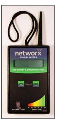
AL-NSM Networx Signal Meter
Performs a site survey test of the premises to:
- find the optimum location for Gateways relative to locks
- find the optimum location for locks relative to Gateways
- determine the optimum number of Gateways required to cover the signal area of the locks you plan to install
- perform diagnostic testing of existing Gateway radio signals within your installation environment
Using the various available Modes, the AL-NSM can measure radio noise levels, calculate overall signal quality, discover Networx locks not yet assigned to Gateways, and even send a "locate" signal (causing all unassigned locks to "beep").
The AL-NSM can be used with an existing Gateway and the "Gateway Signal Test Mode" feature in DL-Windows, or with the AL-NSG Networx Signal Generator explained below. Note: See the "Gateway Signal Test Mode" feature in the DL-WINDOWS for Networx V5 User's Guide (OI383).
AL-NSM Signal Meter
AL-NSG Signal Generator
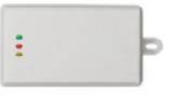
AL-NSG Networx Signal Generator
As mentioned above, the AL-NSM Signal Meter may be used with either an existing operational Gateway or the portable AL-NSG Networx Signal Generator . The AL-NSG is a portable battery-powered Gateway simulation device that generates continuous Gateway radio signals to an AL-NSM .
Depending on how you use the AL-NSG , the AL-NSG can be placed in the proposed location for a Gateway or in the proposed location of a lock, to determine the acceptability and the dependability of the radio signal coverage. The AL-NSG can be mounted using the inert nylon lanyard or reusable adhesive mounting putty (supplied with the AL-NSG ).
"VERSION 2" CONSIDERATIONS
- Before adding any of the current wireless Expander models ( AL-IME2-EXP and AL-IME2-PIE ) at least one version 2 Gateway ( AL-IM2-80211 , AL-IME2 and AL-IME2POE ) must be installed and operational in your system. The new wireless Expanders cannot communicate with any of the older Gateways ( AL-IME , AL-IM80211 , AL-IMEPOEP and AL-IME-USB ).
- Version 2 Gateways and Expanders require DL-Windows version 5.4.2 or later.
- Mixing older Gateways with Version 2 Gateways is supported by DL-Windows 5.4.2 or later.
- Compared with the original "version 1" Gateways, the "Version 2" Gateways have a different enclosure design, the operation and colors of the LEDs are different, and the location of the hidden Ethernet socket is through the rear mounting plate.
Note: The AL-IME2-POE Gateway is compatible with Alarm Lock and Continental Access products. Refer to the documentation supplied with your software for integration details.
Lock Design Overview
Why Use Proximity Cards and Fobs?
With ordinary door locks, the need to make physical copies of metal keys and distributing them can be a huge organizational and financial task -- and what will you do if someone causes a security breach by losing their key?
The answer lies in the advantage of "firmware". Firmware exists inside your Alarm Lock™ series lock, and can be changed ("programmed") to suit your changing requirements. No more metal keys to distribute...instead, distribute a proximity card or fob (for example ProxCards ® or ProxKey ® keyfobs). Lost cards or fobs can quickly and easily be deleted from the lock firmware. (Proximity cards and fobs are the firmware equivalent of metal keys; just present a valid card to the reader to unlock the PL6100). Furthermore, proximity cards and fobs differ from metal keys in that they are not duplicates ---each card is "unique" to the lock, and therefore can easily be deleted from the lock firmware without needing to be "in hand". One additional advantage is that proximity cards and fobs cannot be duplicated, unlike ordinary metal keys.
Preparing to Program your Lock
As the PL6100 does not feature keypad buttons on its housing, programming your PL6100 (for example adding or deleting proximity cards) is allowed only using a PC that is running the computer software application DL-Windows. The PC must be connected to a computer network to allow the Gateway module to wirelessly communicate with the lock's internal radio (see the Wireless Network Setup & DL-Windows Configuration Instructions, OI383 for more information about Gateway modules). DL-Windows can always be used as a back-up, restoring the information to your PL6100 lock should the future need arise.
Once you unpack your PL6100 from the box, there is a specific procedure that must be followed for proper operation (detailed in " First Time Power Up " on page 9). But first, turn the page and learn about the special terminology used with your lock. Once that is clear, use the " First Time Power Up " procedure on page 9 to help you get up and running.
Terminology Used in this Manual
Before reading this section, you may wish to first read the " Lock Design Overview " on page 6 for the basics. For a description of all features, see the DL-Windows User's Guide, OI382 or the DL-Windows for Networx User's Guide, OI383.
What is a Lock Program ?
A Lock Program contains the instructions that a lock uses to perform its various functions. Use DL-Windows (defined below) to create a Lock Program on your computer, and then transfer and store the Lock Program in the circuitry (firmware) contained inside the lock itself. The Lock Program is essentially a computer database file that maintains feature settings, proximity card data, schedules, audit trails, etc. Using DL-Windows, Lock Programs (called a "Lock Profile" in DL-Windows) can be created with default information, edited on your PC, and then sent to (or received from) locks.
The Lock Program consists of 4 areas: Prox Card Entries , Features , Time Zones , and Schedules , all defined below:
What are Prox Card Entries ?
Because this lock does not have a keypad, proximity cards and/or fobs can be added to the Lock Program to allow entry (to allow the PL6100 to unlock). The proximity card entries are a part of the Lock Program, and the Lock Program is stored in the lock circuitry (firmware) awaiting the Users to present their programmed proximity cards.
What are Features ?
Your lock is designed to support many options and functions. Using DL-Windows software (the Programmable Features window), you can select the features you wish to activate, such as if the lock will automatically adjust for Daylight Saving Time in the spring and autumn, or if the lock sounder should be disabled or enabled. Note: Features may only be added via DL-Windows
What are Schedules and TimeZones?
You can use DL-Windows to add simple "Schedules" to your lock. Schedules are events (recorded lock activities) that are assigned to occur automatically at specific times. For example, you can program the lock to allow certain Users access ONLY on Wednesdays.
DL-Windows multiplies your flexibility, allowing the creation of many different combinations of Scheduled events to suit the needs of your various installations. For example, you can program the lock to allow Group 1 Users access ONLY during specific business hours (unlock at 9AM, lock at noon for lunch, unlock at 1PM, and lock again at 5PM--every weekday).
In addition, DL-Windows makes Schedule creation much easier. In DL-Windows, use the " Schedule - TimeZone " screen to first create an individual block of time called a "TimeZone" (for example, "9AM to noon weekdays"). A TimeZone is then linked to an event to make a Schedule
(for example, "unlock between 9AM and noon weekdays"). To make Scheduling easier, DL-Windows allows TimeZones to be created, named and saved for the future, to be easily assigned to different events and added to multiple locks as needed. For more details, see the DL-Windows User's Guide, OI382 or the DL-Windows for Networx User's Guide, OI383.
What is a User ?
A User is a person who is authorized to operate or make certain programming changes to the lock. This User can be anyone--from a one-time visitor in possession of a temporary proximity card (who will almost certainly have no authority to make changes) to the owner of the building in which the lock is installed (who will almost certainly wish to have authority to make programming changes). The PL Series locks can hold up to 5000 "basic" Users in its programming memory, that means you can have up to 5000 Users each in possession of a proximity card or fob.
What is a Programming Level ?
With other Trilogy locks that possess keypads (such as the PDL3000, ETPDL, etc.), the Programming Level defines the range of programming tasks a User is allowed to perform using the keypad. However, the PL6100 lock does not include a keypad, and changes to the PL6100 Lock Program are initiated only with DL-Windows. Therefore, access to the DL-Windows computer program, with a valid password, is the sole means for determining who can make changes to the Lock Program. The DL-Windows program and its access passwords must be safeguarded, as it is essential to the security of the lock.
What is a User Number ?
( User Number = Location Number = User Location = "Slot" in Lock )
User Numbers are used primarily with DL-Windows, and are significant within each individual lock only. PL Series locks can hold up to 5000 proximity cards in its programming memory, and these cards can be thought of as simply a numbered list from 1 through 5000. Each entry in the list is represented by a User Number, and proximity card data is assigned to ("programmed into") each "location" or "slot" in this list. When a proximity card is assigned to a location, the card information is stored within the Lock Program (firmware). Because Users are physically given proximity cards, it is convenient to think of each "location" as a "User", although technically the User Number is only a location within the Lock Program. In other words, it is easier to say "User 519" rather than " The User in possession of the proximity card that is assigned to the User Location number 519 ".
Note: Where a User is located in this list--their User Location --is a commonly used description of their User Number. Because of their similarities, a User Number , User Location and Location Number can be used interchangeably. In some DL-Windows screens, the word "Slot" is also used. All of these terms are meant to convey the same concept.
Terminology Used in this Manual (cont'd)
With other Trilogy locks that possess keypads, the User Number defines the Programming Level for that User. Because the PL6100 does not contain a keypad, all User Numbers are "Basic Users", meaning each User is in possession of a proximity card, and that card is either enabled (allowing entry) or disabled (denying entry).
What is a Group ?
With many lock applications, it is convenient for large numbers of similar Users to be grouped together. All of these Users might share some common attribute--for example, they may all work in the same department of a facility, or may all work the same office hours. Placing Users into Groups (by assigning them to a specific range of User Numbers) allows large numbers of Users to be controlled all at once rather than individually--saving time and effort. A typical example involves enabling or disabling a Group at a certain time (assigning them to a Schedule; for example, to allow Group "1" Users access ONLY on Wednesdays).
How do the Emergency Commands work?
For use with DL/PDL/PL6100 series locks enrolled into the Trilogy Networx™ radio network, these wireless commands can be sent to locks during a crisis or other urgent situation. Proximity reader-only PL models require a 4-button keyfob (RR-4BKEYFOB) to send "Emergency Lockdown" and "Return to Normal" commands .
By default, Administrative Users (Users 2-11) are able send an Emergency Command. With the DL/PDL6100 locks (equipped with keypad buttons), any User Code can be programmed to allow the use of these Emergency Commands by simply adding that User Code to an "Emergency Users" list within DL-Windows. With the PL6100 lock (without keypad buttons), a wireless RR-4BKEYFOB Wireless Remote Release Keyfob button is programmed to send Emergency Commands (see Emergency Commands on page 14 for more information). When an enabled User Code is pressed at any DL/PDL6100 series lock keypad, first the lock unlocks, then the lock permits the use of these emergency commands to be sent to all locks in the network, as follows:
- ...press 911 to issue " Emergency Lock Down ", to indefinitely lock all doors;
- ...press 000 to issue " Emergency Passage ", to indefinitely unlock all doors;
- ...press 123 to issue " Return to Normal " returning all doors to "normal" (non-emergency) operation.
Note: 3 chirps sound after each emergency command entry. See page 14 and the DL-Windows User Guide OI383, " Emergency Commands " for more information. Note: DL-Windows does not need to be running to allow these "Emergency" commands to be initiated.
IMPORTANT: Although any 6100 series lock can be used to disseminate these commands throughout your Networx system, be aware that depending on how your Networx system is configured (for example, see the section
Understanding "Global" vs. "Local" on page 14) or if the Gateways in your system are divided into Emergency Groups, not all locks may respond to Emergency Commands (see the DL-WINDOWS for Networx V5 User's Guide , OI383 for more information.
Who are Users 297-300 ?
Proximity cards assigned to User Numbers 297, 298, 299 and 300 have special abilities, as follows:
User 297: Quick Enable User 300
The proximity card assigned to User Number 297 possesses the unique ability to enable the proximity card assigned to User Number 300. When proximity card 297 is presented to the lock, proximity card 300 is enabled for one time use, allowing passage for one time only. Once used, User 300's proximity card becomes disabled.
For example, you wish to allow one-time access to a temporary worker. Simply present proximity card 297 to the lock and give proximity card 300 to the temporary worker. Later, when the temporary worker presents proximity card 300 to the lock, the PL6100 unlocks and allows access for one time only. If later the temporary worker re-presents his proximity card 300 to the lock, access will be denied. Later, if you wish to grant the temporary worker access again, simply re-present proximity card 297 to the lock and proximity card 300 will be re-enabled (again for one time only).
User 298 and User 299: Guard Tour
A Guard Tour card is used to log the movement of a security guard as he or she makes rounds from one assigned guard tour station to the next. Presenting the User 299 proximity card provides precise verification and accountability of a guard's movement by logging the location with a time and date stamp in the Event Log ("Audit Trail").
Note: Proximity cards assigned to User 298 and User 299 are not access cards (meaning these proximity cards do NOT allow the security guard to pass through the door).
User 300: One-Time-Only Service Card
This is the One-Time Only Service User Card enabled by the proximity card assigned to User 297. See User 297: Quick Enable User 300 above.
What is DL-Windows ?
DL-Windows is a Microsoft Windows-based computer software program that allows you to program your PL6100 security lock. You MUST use DL-Windows to program your lock. With DL-Windows, you can quickly create Lock Programs (called "Lock Profiles" in DL-Windows) that allow you to add multiple ProxCards® and ProxKey® keyfobs, retrieve event logs, create Schedules and program many other features.
The benefit of DL-Windows is that it allows you to set up all lock programming in advance (on your computer), and then later send the information to the locks at your convenience. For more information, see OI382 and OI383.
Wiring
See the installation instructions for additional information.
Batteries:
Use only four 1.5 volt Alkaline size-C batteries or an Alarm Lock pre-wired battery pack assembly.
External Power:
Red / Black wires - External 7.5 VDC Power Source must be used for operation without batteries.
Remote Input:
White / White wires - Wire a normally open contact to wires (white and white). Momentarily close to allow PL6100 lock to unlock. NOTE: Remote Input is enabled from the factory.
Relay:
COM-Orange; N/O-Green; N/C-Yellow
Erase Memory Leads:
Yellow / Yellow wires - When shunted during power up, the Lock Program memory is erased (see ERASE ALL PROGRAMMING below).
First Time Power Up
When powered for the first time (or the "Erase All Programming" procedure performed) but before it is programmed by the wireless network Gateway, the PL6100 will remain unlocked, and will not lock until the first valid proximity card is presented to the lock.
- 1. Unpack the lock from its factory packaging.
- 2. For models with a replaceable battery pack, install fresh batteries with attention to the correct polarity as indicated inside the plastic battery pack housing. Do not connect the batteries yet.
- 3. With battery power disconnected, short the two white wires ( Remote Input wires) together for 10 seconds to ensure discharge of all capacitors. After 10 seconds, remove the short.
- 4. Plug in the (provided) male shunt connector into the yellow wire female connector.
- 5. With shunt connector connected, re-connect the battery pack. The lock will immediately sound 3 short beeps (if these 3 beeps are not heard, then restart at step 3).
- 6. The lock will then sound more slow beeps, 1 beep for every second it takes to clear the memory.
- 7. After 2 rapid beeps are heard and 2 green LED flashes are seen, unplug the shunt connector. The lock is ready for programming.
Battery Replacement
When a valid proximity card is presented to the lock and the batteries are weak, the lock will beep for the duration of the "Pass Time" programmed ("Pass Time" is the duration the lock remains unlocked after access is granted). For models with a replacable battery pack, use four (4) C-size 1.5 volt alkaline batteries. For models with a sealed battery pack, contact your Alarm Lock dealer for a replacement battery pack. Always replace weak batteries as soon as possible.
- 1. At the back of the lock, remove the lock housing screw and remove the cover.
- 2. Pull out the battery pack and quickly replace all 4 batteries within 1 minute. For models with the sealed battery pack, simply unplug the old battery pack and plug in the new battery pack.
- 3. If you do not hear the 3 beeps when power is re-applied, all programming and settings have been retained, and the lock is ready for use. Go to step 5.
- 4. If you do hear 3 beeps when power is re-applied, wait 15 seconds for the LED to flash red 7 times and 7 beeps will sound. Re-set the clock using DL-Windows.
- 5. Replace the back cover and tighten the screw.
Erase All Programming
Restore the "out of box" factory condition.
- 1. At the back of the lock, remove the lock housing screw and remove the cover.
- 2. Take out battery pack and remove battery power by disconnecting the battery pack plug.
- 3. With battery power disconnected, short the two white wires ( Remote Input wires) together for 10 seconds to ensure discharge of all capacitors. After 10 seconds, remove the short.
- 4. Plug in the (provided) male shunt connector into the yellow wire female connector.
- 5. With shunt connector connected, re-connect the battery pack. The lock will immediately sound 3 short beeps (if these 3 beeps are not heard, then restart at step 3).
- 6. The lock will then sound more slow beeps, 1 beep for every second it takes to clear the memory.
- 7. Lock is ready for programming after 2 rapid beeps are heard and 2 green LED flashes are seen.
Power Up--Retain Existing Programming
Use when re-applying power to a lock already in use (you wish to retain the Lock Program), such as when moving an existing lock to a new door, or when the lock must be dismantled and powered down for an extended period.
- 1. Disconnect battery pack connector.
- 2. With battery power disconnected, short the two white wires ( Remote Input wires) together for 10 seconds to ensure discharge of all capacitors.
- 3. Re-connect battery pack (lock will sound 3 short beeps). If these 3 beeps are not heard, then restart at step 1. The lock will perform several self tests; when complete, 7 beeps and LED flashes will sound. The lock is now ready for use.
Testing the Cards Entered
Verifying Proximity Card and Keyfob Access
Test by simply presenting a valid proximity card or fob to the reader in front of the lock.
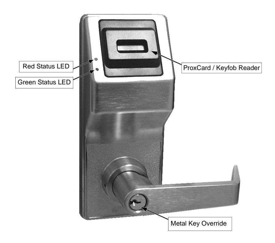
VALID CARD - Green LED flashes, the sounder beeps several times and the PL6100 unlocks.
INVALID CARD - Red LED flashes several times and the sounder beeps several times.
LED and Sounder Indicators
With a fully charged battery, the LED and sounder provide visual and audible feedback as follows:
| ACTIVITY | LED | SOUNDER | COMMENTS |
|---|---|---|---|
|
Access Granted or
Remote Release |
2 Green Flashes | 2 Beeps | Valid credential (proximity credential, Remote Input or Wireless Remote Release) |
| Invalid Card / Fob | 7 Red Flashes | 7 Beeps | An invalid proximity card / fob does not exist in the Lock Program memory. |
|
Valid but Disabled
Card / Fob |
1 Green, 4 Red Flashes | 1 Long, 5 Short Beeps | A proximity card / fob exists in the firmware, but is disabled. |
| Emergency Commands are in effect | 1 RED Flash every two seconds | ||
| Low Battery | Red LED and Sounder turn on steady for the duration of the "Pass Time". | See page 9 ("Battery Replacement") before changing batteries. ("Pass Time" is the duration the lock remains unlocked after access is granted). | |
DL-Windows Programmable Functions "Programmable Features" Screen - Options tab
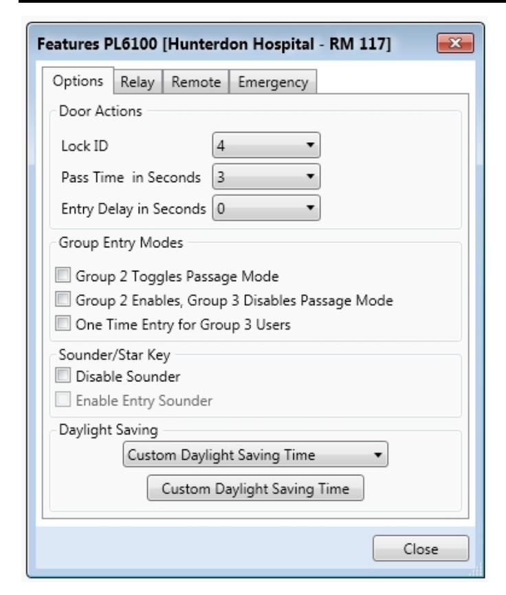
You can program the PL6100 to perform certain functions when various events occur. For a description of all features, see the DL-Windows User's Guide, OI382 or the DL-Windows for Networx User's Guide, OI383; the most common are listed below.
Lock ID
Door Number must be between 1– 2000. If the lock is a new lock without a designated LockID, the ID number specified in this field will be assigned to the programmed lock.
Pass Time In Seconds
The duration in seconds that the PL6100 will remain unlocked after a valid proximity card has been presented (valid entries are 3, 10 & 15 seconds).
Entry Delay in Seconds
Delays door entry after valid proximity card has been presented.
Group 2 Toggles Passage Mode
A Group 2 User will toggle passage mode (lock is unlocked). Caution! The consequences of accidentally selecting this option can cause a security breach!
Group 2 Enables, Group 3 Disables Passage Mode
A Group 2 User will put the PL6100 into passage mode (lock is unlocked). A Group 3 User will take the PL6100 out of passage. Caution! The consequences of accidentally selecting this option can cause a security breach!
One Time Entry for Group 3 Users
If checked, allows Group 3 Users to unlock the PL6100 one time only (thereafter their Group 3 proximity credential is disabled).
Disable Sounder
Disable the Sounder to allow for silent operation.
Enable Entry Sounder
Check to enable sounder to activate upon each Access Granted or Remote Input activation.
Daylight Saving
The lock will adjust for Daylight Saving Time. See the DL-Windows User's Guide, OI382.
DL-Windows Programmable Functions "Programmable Features" Screen - Relay Functions tab
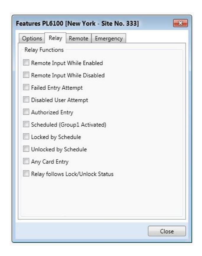
Select any of the relay functions below to activate the integral relay output (more than one may be selected).
Remote Input While Enabled
Activates relay when the Remote Input (two white wires inside the rear housing) are momentarily shorted. Provides an alert that access has been granted via the Remote Input.
Remote Input While Disabled
Activates relay when the Remote Input wires (two white wires inside the rear housing) are momentarily shorted when the Remote Input is disabled. Provides an alert that an unsuccessful access has been attempted via the Remote Input.
Failed Entry Attempt
Activates relay if any unsuccessful proximity card entry attempt occurs. Provides an alert that an unauthorized proximity card entry attempt has been detected.
Disabled User Attempt
Activates relay if a User presents their proximity card
while that proximity card is disabled. Provides an alert that a disabled proximity card entry attempt has been detected.
Authorized Entry
Activates relay anytime a User presents a valid proximity card and is granted access.
Scheduled (Group 1 Activated)
Activates relay if the PL6100 has been programmed for "Scheduled Relay Activation (Group 1 Initiated)" and a member of Group 1 has presented their proximity card within the required window.
Locked by Schedule
Activates relay if the PL6100 has been locked by a programmed schedule.
Unlocked by Schedule
Activates relay if the PL6100 has been unlocked by a programmed schedule.
Any Card Entry
Activates relay any time a proximity card is presented.
Relay follows Lock/Unlock Status
Activates relay when the PL6100 is unlocked. Relay power must be provided from an external power supply. If this option is selected, the relay remains activated as long as the PL6100 is unlocked. This feature supersedes all other relay options.
"Programmable Features" Screen - Remote tab
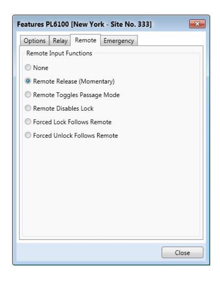
duration of Remote Input switch closure.
Important: If this feature is enabled, power to the lock MUST be provided from an external power supply.
Forced Lock Follows Remote
When Remote Input switch is closed, regardless of the current state of the lock, the lock will lock for the duration of the Remote Input switch closure.
Important: If this feature is enabled, power to the lock MUST be provided from an external power supply.
Forced Unlock Follows Remote
When Remote Input switch is closed, regardless of the current state of the lock, the lock will unlock for the duration of the Remote Input switch closure.
Important: If this feature is enabled, power to the lock MUST be provided from an external power supply.
The "Remote Input" wires are two white wires located inside the rear housing. When these two white Remote Input wires are momentarily shorted, the PL6100 unlocks. These Remote Input wires are enabled at the factory and are ready for use.
Program Remote Input Functions as follows:
Remote Release (Momentary)
Check to enable the Remote Input feature in the selected PL6100 lock. Will cause the PL6100 to unlock when the two white Remote Input wires are momentarily shorted.
Remote Toggles Passage Mode
Remote Input activation toggles Passage Mode (Passage Mode allows passage through the door without the need for a valid proximity card to be presented).
Remote Disables Lock
Regardless of the current state of the lock, that state will remain unchanged (and lock will be disabled) for the
Emergency Commands
Emergency Commands
The PL6100 series locks can be programmed to send Emergency Commands (" Emergency Lock Down " and " Return to Normal ") initiated from an RR-4BKEYFOB Wireless Remote Release Keyfob . When Global Lockdown is enabled, Emergency commands are supported, including " Emergency Passage " initiated from DL-Windows or by another Networx lock. ( Note: " Emergency Passage " is not available with the Wireless Remote Release ).
Emergency Commands are available in two types: " Global " or " Local ":
- With " Global Emergency Commands ", activating the Emergency Command changes the state of all locks in the entire system (depending on which Emergency Command settings are selected).
- With " Local Emergency Commands ", only the lock that initiates the Emergency Command will change state; activating the Emergency Command does NOT change the state of all locks in the entire system.
IMPORTANT: For more information about how Emergency Commands work with your ENTIRE system, see the DL-Windows for Networx User's Guide (OI383). Always test each lock in your system to ensure each lock operates as expected when Emergency Commands are activated .
Understanding "Global" vs. "Local"
The following features should be understood before using Emergency Commands with your PL6100. Below describes the various features available for Global Emergency Commands or Local Emergency Commands , or combinations of both.
TIP: If using an RR-4BKEYFOB Wireless Remote Release , before reading this page, we recommend that you read the documentation that came with it, and also the " Wireless Remote Releases " section on page 16.
Receiving Emergency Commands
Lock Responds to Global Emergency Commands
- When enabled: The lock WILL accept and adhere to Emergency Commands that disseminate from another lock or from DL-Windows. Note: This feature does not need to be enabled (checked) for the lock to accept commands from an RR-4BKEYFOB Wireless Remote Release .
- When disabled: The lock WILL NOT accept nor adhere to Emergency Commands that disseminate from another lock or from DL-Windows. CAU-TION: Disabling (un-checking) this feature could be of great consequence for the safe administration of your Networx system.
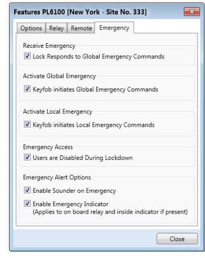
Activating Global Emergency Commands
Keypad initiates Global Emergency Commands : When enabled (checked), if an Emergency Command is initiated from the keypad, the lock will first inform the Gateway to broadcast the Emergency Command to all locks assigned to the same " Gateway Group ", then the lock will respond to that Emergency Command accordingly (if the above " Lock Responds to Global Emergency Commands " is enabled).
Keyfob initiates Global Emergency Commands : When enabled (checked), if an Emergency Command is initiated from an RR-4BKEYFOB Wireless Remote Release , the "paired" lock will first inform the Gateway to broadcast the Emergency Command to all locks assigned to the same " Gateway Group ", then the paired lock will respond to that Emergency Command accordingly (if the above " Lock Responds to Global Emergency Commands " is enabled).
Note: See OI383 for more information about Gateway Emergency Groups.
Activating Local Emergency Commands
Keypad initiates Local Emergency Commands : When enabled (checked), if an Emergency Command is initiated from the keypad, the lock will immediately change state accordingly. The Emergency Command will NOT be sent to the Gateway and therefore will NOT be sent to other locks in the system.
Keyfob initiates Local Emergency Commands : When enabled (checked), if an Emergency Command is initiated from an RR-4BKEYFOB Wireless Remote Release , the paired lock will immediately change state accordingly. The Emergency Command will NOT be sent to the Gateway and therefore will NOT be sent to other locks in the system.
Emergency Commands (cont'd)
TIP: Combining Global and Local Features: You can combine the various Global and Local Emergency features to customize your system.
Example #1: DL-Windows by default enables (checks) all of the features, as shown above in the Features dialog. What will happen when all features are enabled and an " Emergency Lock Down " command is initiated at the keypad? Because the Activate Local Emergency commands are enabled, the lock that initiates the Emergency Command will lock down, then the lock will inform the Gateway to broadcast the Emergency Command to all locks assigned to the same " Gateway Group ".
Example #2: This example is known as the "pull station option", where one of the Activate Global Emergency commands is checked, none of the Activating Local Emergency commands are checked, and the " Lock Responds to Global Emergency Commands " is unchecked. If an " Emergency Lock Down " command is initiated at a lock keypad, the lock will first inform the Gateway to broadcast the Emergency Command to all locks assigned to the same " Gateway Group ", then the lock will ignore the broadcast when received.
Emergency Users
Activating Emergency Commands
By default, Administrative Users (Users 2 through 11) automatically have the ability to initiate Emergency Commands from the keypad. In addition, "Basic Users" (Users 12+) may be granted the ability to initiate Emergency Commands from the keypad by adding them as Emergency Users in DL-Windows (for more information about adding Emergency Users in DL-Windows, see OI383). Note: All paired Wireless Remote Releases have the ability to initiate Emergency Commands (see page 16 for more information).
When a User Code from an Administrative or Emergency User is pressed at any 6100 series lock keypad, first the 6100 series lock unlocks, then the lock permits the use of the following Emergency Commands: ...press 911 to issue " Emergency Lock Down " ...press 000 to issue " Emergency Passage " ...press 123 to issue " Return to Normal " [ _ _ _ _ ] Administrative or Emergency User Code
Access During an Emergency
- When enabled: If the feature Users are Disabled During Lockdown is enabled (checked) for a specific lock, and when the Networx system is in an Emergency Lock Down state, "Basic Users" (Users 12+) are denied the ability to unlock the physical lock (User Codes / proximity credentials for these Basic Users are ignored). The User Codes / proximity credentials added to Administrative Users (Users 2 through 11) as well as all "Emergency Users" remain enabled , retaining the ability to unlock a secured lock.
- When disabled: If the feature Users are Disabled During Lockdown is disabled (unchecked) for a specific lock, and when the Networx system is in an Emergency Lock Down state, ANY valid User Code or proximity credential that exists in the lock's internal memory will be allowed to unlock the secured lock, regardless of User Number.
Emergency Alert Options
Sounder
If Enable Sounder on Emergency is enabled (checked), upon receiving an Emergency Command, the integral sounder will beep once per second for 30 seconds.
Emergency Indicator
When the feature Enable Inside Emergency Indicator is enabled (checked), upon receiving the Emergency Command, the lightbar (located on the inside housing) flashes a red LED once per second for the duration of the Emergency. For locks equipped without the lightbar, the internal relay will activate once per second.
Tip: Only "Local" Emergency Commands are supported when using an AL-IME-USB Gateway . See page 4 for Gateway model descriptions.
Wireless Remote Releases
Overview
Two types of wireless remote releases are compatible with the PL6100 : The RR-1BUTTON Wireless Remote Release Button (see WI1999) and RR-4BKEYFOB Wireless Remote Release Keyfob (see WI2004). Whether the remote release contains a single button or four, each button can be "paired" (connected) with one PL6100 series lock. For example, the four buttons on the RR-4BKEYFOB can each be paired with four separate PL6100 locks. Each individual PL6100 contains ten (10) "slots" ("User Numbers"), with each "slot" available to accommodate one paired remote release button. Therefore, each individual PL6100 can ultimately be paired with up to ten remote release buttons on multiple wireless remote release devices. Note: Since each button can ONLY be paired with one specific PL6100 lock at a time, when a previously paired button is later paired with a second locking device, the first pairing is erased.
Note: Wireless remote releases can be paired to a "stand-alone" lock before it is enrolled into a Networx system. However, to allow for this "stand-alone" lock to be discovered later, it MUST first be defaulted as per the ERASE ALL PROGRAMMING procedure on page 10, thus clearing all previously programmed Users and paired wireless remote releases .
RR-1BUTTON
RR-4BKEYFOB
Pairing Wireless Remote Release Buttons
The following pairing procedure assumes the PL6100 lock has been powered and at least one Administrative User proximity credential (Users 2-11) has been enrolled into the lock (its DL-Windows Lock Profile downloaded into the lock). Keep this proximity credential physically available, as it will be used during the below procedure. Note: The following procedure is unique to the PL6100 and is NOT supplied with the programming instructions included with the remote release ( RR-1BUTTON , WI1999 and RR-4BKEYFOB , WI2004). Proceed as follows:
- 1. Disconnect the lock battery connector.
- 2. Short the two white wires (Remote Input wires) together for 10 seconds to ensure discharge of all capacitors. After 10 seconds, remove the short.
- 3. Re-connect the battery pack. The lock immediately sounds 3 short beeps (if these 3 beeps are not heard, start again at step 1). Over the next 7 - 9 seconds, the lock performs its power-up self-test, and indicates it is ready to operate by sounding 7-beeps.
- 4. At the lock proximity reader, present the enrolled Administrative User (Users 2-11) proximity card. The lock unlocks and enters a 30-second "remote release enroll sequence" during which the green LED flashes.
-
5. With the remote release in hand, observe the remote release LED as you perform the next steps:
- a. Press and hold a remote release button.
- b. The remote release red LED lights...keep holding the button…
- c. When the remote release LED flashes green, release the button...
- d. Wait a few seconds...observe the LED as follows:
- LED solid green = Pairing successful. To pair another button, go to step 1.
- LED solid red = Pairing unsuccessful. Start again at step 1.
After step 5, the lock will exit the "remote release enroll sequence" and will return to normal operation.
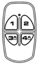
Emergency Lock Down (via Wireless Remote Release) The PL6100 series lock has the added ability to accept Emergency Lock Down commands from a Wireless Remote Release (model RR-4BKEYFOB only). Using the RR-4BKEYFOB, when buttons 3 and 4 are pressed simultaneously, within seconds an Emergency Lock Down command is sent to all locks to which the RR-4BKEYFOB is currently paired (up to 4). Conversely, pressing buttons 1 and 2 simultaneously will send a Return to Normal command, returning the paired locks back to the state they were in prior to receiving the Emergency Lock Down command.
See page 14 for the two different modes (see the section "Global" vs. "Local" ) to which the PL6100 series lock will respond when an Emergency Command when sent from a Wireless Remote Release.
User Card Record Sheet
| Page # |
|---|
| NAME OF DOOR: | DEPARTMENT: |
|---|---|
| EMBOSSED NUMBER ON CARD | USER NAME (LAST, FIRST) | DATE ACTIVATED | COMMENTS |
|---|---|---|---|
User Card Record Sheet
| Page # |
|---|
| NAME OF DOOR: | DEPARTMENT: |
|---|---|
| EMBOSSED NUMBER ON CARD | USER NAME (LAST, FIRST) | DATE ACTIVATED | COMMENTS |
|---|---|---|---|
Glossary
ACCESS = Entry into a restricted area.
AUDIT TRAIL = A date/time stamped log of previous lock events.
BURGLARY CONTROL PANEL = Provides local alarm and remote communication to request security for burglary/break-in.
CLOCK
- REAL TIME CLOCK = An accurate built-in clock that allows date/time stamping of events. The clock can be slowed or speeded up to fine tune long term accuracy to within three minutes per year. Programmed only through DL-Windows.
- CLOCK SETTINGS = Printout includes date, time, weekday, and clock speed.
- DATE = Month, Day and Year entered as MMDDYY. Programmed only through DL-Windows.
- DAY OF WEEK = Sunday through Saturday (where 1 = Sunday and 7 = Saturday). Programmed only through DL-Windows.
- DEFAULT = The original settings that were set at the factory; in other words, it is the lock's original factory condition when the lock was first taken out of its box. The default settings are permanently encoded within the lock's fixed memory, and when the lock is first started, or when power is removed and re-applied (see pages 9-10), the original factory default settings are re-loaded and take effect.
DISABLE = Turn off.
DOWNLOAD = Send data to lock.
ENABLE = Turn on.
EVENTS = Recorded lock activity.
GROUP
- USER GROUP = Defining a User to specific Groups, allows User entry when the Group is allowed entry. Programmed only through DL-Windows.
- GROUP 1 DISARMS BURGLAR CONTROL = A proximity card (previously assigned to Group 1) presented to the lock can disarm an alarm control panel during a predefined scheduled time (if the proximity card is used outside of the scheduled time, the alarm control panel will not disarm). The alarm control panel must be armed through other means, must be programmed to disarm from an armed state only, and the zone input must be programmed for input disarming. Programmed only through DL-Windows.
- GROUP 1 ENABLES GROUP 4 USERS = A proximity card (previously assigned to Group 1) presented to the lock during a predefined schedule allows access to Group 4 Users. Programmed only through DL-Windows.
- GROUP 1 PUTS UNIT IN PASSAGE = A proximity card (previously assigned to Group 1) pre-
- sented to the lock during a pre-defined schedule unlocks the lock. Programmed only through DL-Windows.
- ONE TIME ONLY FOR GROUP 3 USERS = If selected in DL-Windows, allows Group 3 proximity cards to unlock the door one time only (thereafter their proximity card becomes disabled). See OI382.
- GUARD TOUR = Associated with User 298 and User 299. A Guard Tour card is used to log the movement of a security guard as he or she makes rounds from one assigned guard tour station to the next. Presenting the User 299 proximity card provides precise verification and accountability of a guard's movement by logging the location with a time and date stamp in the Event Log ("Audit Trail"). Note: Proximity cards assigned to User 298 and User 299 are not access cards (meaning these proximity cards do NOT allow the security guard to pass through the protected door).
- INTERNAL RELAY FUNCTIONS = The PL6100 internal relay can be programmed (via DL-Windows only) for one or more functions. See page 12 for more information.
LOG = See... AUDIT TRAIL.
- PASSAGE = Allow anyone to pass through the door without proximity cards or fob ("door is unlocked").
- RELAY = Switched output allowing remote control of other devices.
- REMOTE INPUT = Allows entry into a restricted area by pressing a button connected to the two RE-MOTE INPUT wires (two internal white wires) by someone on the protected side of the door.
- SCHEDULE = A programmed operation (enable/ disable, lock/unlock, etc.) on a specific day (Sunday through Saturday) and time. Programmed only through DL-Windows.
- SCHEDULES, QUICK = Any one of four most common types of schedules can be programmed. Programmed only through DL-Windows.
- TIME = Hours and Minutes in the HHMM format. Programmed only through DL-Windows.
- TIME / DATE STAMP = A recorded date and time that an event occurred.
- TIMEOUT = Allowing or restricting operation for a specified number of hours.
UPLOAD = Receive data from the lock.
- USER = A person who has been provided with a proximity USER CARD for access through the door.
- USER LOCKOUT, TOTAL = All Users to be locked out (denied access). Proximity User Cards will not unlock the PL6100.
ALARM LOCK LIMITED WARRANTY
ALARM LOCK SYSTEMS, INC. (ALARM LOCK) warrants its products to be free from manufacturing defects in materials and workmanship for twenty four months following the date of manufacture. ALARM LOCK will, within said period, at its option, repair or replace any product failing to operate correctly without charge to the original purchaser or user.
This warranty shall not apply to any equipment, or any part thereof, which has been repaired by others, improperly installed, improperly used, abused, altered, damaged, subjected to acts of God, or on which any serial numbers have been altered, defaced or removed. Seller will not be responsible for any dismantling or reinstallation charges, environmental wear and tear, normal maintenance expenses, or shipping and freight expenses required to return products to ALARM LOCK. Additionally, this warranty shall not cover scratches, abrasions or deterioration due to the use of paints, solvents or other chemicals.
THERE ARE NO WARRANTIES, EXPRESS OR IM-PLIED, WHICH EXTEND BEYOND THE DESCRIPTION ON THE FACE HEREOF. THERE IS NO EXPRESS OR IMPLIED WARRANTY OF MERCHANTABILITY OR A WARRANTY OF FITNESS FOR A PARTICULAR PUR-POSE. ADDITIONALLY, THIS WARRANTY IS IN LIEU OF ALL OTHER OBLIGATIONS OR LIABILITIES ON THE PART OF ALARM LOCK.
Any action for breach of warranty, including but not limited to any implied warranty of merchantability, must be brought within the six months following the end of the warranty period.
IN NO CASE SHALL ALARM LOCK BE LIABLE TO ANY-ONE FOR ANY CONSEQUENTIAL OR INCIDENTAL DAMAGES FOR BREACH OF THIS OR ANY OTHER WARRANTY, EXPRESS OR IMPLIED, EVEN IF THE LOSS OR DAMAGE IS CAUSED BY THE SELLER'S OWN NEGLIGENCE OR FAULT.
In case of defect, contact the security professional who installed and maintains your security system. In order to exercise the warranty, the product must be returned by the security professional, shipping costs prepaid and insured to ALARM LOCK. After repair or replacement, ALARM LOCK assumes the cost of returning products under warranty. ALARM LOCK shall have no obligation under this warranty, or otherwise, if the product has been repaired by others, improperly installed, improperly used, abused, altered, damaged, subjected to accident, nuisance, flood, fire or acts of God, or on which any serial numbers have been altered, defaced or removed. ALARM LOCK will not be responsible for any dismantling, reassembly or reinstallation charges, environmental wear and tear, normal maintenance expenses, or shipping and freight expenses required to return products to ALARM LOCK. Additionally, this warranty shall not cover scratches, abrasions or deterioration due to the use of paints, solvents or other chemicals.
This warranty contains the entire warranty. It is the sole warranty and any prior agreements or representations, whether oral or written, are either merged herein or are expressly cancelled. ALARM LOCK neither assumes, nor authorizes any other person purporting to act on its behalf to modify, to change, or to assume for it, any other warranty or liability concerning its products.
In no event shall ALARM LOCK be liable for an amount in excess of ALARM LOCK's original selling price of the product, for any loss or damage, whether direct, indirect, incidental, consequential, or otherwise arising out of any failure of the product. Seller's warranty, as hereinabove set forth, shall not be enlarged, diminished or affected by and no obligation or liability shall arise or grow out of Seller's rendering of technical advice or service in connection with Buyer's order of the goods furnished hereunder.
ALARM LOCK RECOMMENDS THAT THE ENTIRE SYS-TEM BE COMPLETELY TESTED WEEKLY.
Warning: Despite frequent testing, and due to, but not limited to, any or all of the following; criminal tampering, electrical or communications disruption, it is possible for the system to fail to perform as expected. ALARM LOCK does not represent that the product/system may not be compromised or circumvented; or that the product or system will prevent any personal injury or property loss by burglary, robbery, fire or otherwise; nor that the product or system will in all cases provide adequate warning or protection. A properly installed and maintained alarm may only reduce risk of burglary, robbery, fire or otherwise but it is not insurance or a guarantee that these events will not occur. CONSEQUENTLY, SELLER SHALL HAVE NO LIA-BILITY FOR ANY PERSONAL INJURY, PROPERTY DAMAGE, OR OTHER LOSS BASED ON A CLAIM THE PRODUCT FAILED TO GIVE WARNING. Therefore, the installer should in turn advise the consumer to take any and all precautions for his or her safety including, but not limited to, fleeing the premises and calling police or fire department, in order to mitigate the possibilities of harm and/or damage.
ALARM LOCK is not an insurer of either the property or safety of the user's family or employees, and limits its liability for any loss or damage including incidental or consequential damages to ALARM LOCK's original selling price of the product regardless of the cause of such loss or damage.
Some states do not allow limitations on how long an implied warranty lasts or do not allow the exclusion or limitation of incidental or consequential damages, or differentiate in their treatment of limitations of liability for ordinary or gross negligence, so the above limitations or exclusions may not apply to you. This Warranty gives you specific legal rights and you may also have other rights which vary from state to state.