Alarm Lock PG10 Installation Instructions
Open the original PDF document
View PDFInstallation and Operating Instructions
Model PG-10
PILFERGUARD
Installation
- 1. To Remove Cover: Depress test button and lift cover out of slot.
- 2. Mark and drill holes as per template directions and drill sizes. (5 for alarm unit, 2 for magnetic actuator).
-
3. For outside cylinder installation where required (go to step 4 if not).
- A. Drill a 1¼" hole as shown on template.
- B. Install a rim type cylinder through the door and allow flat tailpiece to extend 1" inside door.
- C. Position cylinder so that keyway is vertical (horizontal if PG-10 is installed horizontally).
- D. Hold PG-10 in position over mounting holes and note that outside cylinder tailpiece is centered in clearance hole in base of PG-10 (rotate cylinder 180° if not).
- E. Tighten outside cylinder mounting screws.
- 4. Install PG-10 and magnetic actuator with 7 screws.
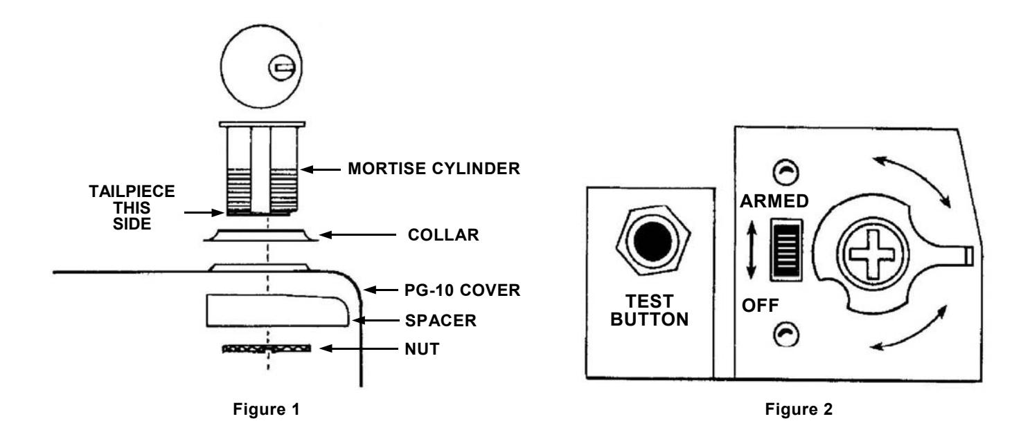
- 5. Install threaded (mortise) cylinder (1¼" long) in PG-10 cover using hardware supplied (see Figure 1). Key way must be horizontal so that tailpiece extends towards center of unit when key is turned.
- 6. Move slide switch to "OFF" (see Figure 2).
Connect battery.
Hook cover on end slot and secure with two cover screws.
Note: One of these screws acts as tamper alarm trigger, so be sure screws are fully seated. This completes the installation, proceed to "check-out".

Check-Out and Operation
- 1. With slide switch in "OFF" position, depress test button horns should sound.
-
2. To test using magnetic actuator:
- A. Close Door.
- B. Arm PG-10 by turning key clockwise 170 degrees.
- C. Open door, alarm should sound.
- D. Close door, alarm should remain sounding.
- E. Silence alarm by turning key counterclockwise until it stops.
- 3. Close door and re-arm PG-10 by turning key clockwise until it stops.
- 4. Periodic Test: Unit should be tested weekly using test button to ensure battery is operational. Note: Test button only operates when PG-10 is turned off.
Special Conditions
Steel Frames - It is sometimes necessary on steel frames to install a non-magnetic shim between the magnetic actuator and the frame. This is done to prevent the steel frame from absorbing the magnets' magnetic field, which could cause a constant alarm condition or occasional false alarms.
The shim should be " by " by " thick and may be constructed from plastic, bakelite or aluminum.