Alarm Lock Model 250WP 260WP (Waterproof) Installation Instructions
Open the original PDF document
View PDFOPERATING INSTRUCTIONS
BEFORE INSTALLING THE LOCK COVER:
-
1) Select:
- For continuous alarm , leave the black jumper plug on the terminal strip, as installed.
- For two minute auto-alarm shutdown , remove the black jumper plug from the terminal strip.
- 2) Connect the battery connector to the 9-volt battery observing the proper polarity. A short beep will sound ensuring that the lock is powered and ready.
- 3) Install the lock cover with four (4) screws supplied.
- 4) Close the door.
OPERATIONAL TESTING
- 1) Lock and unlock the door using the cylinder key and note a small beep will sound when the deadbolt is retracted, indicating a disarmed condition. The door can now be opened without an alarm, by pushing the clapper plate.
-
2) Lock the door again and push the clapper plate to open it. Immediately the alarm will pulse loudly and one of the following will occur:
- A) If continuous alarm has previously been selected the alarm will sound until the lock is manually reset by locking the deadbolt with the key.
- B) If auto-alarm shutdown has been selected, the alarm will sound for two minutes then reset.
LOW BATTERY DETECTION
When the battery becomes weak, the sounder will emit a short beep approximately once a minute indicating the battery needs replacing.
RETRIGGERABLE OPERATION
If the unit has a retriggerable alarm (Model 260), after the initial two minute alarm and auto shutdown, the alarm will retrigger if the door is opened again. This function will remain retriggerable until the door is relocked with the key. NOTE: Whenever an alarm is caused by opening the door, and the door is left open, the two minute alarm shutdown will be inhibited.
ALARM LOCK LIMITED WARRANTY
ALARM LOCK SYSTEMS, INC. warrants each of its products to be free from manufacturing defects in materials and workmanship for fifteen months following the date of manufacture. ALARM LOCK will, within said period, at its option, repair or replace any product failing to operate correctly, without charge to the original purchaser or user.
This warranty shall not apply to any equipment or any part thereof which has been repaired by others, improperly installed, improperly used, abused, altered, damaged, subjected to accident, nuisance, flood, fire or acts of God, or on which any serial numbers have been altered, defaced or removed. Seller will not be responsible for any dismantling, reassembly or reinstallation charges.
In order to exercise the warranty, the product must be returned by the user or purchaser, shipping costs prepaid, and insured to ALARM LOCK. After repair or replacement, ALARM LOCK assumes the cost of returning products under warranty.
There are no warranties, express or implied which extend beyond the description on the face hereof. There is no express or implied warranty of merchantability or a warranty of fitness for a particular purpose. Additionally, this warranty is in lieu of all other obligations or liabilities on the part of ALARM LOCK.
This warranty contains the entire warranty. It is the sole warranty and any prior agreements, or, representations, whether oral or written, are either merged herein or are expressly cancelled. ALARM LOCK neither assumes, nor authorizes any other person purporting to act on its behalf to modify, to change, nor to assume for it, any other warranty or liability concerning its products.
In no event shall ALARM LOCK be liable for an amount in excess of ALARM LOCK's original selling price of the product, for any commercial loss or damage, whether direct, indirect, incidental, consequential, or otherwise arising out of any failure of the product. Seller's warranty, as hereinabove set forth, shall not be enlarged, diminished or affected by and no obligation or liability shall arise or grow out of Seller's rendering of technical advice or service in connection with Buyer's order of the goods furnished hereunder.
Warning: Despite, frequent testing, and due to, but not limited to, any or all of the following; criminal tampering, electrical or communications disruption, it is possible for the system to fail to perform as expected. Therefore, the consumer is advised to take any and all precautions for his or her safety including, but not limited to, fleeing the premises and calling police or fire department, in order to mitigate the possibilities of harm and/or damage.
This warranty shall be construed in accordance with the laws of the State of New Jersey.
WI1862 02/10
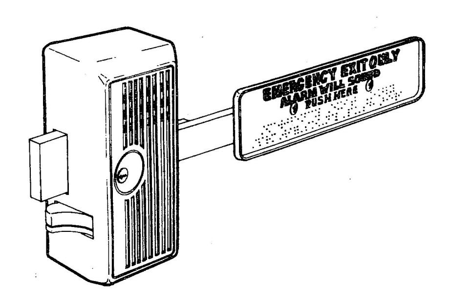
INSTALLATION & OPERATING INSTRUCTIONS WATERPROOF ELECTRONIC PANIC LOCKS 250 SERIES MODELS

ALARM LOCK SYSTEMS, INC. 345 BAYVIEW AVE., AMITYVILLE, NY 11701
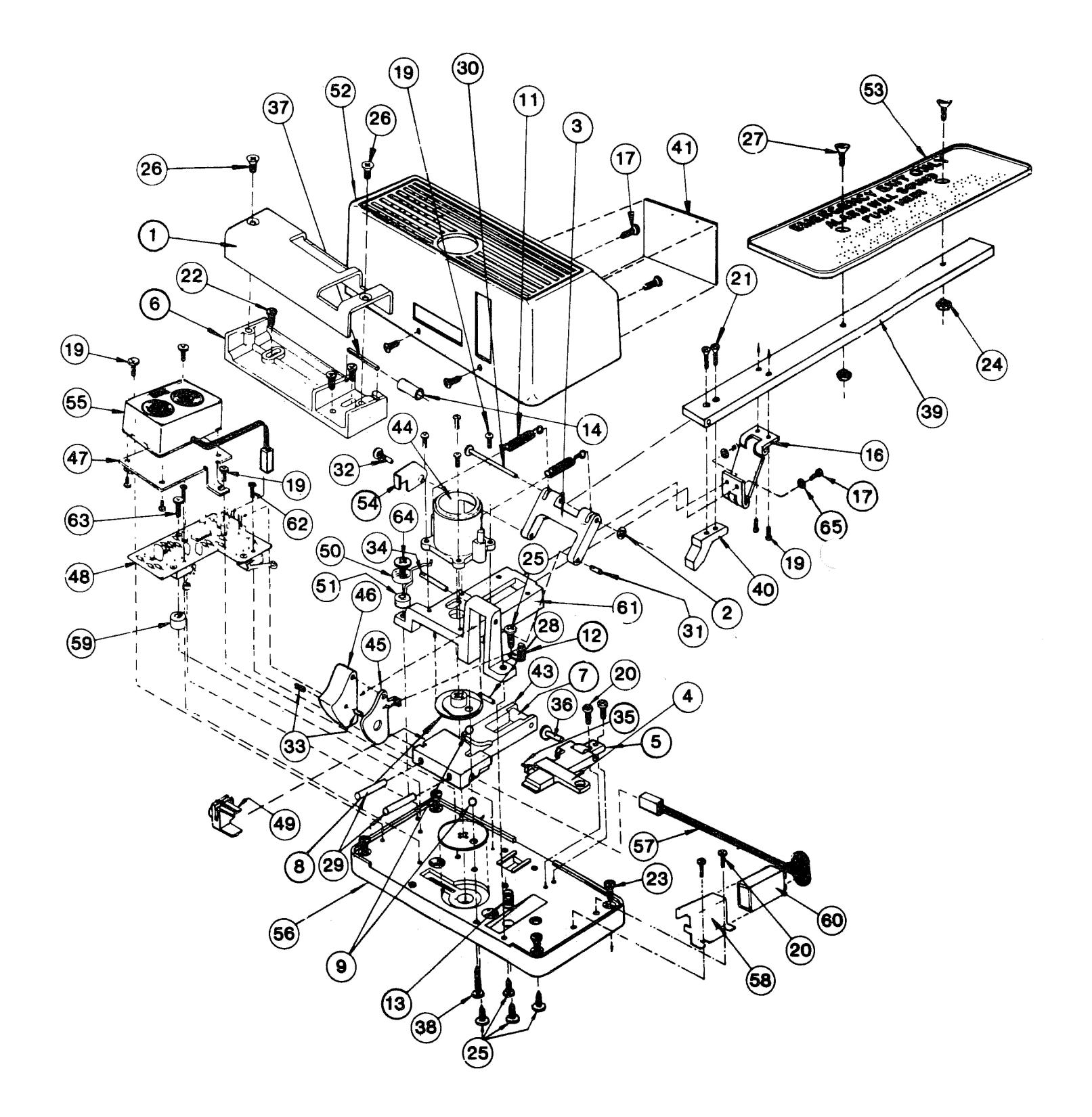
DETAIL ASSEMBLY 250 SERIES
| DES |
. '
P' N O. |
DES
CR ION IPT |
DES |
'P'
NO |
DES
CR ION IPT |
|---|---|---|---|---|---|
| 1 |
P02
48 |
KEE
PER CO VER |
33 |
P19
32 |
(
SS'Y ) PAR T O F S 525 2 A |
| 2 |
P11
40 |
(
SS'Y ) PAR T O F S 525 1 A |
34 |
P19
33 |
(
SS'Y ) PAR T O F S 525 2 A |
| 3 |
P11
46 |
(
SS'Y ) PAR T O F S 525 2 A |
35 |
P19
34 |
(
S'Y) PAR T O F S3 120 AS |
| 4 |
P11
51 |
(
PAR T O F S3 120 AS S'Y) |
36 |
P19
35 |
(
PAR T O F S3 120 AS S'Y) |
| 5 |
P11
52 |
(
T O F S3 120 AS S'Y) PAR |
37 |
P19
37 |
(
T O F S3 121 AS S'Y) PAR |
| 6 |
P11
57 |
SE
KEE PER BA |
38 |
P41
55 |
10-
24 X 5/ 8 P H P HIL |
| 7 |
58
P11 |
(
T O F S3 113 AS S'Y) PAR |
39 |
P44
93 |
CLA
PPE R A RM |
| 8 |
P11
59 |
(
S'Y) PAR T O F S3 114 AS |
40 |
P44
95 |
TRI
GG ER CAM |
| 9 |
P11
60 |
(
PAR T O F S3 114 AS S'Y) |
41 |
P52
32 |
PRO
D-L ABE L 25 0/ 260 |
| 10 |
P02
50 |
KEE
PER CO VER * |
42 |
P51
11 |
LOC
K C OVE R ( DUR ON OD IC) * |
| 11 |
68
P11 |
(
T O F S 525 2 A SS'Y ) PAR |
43 |
43
P11 |
(
T O F S3 113 AS S'Y) PAR |
| 12 |
69
P11 |
CH
P S NG LAT TRI PRI |
44 |
P11
45 |
(
T O F S 525 2 A SS'Y ) PAR |
| 13 |
P11
70 |
D'LO
CK LEV ER SPR ING |
45 |
P11
49 |
(
SS'Y ) PAR T O F S 525 2 A |
| 14 |
P11
71 |
(
S'Y) PAR T O F S3 121 AS |
46 |
P11
50 |
(
SS'Y ) PAR T O F S 525 2 A |
| 15 |
P12
50 |
CLA
PPE R P LAT E ( LON G) * |
47 |
P50
12 |
PIE
ZO MT . PL ATE |
| 16 |
P12
60 |
HIN
GE |
48 |
S52
27 |
SUB
-AS S'Y PCB |
| 17 |
08
P15 |
6-3
2 X 1/ SS 4 L TRU HD |
49 |
P50
19 |
CAM
FO LLO WE R |
| 18 |
P45
45 |
CLA
PPE R A RM |
50 |
P50
29 |
SIO
N S NG TEN PRI |
| 19 |
P15
20 |
(
SS'Y ) PAR T O F S 525 2 A |
51 |
P50
30 |
TEN
SIO N S PRI NG SPA CER |
| 20 |
P16
13 |
1/
8-3 2 X 2 L PH PHI L. |
52 |
P50
31 |
LOC
K C OVE R ( ALU M) |
| 21 |
P16
15 |
8-3
2 X 1/ 2 L PH PHI L. |
53 |
P50
50 |
CLA
PPE R P LAT E |
| 22 |
P16
75 |
10 X
1 1 / 4 L PH PHI L. |
54 |
P50
54 |
(
PAR T O F S 525 2 A SS'Y ) |
| 23 |
P16
76 |
10 X
/ 2 L 1 1 FH PHI L. |
55 |
S52
28 |
SUB
-AS S'Y O S OU PEZ NDE R |
| 24 |
P16
84 |
/
NUT 10 -32 X 3 8 H EX. |
56 |
P50
63 |
LOC
K B ASE PLA TE |
| 25 |
P17
39 |
1/
10- 24 X 2 L PH PHI L. |
57 |
S52
29 |
S'Y
SUB -AS BAT T.C ONT |
| 26 |
P17
40 |
10-
32 X 1 / 2 L FH PHI L. |
58 |
P50
77 |
BAT
TER Y C LAM P B KT. |
| 27 |
P17
48 |
10-
32 X 3 / 4 L OVA L H D. |
59 |
P50
89 |
SPA
CER NYL ON 1/ 4 L , |
| 28 |
P19
27 |
(
T O F S3 113 AS S'Y) PAR |
60 |
P51
03 |
9 V
OLT BAT TER Y, |
| 29 |
P19
28 |
(
T O F S3 113 AS S'Y) PAR |
61 |
21
P51 |
(
T O F S 525 2 A SS'Y ) PAR |
| 30 |
P19
29 |
(
SS'Y ) PAR T O F S 525 1 A |
62 |
P51
95 |
1/
SCR W. 2-5 6 X 2 L PH PHI L. |
| 31 |
P19
30 |
(
SS'Y ) PAR T O F S 525 2 A |
63 |
P51
94 |
1/
SCR W, 4-4 0 X 2 L PH PHI L. |
| 32 |
P19
31 |
(
PAR T O F S 525 2 A SSY ) |
64 |
P51
97 |
SCR
W, 10- 24 X 3/ 4 L HEX SL OT |
| 65 |
P52
44 |
INT
ERN AL TOO TH LOC KW ASH ER |
|||
* Optional parts available. Contact your sales representative for more information.
SPECIFICATIONS
|
DIM
EN SIO NS : |
de
l 2 50 / 26 0: 18" x 8 ½" 3¼ "D Mo W H x de l 2 L / 4"W "H ¼" Mo 50 26 0L : 2 8½ x 3 D x |
||
|---|---|---|---|
|
WE
IG HT : |
9 l
bs. ap pro x. |
||
|
SH
IPW EIG HT : |
10
lbs . a pp rox |
||
|
FIN
ISH : |
US
28 alu mi bak ed el nu m en am US 31 22 du od ic ran |
||
|
PO
WE R: |
9V
DC al kal ba ine tte ry |
||
|
CU
RR EN T: |
Sta
nd by l. - 7 icro typ ica m am ps Ala mi lli a ica l. 75 s t rm mp yp - |
||
|
BA
TT ER Y L IFE : |
dby
l. On ica tan ty e y ea r s p lar l. 20 0 a s t ica m seq ue nce yp ala fo ho ica l. sta nt r 7 ty or con rm urs p |
||
|
LO
W BA TT ER Y D ET EC TIO N |
Sh
be fro o h l. iez 1 p mi ica ort nut e t ep m p orn er yp - |
||
|
AU
TO AL AR M S HU TD OW N: |
l.
2 m inu ica tes ty p |
||
|
SO
UN D P RE SS UR E L EV EL : |
fe
Du al iez o h 95 db red 10 at et p orn me asu |
||
|
OP
ER AT ING TE MP ER AT UR E: |
20
°F 135 °F (- 7°C 57 °C) to to |
||
|
NO
TE : |
All
ab fica ed 72 ( 22 °C) eci tio rat at °F ove sp ns |
||
INSTALLATION
ELECTRONIC PANIC LOCK ACCESSORIES:
FINISH BACK PLATE MODEL 767
Required to conceal the open back of the lock body when mounted on a glass door. Stainless Steel 4.5" x 8.5".

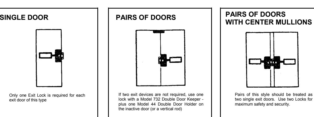
DOUBLE DOOR KEEPER MODEL 732
Applied to the surface of the inactive leaf of a pair of doors. Plated Case Aluminum 7/8" x 6"

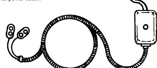
ARMORED DOOR LOOP MODEL 271
For use with Electrified locks. An easy means for bringing electric current from the hinge side of a door frame to the door. 18" flexible armored cable. End brackets are deep drawn anodized aluminum to conceal
DOUBLE DOOR HOLDER MODEL 44
wire connections.
The Double Door Holder secures the inactive door to the door frame while the active door is closed. Releasing the active door automatically allows both doors to swing freely. Reversible, right or left hand doors. Cast aluminum 8.5" long, 3" wide and 2.5" high.
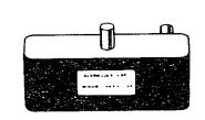
BATTERY ELIMINATOR MODEL AC-9
The AC-9 battery eliminator provides constant regulated 9VDC power for Models 250 and 260. It is simple to install and maintenance free. 117 VAC to 9VDC. The AC-9 conserves the battery which automatically takes over as the power source in the event of a power failure or intentional power cutoff.
THUMB TURN MODEL THT

Used instead of cylinder and keys to retract and project the deadbolt from inside.
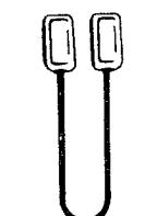
OUTSIDE ACCESS DOOR PULL MODEL 707
For access from building exteriors. Installed on the outside of the door and linked to the lock. After deadbolt is retracted by outside key, a slight pull will release the deadlatch and open door. Cast aluminum, 8" x 1.5".
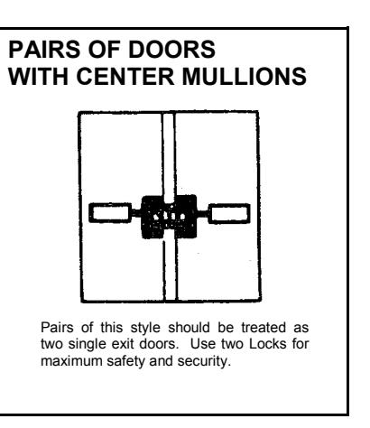
SINGLE DOOR KEEPER MODEL 730
Supplied for single doors or pairs of doors with mullions.
CYLINDER FINGER PULL MODEL 711
An inexpensive door pull for use when outside key only access is required.
RIM CYLINDER MODEL CER-OKC
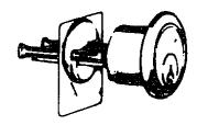
Used to lock and unlock all our exit and panic alarm locks from outside. Includes two keys for outside key control (KA or KD).
LATCH HOLDBACK DEVICE MODEL 747
An integral lock modification which "dogs" the latchbolt to provide a hold-open function. Simply depress the latchbolt beyond the face of the lock and it will remain retracted until the door is relocked by key..
STANDARD FEATURES
- •WATERPROOF
- •UNIT IS NON-HANDED
- DEADBOLT WITH HARDENED STEEL INSERT
- •DEADLATCH FOR EASY ACCESS FROM INSIDE WITHOUT ALARM
- DEADBOLT CAN BE OPERATED BY OUTSIDE KEY
- •LOCK ONLY REQUIRES 5 TO 10 LBS. OF FORCE TO OPERATE
- CAN BE USED FOR SINGLE OR DOUBLE DOORS
- LOUD DUAL PEZO HORN
- •SELECTABLE - CONTINUOUS OR TWO MIN. ALARM SHUTDOWN
- DISARMING BEEP WHEN BOLT IS RETRACTED WITH KEY
- •LOW BATTERY BEEP WHEN BATTERY NEEDS TO BE REPLACED
- RETRIGGERABLE ALARM AFTER TWO MIN. SHUTDOWN FOR MODEL 260 ONLY
INSTALLATION & OPERATING INSTRUCTIONS ELECTRONIC PANIC LOCK 250 SERIES
INSTALLATION
- 1) With the door closed, select the proper template and tape it to the inside face of the door with the center line approximately 38" above the floor per template directions.
-
2) Mark and drill the following holes (see template for details):
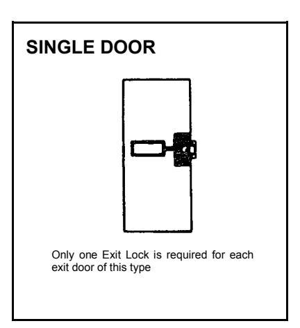
- A) FOR SINGLE AND DOUBLE DOORS : Mark six (6) .157" dia. holes, four (4) for the lock mounting plate and two (2) for the keeper.
- B) Mark a ¼" dia. hole for the rub plate on double doors 1¾" thick only.
- C) IF OUTSIDE CYLINDER (CER-OKC) IS USED : Mark the center of the 1¼" dia. hole.
- D) IF OUTSIDE PULL MODEL 707 IS USED : Mark the center of the four (4) ¼" dia. holes.
- E) If mounting the lock on a hollow metal door and wires are to be run through the door, drill hole x (see template). NOTE: If outside pull is used, drill four (4) holes ¼" dia. through the door from the inside. Then drill ¾" dia. holes 1¼" deep from the outside of the door.
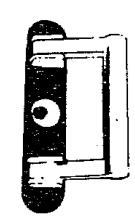
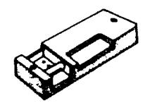
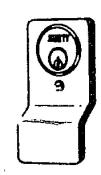
- 3) Remove the lock cover and four (4) screws holding the cylinder housing to the bolt cover. Install rim cylinder (CER) with the keyway horizontal, facing the front of the lock (nine o'clock position) and cut the cylinder tailpiece 3/8" beyond the base of the cylinder. Reinstall the cylinder housing, guiding the tailpiece into the crosshole of the cam with four (4) screws.
- 4) Use the key to test for proper operation of the deadbolt. The key should be able to be withdrawn from the lock in either the fully locked or fully unlocked position of the deadbolt. If not, the cylinder and the cam are misaligned and the cylinder housing must be removed. Turn the cam a quarter (¼) turn to the right, and reinstall the cylinder housing. ( NOTE: The deadbolt can be projected into the keeper by turning the key counter-clockwise and can be withdrawn from the keeper by turning the key clockwise one full turn.)
- 5) FOR OUTSIDE CYLINDER ONLY (CER-OKC) : Install the rim cylinder with the keyway horizontal facing the front of the door (three o'clock position) with the screws supplied and cut the tailpiece 3/8" beyond the inside face of the door.
- 6) FOR OUTSIDE CYLINDER ONLY : Guide the tailpiece of the outside cylinder into the crosshole of the outside cam.
- 7) Install the lock to the door with four (4) #10 screws as supplied.
-
8)
FOR SINGLE DOOR ONLY
: Remove the keeper cover, roller, and pin. Install the keeper base on the door with two (2) screws supplied. Reinstall the pin, roller and cover with two screws.
- FOR DOUBLE DOOR ONLY : Install the rub plate for a 1¾" wide door, from inside the door. Also install the 732 keeper with two (2) #10 screws supplied. Do not tighten the screws fully because the keeper will require adjustment as mentioned in instruction 9.
-
9)
FOR SINGLE DOOR ONLY
: Close the door, project the deadbolt and adjust the keeper so that the door is tightly latched. Retract the deadbolt, hold the keeper, release the latch and open the door Open the keeper cover and tighten the screws. Drill a .157" dia. hole, as shown on template, for the holding screw, and fasten the keeper with a #10 screw. Reinstall pin, roller and cover with two screws.
- FOR DOUBLE DOOR ONLY : Close the door, project the bolt and adjust the plastic slide on the 732 keeper so the door is tightly latched and tighten the screws.