Alarm Lock Lever and Return Spring Upgrade Kit
Open the original PDF document
View PDF

LEVER AND RETURN SPRING UPGRADE KIT
WI2008 4/12 © ALARM LOCK 2012 Publicly traded on NASDAQ Symbol: NSSC www.alarmlock.com
THIS LEVER RETURN SPRING RETROFIT KIT APPLIES TO EXIT TRIM AND MORTISE LOCKS ONLY
Note: This kit should be installed by experienced lock professionals only. Be careful not to misplace the small components.
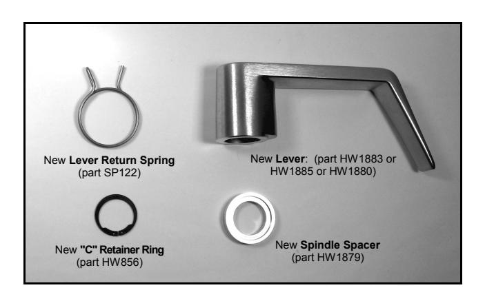
Kit contents:
- New Lever Return Spring (part SP122)
- New Spindle Spacer (part HW1879)
- New "C" Retainer Ring (part HW856)
- New Lever : (part HW1883 or HW1885 or HW1880)
Required Tools:
- Phillips Screwdriver
- Small flat blade screwdriver
- Snap Ring Pliers
- White lithium or any high quality grease
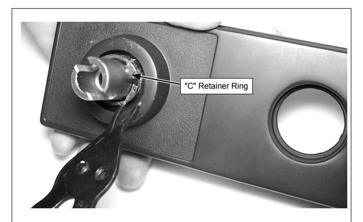
1. Remove lever and outside housing from door. Remove the key cylinder (Exit Trim only). Remove "C" Retainer Ring from front of lock with snap ring pliers. Discard old "C" Retainer Ring.
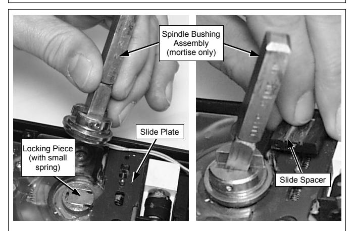
3. Remove the Spindle Bushing Assembly (mortise only). Remove the Locking Piece and the small spring attached to it. Also remove the Slide Spacer. Note location of Slide Plate.
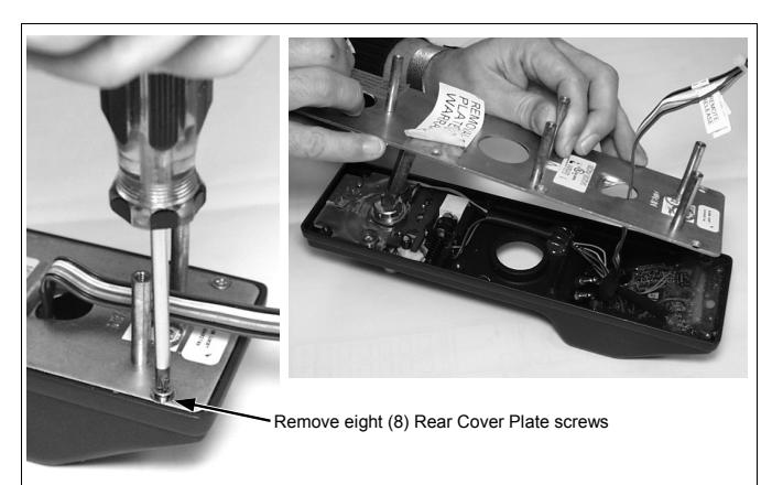
2. Unscrew the eight screws from the Rear Cover Plate as shown and remove. When the Rear Cover Plate is removed, keep the lock flat as shown as to prevent small parts from falling out of the housing.
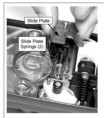
4. Remove Slide Plate. Remove the two Slide Plate Springs. Note: Certain early models have a white Post Bushing; remove if present and set aside. Leave the black Post Bushing installed.
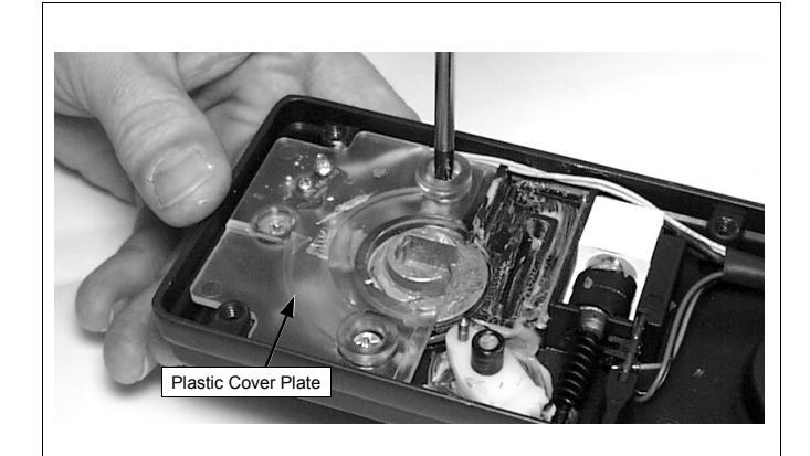
5. Remove the 3 screws that hold down the Plastic Cover Plate. Carefully remove the Plate and set aside.
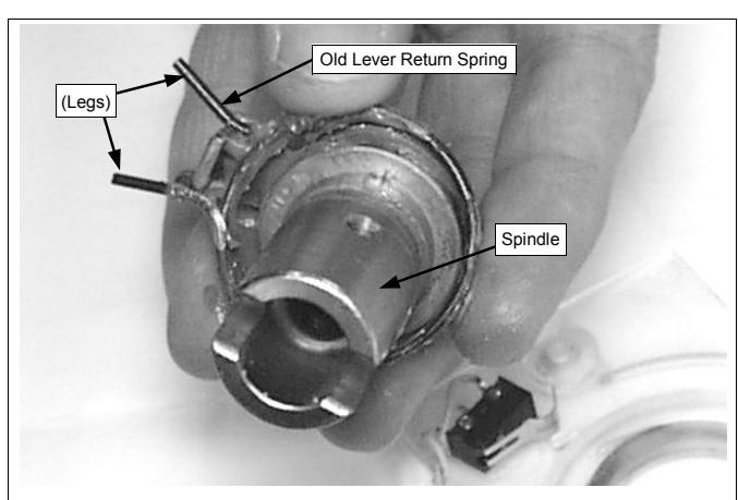
6. With the "C" Retainer Ring and Plastic Cover Plate removed, the Spindle can easily slide out. Remove and discard the old Lever Return Spring.
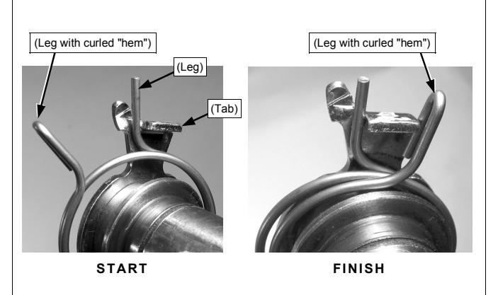
7. Thoroughly grease new Lever Return Spring and install EXACTLY as shown. See next step for close-up image.
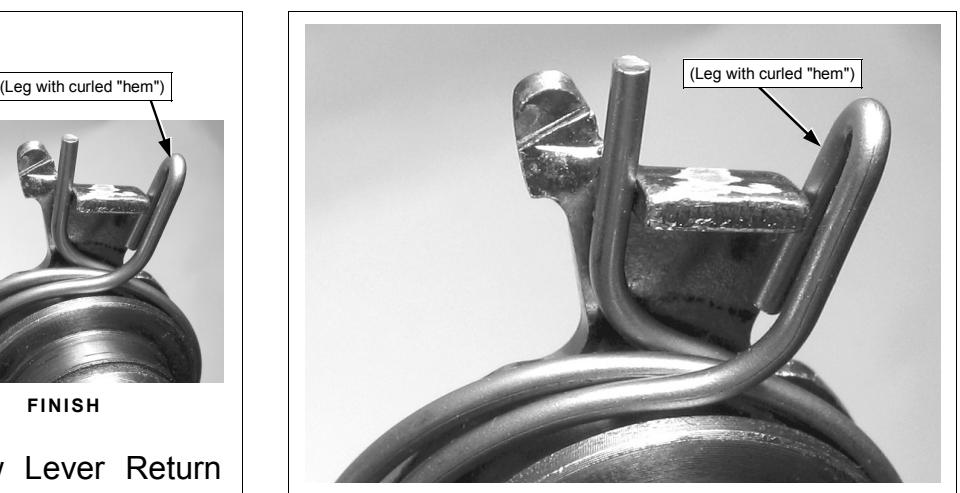
8. ( Note: For clarity, Spring is shown without grease). Also note the location of the leg with the curled "hem".

9. Slide the Spindle back into place as shown.
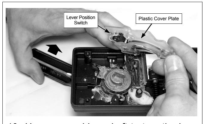
10. Use a screwdriver shaft to turn the lever in the direction of the arrow. Carefully replace the Plastic Cover Plate. Ensure the Lever Position Switch wires run to the side and are out of the way. Release lever.
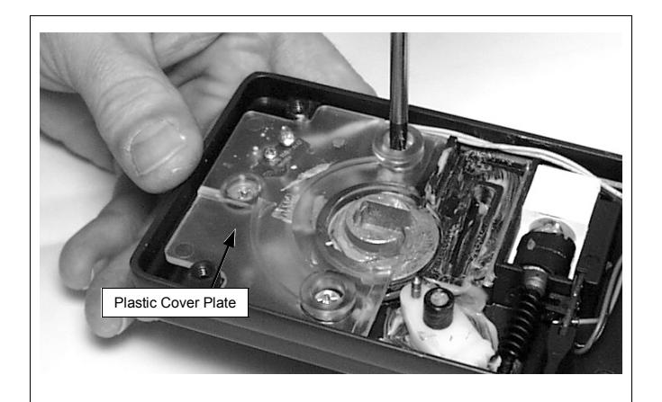
11. Insert the 3 screws that hold down the Plastic Cover Plate. Note: Do NOT push Spindle from front as damage to the Plastic Cover Plate may occur.
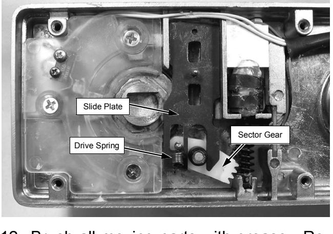
12. Brush all moving parts with grease. Replace Slide Plate. Be sure to hook the end of the small Drive Spring to the white Sector Gear as shown.
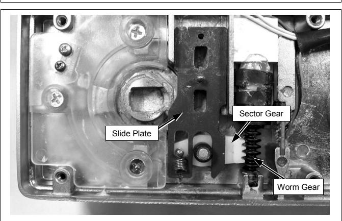
13. Hold Slide Plate in place. Turn the Worm Gear until the white Sector Gear centers in the Worm Gear threads. The Slide Plate moves as the worm gear turns.
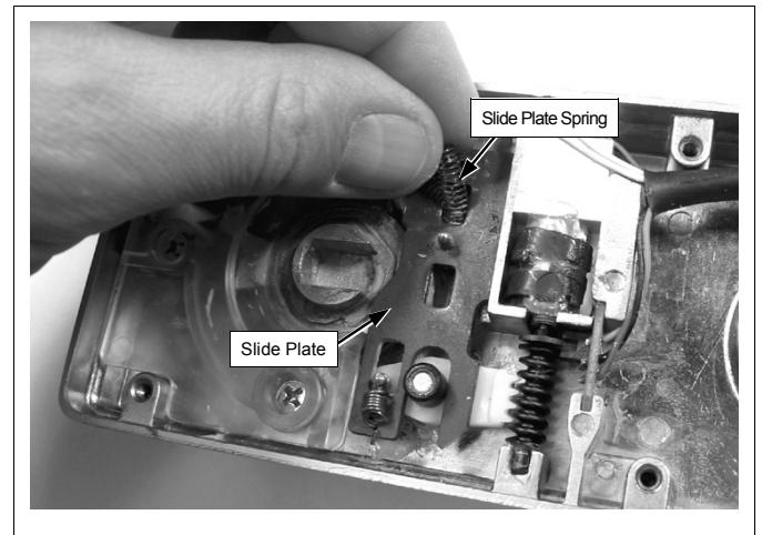
14. Insert one of the two Slide Plate Springs into opening of the Slide Plate as shown.
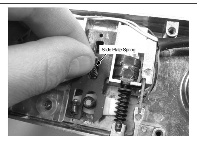
15. Insert the second Slide Plate Spring into the other opening of the Slide Plate as shown.
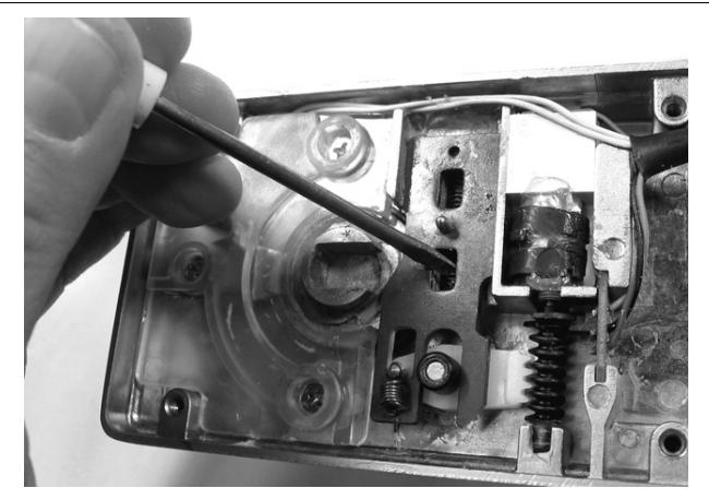
16. Use small screwdriver to compress the second Slide Plate Spring . Be sure Spring is fully inserted into opening.
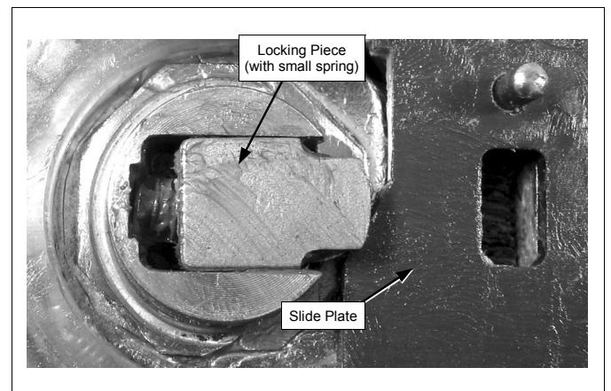
17. Replace Locking Piece as shown. Insert its small spring first and push down to lock in place.
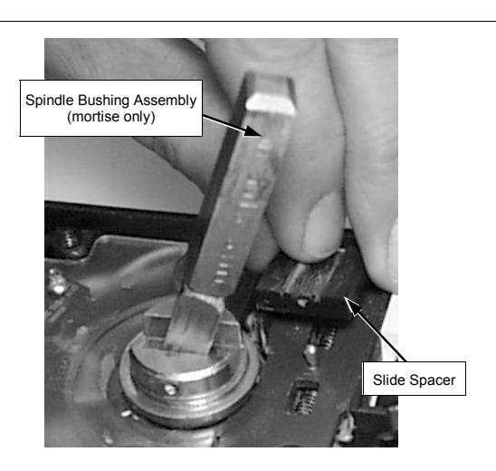
18. Replace the Spindle Bushing Assembly (mortise only). Replace the Slide Spacer.
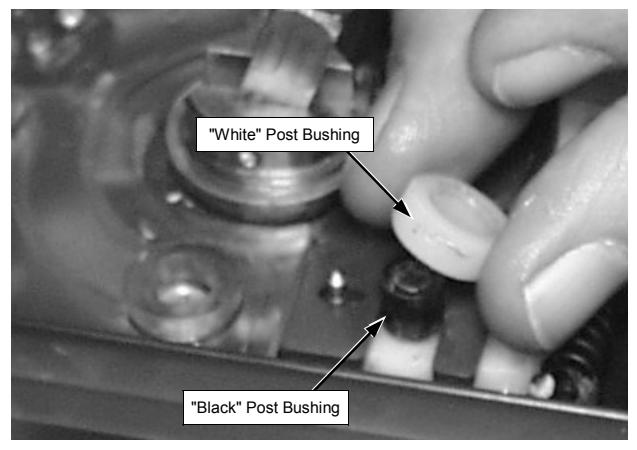
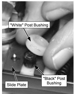
19. Ensure the white Post Bushing is replaced. Note: Certain early models have a white Post Bushing in addition to the black Post Bushing.
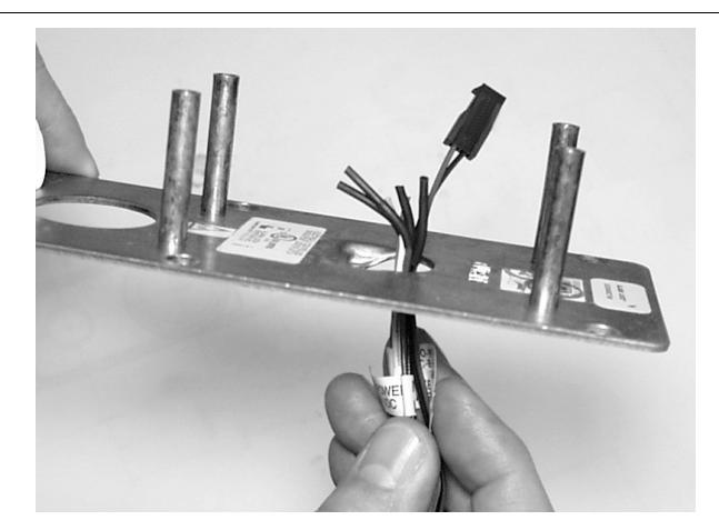
20. Insert wires through the Rear Cover Plate as shown and secure the Plate with eight (8) screws.
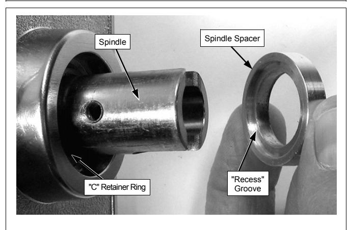
21. Install new "C" Retainer Ring. FULLY insert the new Spindle Spacer with its "Recess" groove facing the spindle.
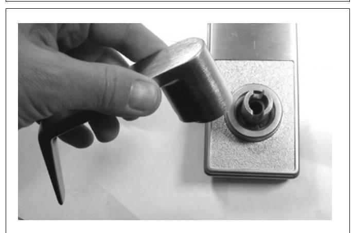
22. Re-install the new lever provided.