Alarm Lock ETDLN, ETPDLN, Installation Instructions for Sargent Models 8800, 12-8800, 8888, 12-8888, WS-8800, & 12-WS 8800
Open the original PDF document
View PDFET-PDLN
Networx Trilogy ® Panic Exit Device Trim
(Mount Battery Box Above Exit Trim Device)
Sargent
Models 8800, 12-8800, 8888, 12-8888, WS-8800, & 12-WS 8800 Series Rim Exit Device
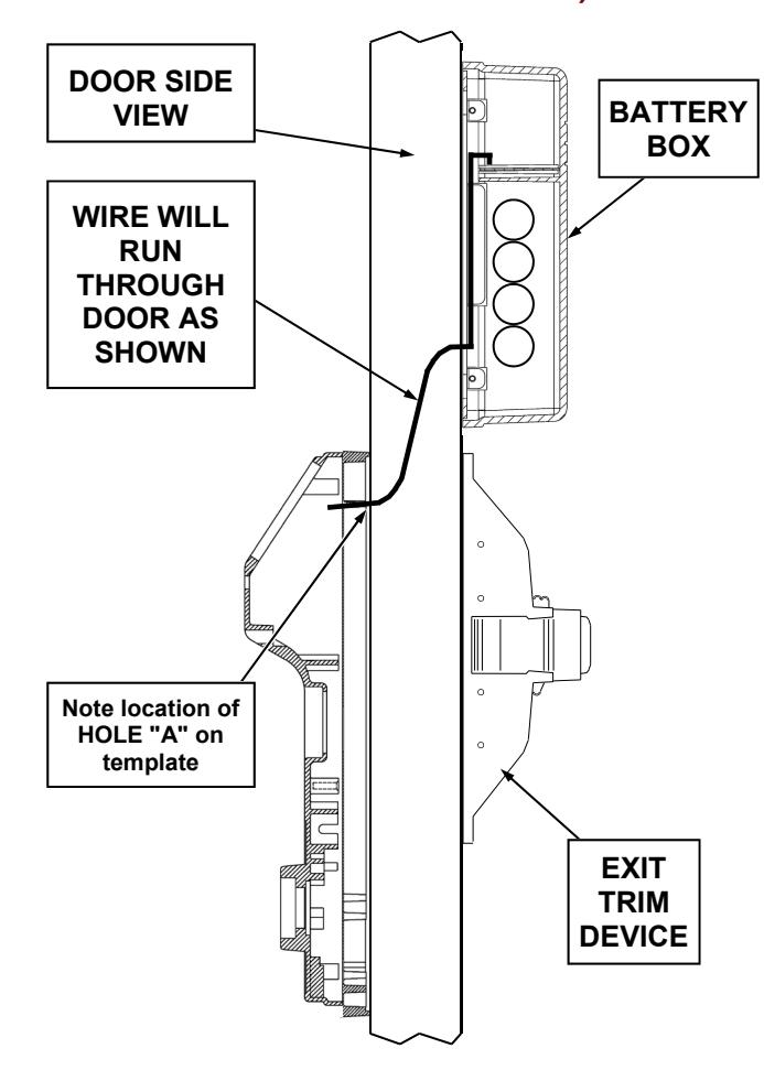
Mount Battery Box ABOVE Sargent Device
START HERE:
1. Tools Needed:
For new installations, see exit device instructions. For existing installations: Tape measure, drill, drill bits 5/16", 3/4" and 1/4" with extra-long shaft, Phillips screwdriver #2 & #3, level, 1" hole saw (for rim cylinder installations).
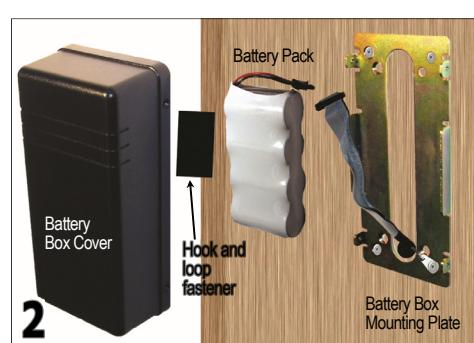
2. Identify Battery Box Parts. See above image for Battery Box parts.
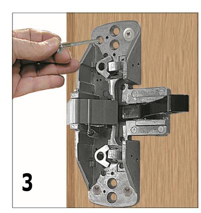
3. Existing Installation: Remove Sargent exit device from door.
Prepare Templates: If you are using templates printed from an computer PDF file, templates must be printed without size modifications and verified for dimensional accuracy. To ensure correct scale, measure the dimensions of the box ENSURE THIS IS ½INCH
indicated on the template (example shown ½INCH
4. Align Holes with Template
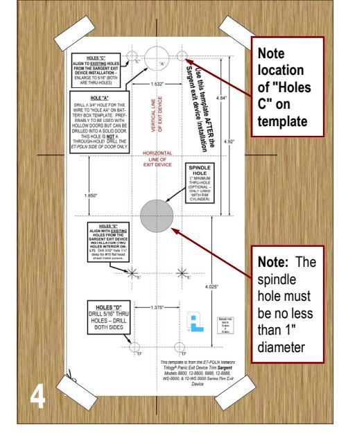
Existing Installation: Position Alarm Lock template (shown above) on horizontal & vertical lines of Sargent exit device. Also align existing holes in door to "HOLES E" on template.
New Installations: Locate and mark horizontal and vertical lines indicated in the Sargent Exit Device Template , and temporarily install Sargent Exit Device on door using the Sargent installation instructions. Remove Sargent Exit Device. Position Alarm Lock template (shown above) on horizontal & vertical lines of Sargent exit device. Also align "HOLES E" to holes used to secure the Sargent Exit Device, and tape template to door.
Mark Holes: On the template, mark hole centers on each side of door for HOLES "C" and "D". Also mark "HOLE A" on the ET-PDLN side of the door only ( "Hole A" is NOT a thru-hole ). If installing a rim cylinder, mark the 1" "SPINDLE HOLE" (thru-hole) as indicated.
Drill Holes:
Drill thru-holes "C" and "D" from both sides of door to avoid splintering. For hollow doors , drill "HOLE A" on the ET-PDLN side of the door ONLY (NOT a thru-hole). For solid wood doors , drill "HOLE A" on the ET-PDLN side of the door ONLY about 1/2" deep (NOT a thru-hole). Note: The other end of "HOLE A" is "HOLE AA" to be drilled in the next step.
Take a moment to note the location of "HOLES C" on the template and on both sides of the door (HOLES "C" are thru-holes); these holes will be used again in the next step.
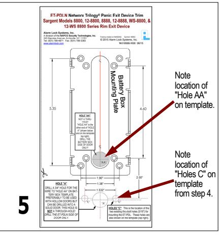
5. Mark Holes with Template
Battery Box Mounting Plate Template (shown above): Recall the location of "Holes C" in step 4 on the exit device side of the door (same side the Battery Box will be mounted). Align the "Holes C" referenced on the Battery Box template to the "Holes C" on the exit device side of the door. Mark the location of "Hole AA" and the holes for the Battery Box Mounting Plate.
For hollow doors , use a 3/4" drill bit and drill "Hole AA" into the Sargent exit device side of the door ONLY (NOT a thru-hole). For solid wood doors , use a 3/4" drill bit and drill "Hole AA" about 1/2" into the Sargent exit device side of the door. Using a 1/4" drill bit with an extra-long shaft, drill from "Hole AA" to "Hole A". Enlarge this 1/4" hole to 3/4" using the 3/4" drill bit.
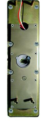
6. Before positioning the Exterior assembly on door , feed the ribbon cable and the green ground wire (with ring connector) through the 3/4" wire hole. Do not pinch or cut wires. Position the Exterior assembly on door.
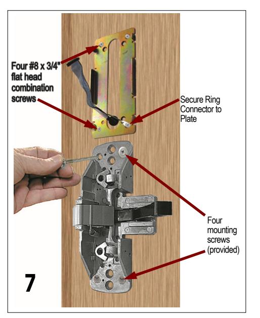
7. Replace Exit Device , insert and fasten with 4 new mounting screws (do not over-tighten).
Mount the Battery Box Mounting Plate with four #8 x 3/4" flat head combination screws, using one of the screws to secure the green ground wire ring connector to the Plate .
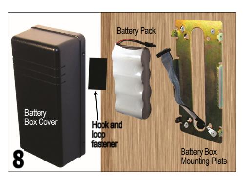
8. Connect the Battery Pack (batteries may be shrink wrapped as shown or may be inside a housing) and place inside of Battery Box Mounting Plate. Secure the Battery Pack inside the Battery Box Cover with the hook and loop fastener (provided). Position the Cover and fasten with four #6-32 x 5/16" screws.
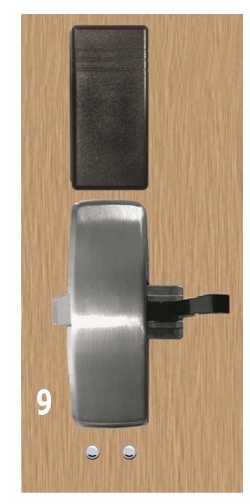
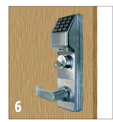
9. Replace and fasten exit device & battery box covers.
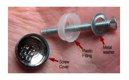
Mounting the Battery Box above the Sargent exit trim results in two exposed screw heads ("Holes D") from the Exterior assembly of the ET-PDLN lock. Cover the two screw heads with the screw covers provided. Insert metal washer and plastic fitting into screw as shown, and install screw into the Exterior assembly threads inside "Holes D". Then snap the plastic cap onto the screw head/plastic fitting (light taps from a small hammer may be necessary).
Check lock for proper operation before closing door.
To Change Cylinder

IMPORTANT:
When replacing cylinder, be sure to use the proper Cylinder Adapter and Tailpiece.
Alarm Lock Systems, Inc. A division of the NAPCO Security Technologies, Inc. 345 Bayview Avenue, Amityville, NY 11701 Tel: (631) 789-4871 Fax: (631) 789-3383 www.alarmlock.com
Publicly traded on NASDAQ Symbol: NSSC
at right).
A. Remove Cover plate. Rotate the spindle either direction to expose
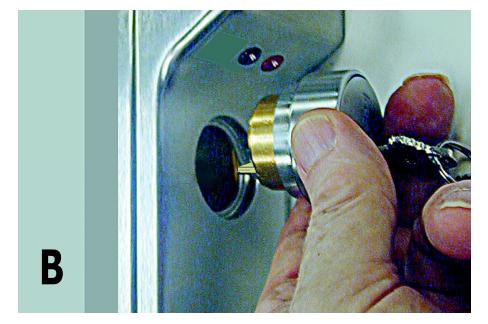
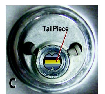
and remove cylinder screws. B. Remove old cylinder and insert new cylinder. C. Note: The tailpiece must be in the horizontal position as shown in the image above.