Alarm Lock EG35-70 Exitgard Installation Instructions
Open the original PDF document
View PDF
- 10. Test lock operation by projecting deadbolt by key into keeper. Depress cross bar fully to retract deadbolt release latchbolt, and open door.
- door is tightly latched. After final adjust the keeper so the door is tightly latched. After final adjustments, install holding screw in keeper to maintain position permanently. On pairs of doors, adjust plastic slide on keeper so door is tightly latched.
If installing Model 35 (No Alarm) ignore instruction #12.
- 12. Connect power plug. Repeat step #10. Horns should sound until deadbolt is projected by key. Attach self adhesive sign to bar and door.
- 13. Replace lock cover, turn over keys and this sheet to owners' representative.

INSTALLATION INSTRUCTIONS FOR EXITGARD®
Model 35 Panic Lock Model 70 Panic Alarm Lock
825-405-001
P3190
- With door closed, tape template to inside face of door with center line approximately 38" above the floor. Mark all hole locations with punch or awl. Note that keeper is surface installed...cn jamb for single doors, on other leaf of pairs of doors.
- If outside cylinder is being used, mark cylinder hole center. If Alarm Lock Pull #707 is furnished, mark the 4 holes on the template for the pull in addition to the cylinder hole.
- Crill holes as indicated for lock and keeper. Drill holes for outside cylinder and for outside pull if used.
- 4. Loosen hex head boit holding cross bar to lock and pull bar off clapper arm. Remove lock cover screws. Depress latchbolt. Lift up and remove lock cover.
- 5. (Disregard if cylinder or thumb turnalready installed). Remove screws holding cylinder housing (Figure A) to bolt cover. Install rim cylinder with keyway horizontal facing the front of the lock (opposite the slot in the rear of the cylinder support). Cut cylinder tailpiece %" below base of cylinder support Reinstall support while guiding the tailpiece into the slot in the cam.
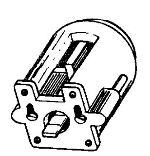
Figure A
- 6. Use key to:ry proper operation. Key should withdraw in either the fully locked or fully unlocked position of the deadboit. If not, the cylinder and cam are 'mistimed'. The cylinder housing must be removed, the cam turned a quarter turn to the right and the cylinder housing reinstalled.
- Attach the lock to the door. For single doors, remove the keeper cover and roller, install keeper, replace roller and cover. Double doorkeeper #732 is installed on the surface of the inactive leaf as furnished.
- 8. Remove hinge pivot cover. Reinstall push bar section on the lock clapper as far forward as it will go Tighten hex head bolt under lock clapper. Attach hinge side pivot assembly, using a level or tape to assure crossbar is level. If cross bar is loo long, loosen hex head bolt on under side of clapper and remove pivot assembly. Cut bar to proper length, deburr edges, and reinstall pivot assembly on the cross bar. Only after pivot base has been installed should 'Dogging Screw' (Figure B) be loosened and the pivot block removed and discarded.
- 9. Dog screw should 'ace floor. If not, remove and reinstall from below. Replace pivot cover with hole for dog screw facing the floor.
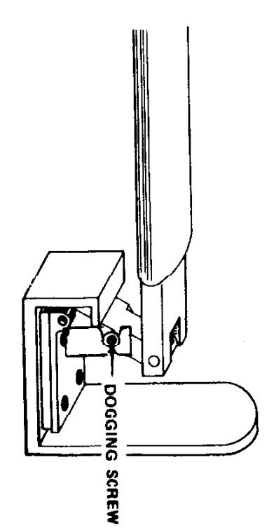
Figure B