Alarm Lock DL6200, PDL6200 and PDL8200 Installation Instructions
Open the original PDF document
View PDF

345 Bayview Avenue Amityville, New York 11701 For Sales and Repairs 1-800-ALA-LOCK For Technical Service 1-800-645-9440 or visit us at http://tech.napcosecurity.com/ (Note: Technical Service is for security professionals only) Publicly traded on NASDAQ Symbol: NSSC
© ALARM LOCK 2016
Wireless Trilogy® DL6200, PDL6200 & PDL8200
with Door Monitoring Installation Instructions
WI2024B 07/16

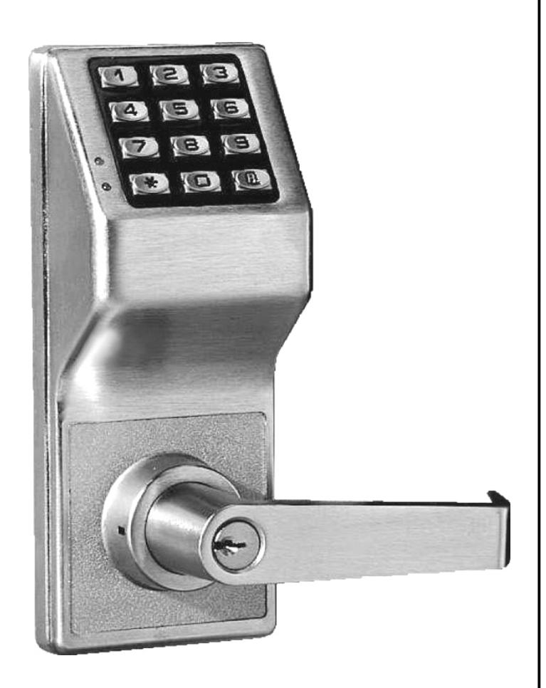
DL6200
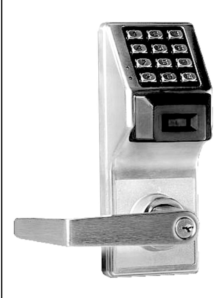
Wireless Trilogy Series Network Access Control Systems PDL Series with ProxCard® Access
TABLE OF CONTENTS
| Wireless Lock Configuration Overview3 | Interchangeable (IC) Locks 8 |
|---|---|
| Ordering Information3 | Install Interchangeable (IC) Cores 8 |
| Door Preparation4 | Changing an Existing IC Core 9 |
| Installation Jig4 | Removing the IC Core and Lever 9 |
| Latch Installation4 | Programming10 |
| Strike Installation5 | Troubleshooting10 |
| Door Contact (Magnet) Installation5 | Wire Connections10 |
| Lock Preparation5 | Wiring and Power Up10 |
| Lock Installation5 | Power Up11 |
| Adjusting for Door Thickness6 | Erase All Programming11 |
| To Reverse Lever Handing6 | Battery Replacement11 |
| Install Inside Trim6 | Warranty12 |
| Attaching Levers and Locksets9 |
Note: ProxCard® and ProxKey® are trademarks of the HID© Corporation. Windows is a registered trademark of the Microsoft Corporation. Other products, product names and services described in this manual are for identification purposes only and may be trademarks of their respective companies.
WIRELESS LOCK CONFIGURATION OVERVIEW
PDL6200 / DL6200 / 8200 Series
The Trilogy Networx™ PDL6200, DL6200 and PDL8200 series door locks are essentially the same as the 6100 series wireless door locks, but with added Door Monitoring features as follows:
- Entry Logged: A valid credential entered;
- Exit Logged: Inside (protected) lever turned;
- Door Ajar: A valid credential entered and the door opened but not closed within the programmed time specified;
- Forced Entry: Door opens without a valid credential entered or door opened without the inside lever being turned.
For Door Ajar and Forced Entry, the internal relay can be programmed to engage, and for Door Ajar an Alert Sounder can be programmed to sound (Forced Entry always sounds the Alert Sounder). In addition, the PDL6200, DL6200 and PDL8200 locks allow you to upload and download programming features wirelessly using a computer connected to a computer network. With "wireless" communication, the various cables and/or AL-DTM Data Transfer Module devices are NOT required to transfer data. You can use your computer to retrieve logs, download User Codes and program features into and out of each wireless door lock in your installation. The 8200 series locks are essentially identical to the 6200 series locks, but are equipped with a 13.56MHz Smart Card reader.
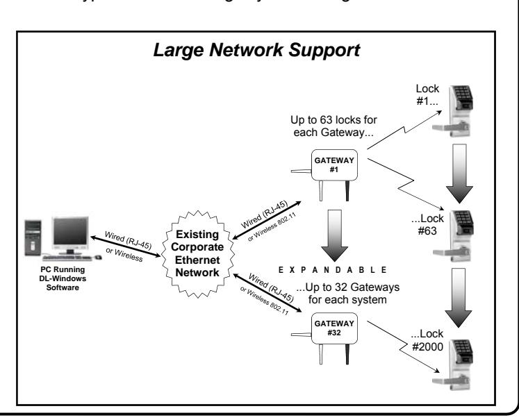
DL-Windows software is installed on a computer that is connected to a computer network; connected to this network is an intermediate device called a Gateway that communicates to a radio located inside each door lock. In this way, the software allows full programming and control of each lock in the system.
To ensure each physical lock is identified correctly by DL-Windows, the factory assigns each lock a unique serial number; after locks are installed in the doors and the Gateways are mounted, the Gateways search for new locks, allowing them to be enrolled into the system.
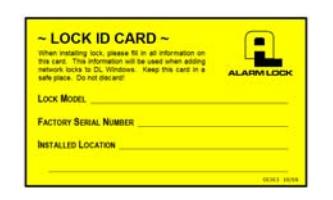
For every new wireless lock installed on a door, we strongly recommend that you fill out a new yellow-colored "Lock ID Card" (shown above) with the installation location, lock model and serial number. These ID cards are a convenient way to keep track of and ensure all locks are enrolled in the DL-Windows Account.
Up to 63 locks for each Gateway... PC Running DL-Windows Software EXPANDABLE Lock #1... ...Lock #63 ...Lock #2000 Router Small Network Support ...Up to 32 Gateways for each system GATEWAY #32 GATEWAY #1
Flexible Setup
In addition to wireless communication, these wireless door locks can also be programmed at the keypad . This means that locks can be installed on the doors and immediately be put into use via keypad programming --even before a wireless network is set up. Therefore, you can install the locks on the doors before configuring the wireless network, or you can set up the wireless network first and add locks later. If you wish, you can even start by designing a "virtual" system within DL-Windows (creating new Accounts, adding Users and configuring lock features, etc.), then set up the network and install the lock hardware later. But in the end, after your lock hardware is physically installed and the network is up and running, you can run DL-Windows to link the "virtual" system saved on your computer with the "real" lock hardware on the doors.
Note: Keypad programming of User Codes, Features, Time Zones, and Schedules is available as a temporary convenience to allow the lock to be put into use before installing and configuring a wireless network. Therefore, all lock programming added via the keypad cannot be retrieved into DL-Windows. If you decide to start programming your wireless lock via the keypad, we recommend you keep hardcopy records (in a secure location) of all Users, their User Codes, and any proximity cards that may have been programmed. Keeping complete and accurate records saves time because after the wireless network is set up, any programming added via the keypad must be re-added to DL-Windows and downloaded back to the lock(s).
Ordering Information
PDL6200/26D - Cylindrical Trilogy® Networx™ Wireless Access Control Lock with built in HID Proximity ID Card Reader, fullmetal digital keypad, integral bi-directional radio, 4 C-cell battery -operated (batteries supplied), serial number ID card, standard format SCI keyway for manual key override, 4⅞" ASA Strike (included). Magnetic Door Contacts included.
DL6200/26D - Cylindrical Trilogy Networx PIN-Code Wireless Access Control Lock, as above, with full-metal digital keypad only. Magnetic Door Contacts included.
PDL8200/26D - Same as PDL6200/26D above, but equipped with a 13.56MHz Smart Card reader.
This manual includes the hardware installation instructions for the PDL6200, DL6200 and PDL8200 door locks. The diagrams below detail the typical small and large system configurations.
DOOR PREPARATION
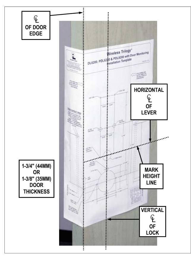
FIG. 1: FOLD AND PLACE TEMPLATE ON DOOR
- 1. Fold and place template on high edge of door at the recommended height from floor. See Fig. 1.
- 2. Mark hole centers on door and door edge.
- 3. Drill 3/8" thru-bolt holes first, then drill the 2-1/8" hole.
For Hardwood Doors:
Notch on both sides of the 2-1/8" hole to accommodate mounting plate tabs.
For Hollow Metal Doors:
Requires horizontal and vertical lock and latch case support (provided by door manufacturer).
4. Drilling the hole for the supplied Door Contact (labeled " DOOR CONTACT PREP " on template) is only necessary if the two white "Remote Input" wires inside the lock (see Fig. 14) will be used for Door Monitoring. If the Door Monitoring features will NOT be programmed, and the two white "Remote Input" wires will either not be used or used for a "Remote Release" only, there is NO need to drill the Door Contact hole. ( Note: Lock programming is performed after lock is installed on the door; in addition, these instructions will henceforth assume the Door Contact will need to be installed ).
Door Contact Hole: For Hardwood Doors:
Drill a 1/4" hole in door edge to the 1" hole as shown in Fig. 2. Then use a ¾" bit to enlarge this hole to a depth of ⅞" to allow the Door Contact to fit flush.
Door Contact Hole: For Hollow Metal Doors:
Drill a ¾" hole into the metal surface of the door edge. IMPORTANT: Be sure to remove all metal burrs from connector cable hole-- sharp edges will eventually wear away wire insulation .
5. Drill all remaining holes in template as required.
INSTALLATION JIG
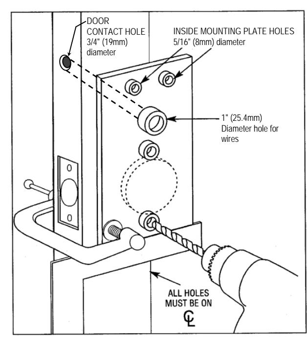
FIG. 2: ALARM LOCK INSTALLATION JIG
- 1. If the 2-1/8" hole already exists, use optional Alarm Lock Installation Jig to ensure accurate locating and drilling of 3/8" and 5/16" thru-bolt holes.
- 2. For best results, align the Installation Jig to door with a square and clamp to door before drilling See Fig. 2. Note: Always protect the door surface from damage when using jigs, clamps and other tools.
LATCH INSTALLATION
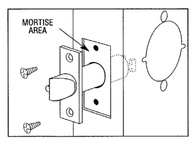
FIG. 3: LATCH INSTALLATION
- 1. Drill 1" diameter hole for latch.
- 2. Mortise for latch front. Insert latch and fasten with two screws supplied.
Note: It is important that both 1" hole and the 2-1/8" hole be on the same horizontal center line.
STRIKE INSTALLATION
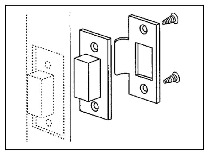
FIG. 4: STRIKE INSTALLATION
- 1. Align strike with the latch.
- 2. Trace strike outline on the door jamb.
- 3. Mortise jamb and install dust box and strike.
DOOR CONTACT MAGNET INSTALLATION (JAMB)
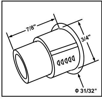
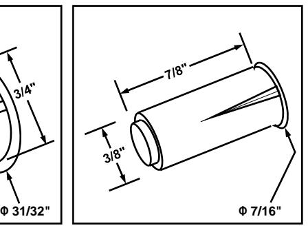
FIG. 4A: INSERT DOOR CONTACT (MAGNET) IN JAMB
- 1. With the door closed, place a mark on the inside door jamb directly opposite the Door Contact hole drilled in the door.
- 2. For one of the two Door Contact (magnet) types provided with your lock, note its dimensions in the image above. Drill into the door jamb as follows:
For Hardwood Jambs:
- For the thinner contact (above right image): Drill a 3/8" hole 7/8" deep for the magnet side of the Door Contact.
- For the thicker contact (above left image): Drill a 3/4" hole 7/8" deep for the magnet side of the Door Contact.
For Hollow Metal Jambs:
Use either a 3/8" or 3/4" bit (depending on type) to drill a hole into the surface for the Door Contact.
Insert the magnetic Door Contact in the hole; the contact sits flush with the jamb when fully inserted. Ensure a secure fit by using adhesive appropriate for the material.
LOCK PREPARATION
Separate the inside housing from the outside housing as follows:
1. See Fig. 6 for an image of the inside lever catch. Depress the inside lever catch by inserting the lever release pin through the oval hole located in the inside housing and through the small round hole in the lever shaft. While depressing the lever catch, pull off the lever (jiggle lever if needed).
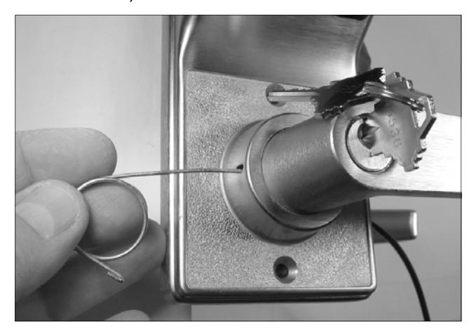
FIG. 5: INSERT LEVER RELEASE PIN TO DEPRESS THE LEVER CATCH
2. Depressing this lever catch also allows the inside housing to be separated from the outside housing. Use a small screwdriver to depress the lever catch (the lever catch is circled in Fig. 6) and pull the inside housing away from the outside housing.
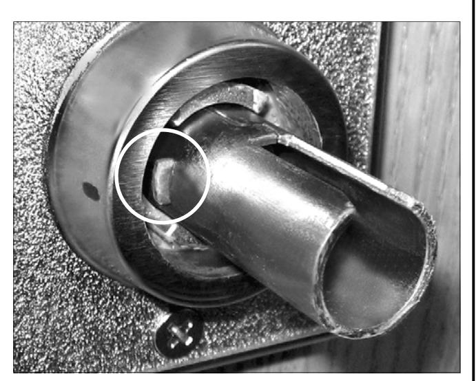
FIG. 6: PUSH IN LEVER CATCH (CIRCLED)
LOCK INSTALLATION
INSTALL OUTSIDE LOCK BODY
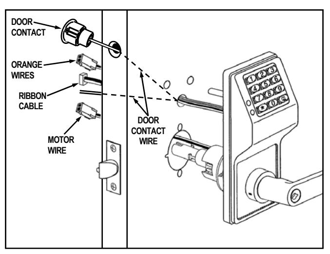
FIG. 7: INSTALL OUTSIDE LOCK BODY
- 1. Insert motor wire plug through the large 2 1/8" hole; insert the ribbon cable and Lever Monitor Switch plug (orange wires) through the 1" hole as shown in Fig. 7. Insert Door Contact wires into hole in door edge and pull wires through the 1" hole as shown in Fig. 7.
- 2. Insert outside lock body into door and be sure to properly engage the lock body with the latch as shown in Fig. 8.
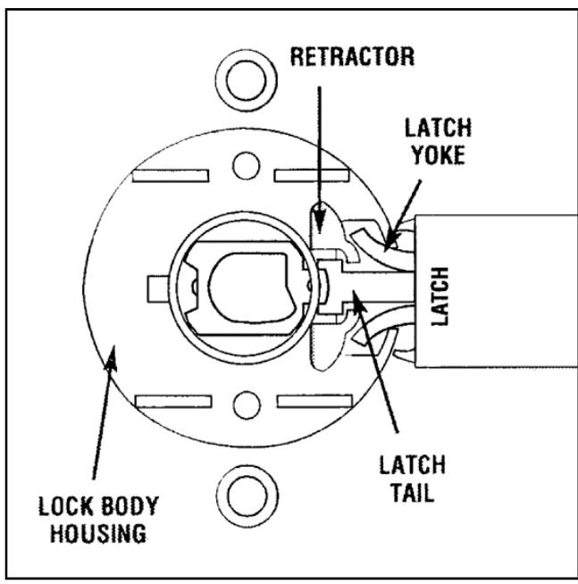
FIG. 8: VIEW FROM INSIDE OF DOOR
The latch yoke must engage the lock body housing and the tailpiece must engage the retractor.
ADJUSTING FOR DOOR THICKNESS
Plastic spacers either add or subtract the distance between the rose plates. Each spacer represents 1/8" of door thickness. Locks are factory assembled for 1 3/4" thick doors using 3 plastic spacers.
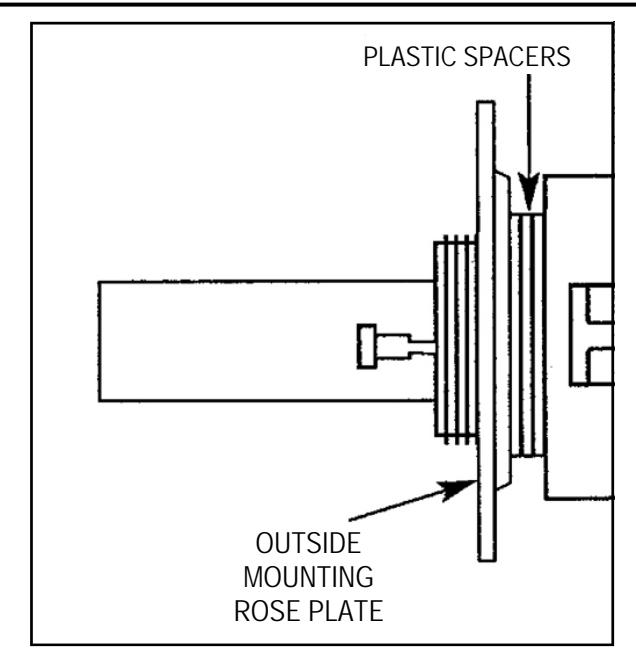
FIG. 9: ADJUST DOOR THICKNESS
For other door thicknesses:
- 1. Remove outside lever as follows: Insert key into outside cylinder, turn clockwise 45 degrees. Depress the outside lever catch by inserting the lever release pin through the oval hole located in the outside housing and through the small round hole in the lever shaft. While depressing the lever catch, pull off the lever (jiggle lever if needed).
- 2. Remove outside housing and unscrew outside rose plate. For 1 5/8" door, remove one plastic spacer. For 1 7/8" door, add one plastic spacer.
- 3. Screw mounting rose plate up to the spacers.
- 4. Reassemble outside housing and lever. For other door thicknesses, consult factory.
TO REVERSE LEVER HANDING
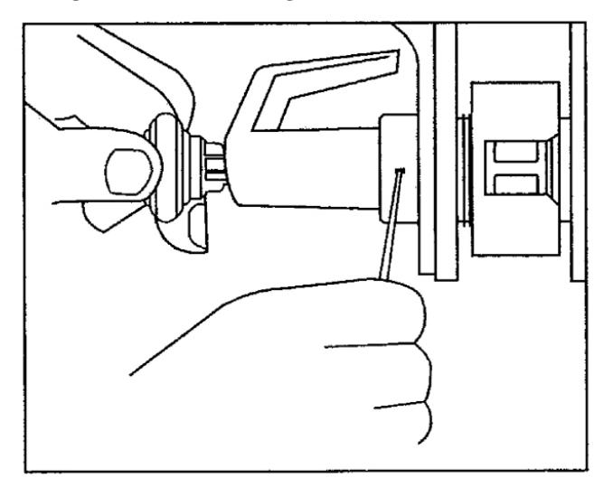
FIG. 10: REVERSE LEVER HANDING
With the inside lever and housing off:
1. Insert key into outside cylinder, turn clockwise 45 degrees and depress the lever catch. Pull lever off.
- 2. Use the outside spindle to rotate the lock body 180 degrees. Be sure lever catch (shown in Fig. 6) faces the door edge. If necessary, depress the lever catch to allow the outside spindle to rotate 180 degrees.
- With key in cylinder untouched (still at 45 degrees clockwise), position lever on spindle and press until lever catch engages. Remove key and test lever for proper engagement by turning and pulling. For IC models, see Fig. 20.
INSTALL INSIDE TRIM
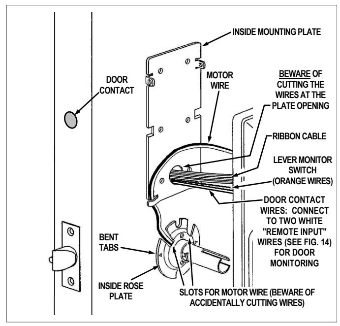
FIG. 11: INSTALL INSIDE TRIM
1. Place the inside rose plate over spindle and on door. Align the two slots with the two 3/8" holes in door (the rose plate is marked with "TOP", circled in Fig. 12) and the bent tabs facing door (the bent tabs bite into wooden doors, preventing its rotation; for metal doors, drill small holes to allow the rose plate to sit flush against door). Fasten with two 8-32 x 1 1/4 Phillips pan head screws through the inside rose, engaging the outside lock body. Do not over-tighten.
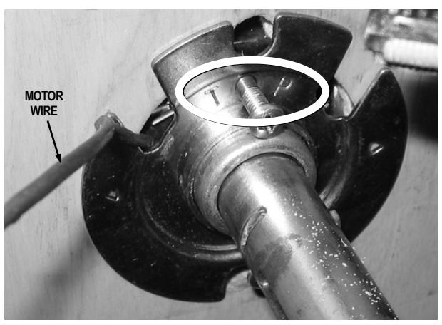
FIG. 12: INSIDE ROSE PLATE INSTALLATION
Position inside mounting plate and, without pinching or cutting the wires, pull the Door Contact wires, the ribbon cable and the Lever Monitor Switch plug (orange wires) through the mounting plate opening.
The two white "Remote Input" wires (see Fig. 14) can be programmed as a "Remote Release" or for "Door Monitoring" (programming is performed after lock is installed on the door):
- When a "Remote Release" is desired (factory default), connect the two white "Remote Input" wires inside the lock to a normally open contact switch (switch is shorted/closed to unlock the lock).
- When "Door Monitoring" is desired, connect these two white "Remote Input" wires to the supplied Door Contact wires (when the door is closed the contacts are also "closed").
Note: After physically installing the lock, see the programming instructions Function 67 "Door Ajar Monitor On" and/or "Forced Door Detect On".
Fasten inside mounting plate with two 6 x /4 flat head sheet metal screws and two 8-32 x 1 flat head machine screws as shown in Fig 13 (do not over-tighten). The two bottom screws are optional. Note: Be sure the mounting plate is perfectly vertical before installing sheet metal screws. See Fig. 13 for screw locations. Note: As you tighten the screws, the inside mounting plate pulls in and secures the outside lock body to the door.
IMPORTANT: See Fig. 11 and 13: The motor wire must come through either slot and be secured by the motor cable notch without pinching or cutting the wire.
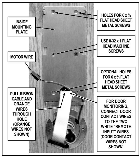
FIG. 13: INSIDE MOUNTING PLATE INSTALLATION
3. See Fig. 14. Before placing the inside housing onto the lock, connect the Lever Monitor Switch plugs (orange wires), plug the ribbon cable, motor wire and Auxiliary Power/Remote Input plug into their receptacles on the inside housing circuit board (these plugs and sockets fit only one way--do not force them). Seal the connectors with dielectric grease (included). Do not allow the wires to cross or lay on top of each other. Jiggle the connector cable to be sure the wire opening does not pinch wires before fastening bolts.
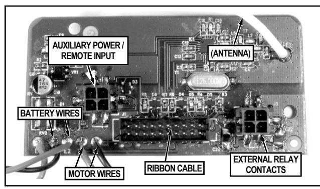
FIG. 14: RECEPTACLES LOCATED IN THE INSIDE HOUSING
4. Place inside housing over the spindle (see Fig. 15). Depress the lever catch (use a screwdriver pointed inside the spindle) and push housing flush against door. Be sure that all wires are through the housing before tightening the two 10-32 x 2 1/4" thrubolts.
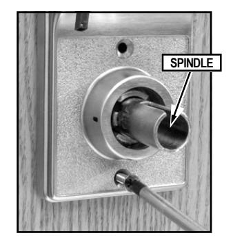
FIG. 15: TIGHTEN THRU-BOLTS
5. Secure the top of the inside housing to the inside mounting plate with two black 4-40 x ¼ flat head Phillips or spanner head security screws. See Fig. 16.
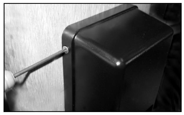
FIG. 16: SECURE TOP OF INSIDE HOUSING
6. Plug the battery connector into its receptacle. See Fig. 17. Upon connection of the battery pack, you will hear three beeps.
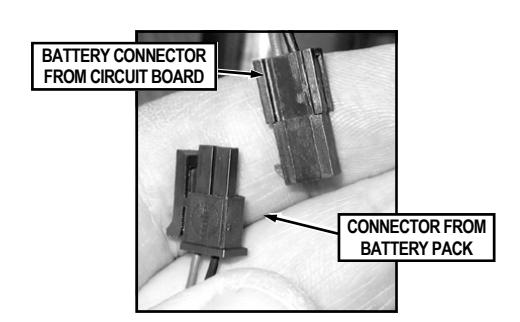
FIG. 17: CONNECT THE BATTERY PACK
7. Insert the battery pack into inside housing as shown in Fig. 18.
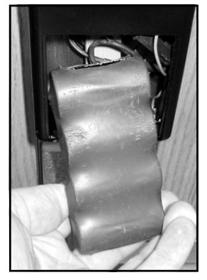
FIG. 18: INSERT BATTERY PACK INTO HOUSING
8. Secure the battery cover to the inside housing with two black 4-40 x ¼ flat head Phillips or spanner head security screws. See Fig. 19.
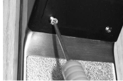
FIG. 19: SECURE BATTERY COVER
ATTACHING LEVERS AND LOCKSETS
Interchangeable Core (IC) Models:
Skip to the section, "INTERCHANGEABLE (IC) LOCKS" below.
Standard Levers and Cylinders:
Standard levers and standard lock cylinders are both included in non-IC lock models.
a. Install the tailpiece, cylinder retainer and cylinder into the standard lever as shown in Fig. 20.
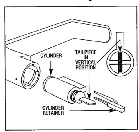
FIG. 20: STANDARD CYLINDER-LEVER, TAILPIECE AND RETAINER.
- b. Attach the outside lever by first inserting the metal key into the outside lock cylinder and turning the key 45° in either direction.
- c. Insert the lever on the spindle and push the lever in until it engages with the lever catch (it may be necessary to turn the key back and forth while installing the lever).
- d. Install the inside lever in the same manner as the outside.
- e. Test both levers to be sure they are on securely and operate without binding. Be sure the outside key retracts the latch when the key is turned in either direction.
BE SURE TO TEST THE LEVERS AND CYLINDERS FOR PROPER OPERATION BEFORE CLOSING DOOR.
INTERCHANGEABLE (IC) LOCKS
Interchangeable (IC) cores require special levers. If necessary, remove both standard levers (with their standard cylinders) before proceeding. (To remove standard levers, insert key into cylinder, turn key 45° in either direction, depress the lever catch and pull off lever). Interchangeable (IC) cores and their specialized levers are both available from your Alarm Lock dealer.
INSTALL INTERCHANGEABLE (IC) CORES
- 1. Insert outside IC lever on spindle and push in until it engages with the lever catch.
- 2. Insert control key in IC core and turn clockwise.
- 3. Insert IC core tailpiece (shown in Fig. 21 and Fig. 22) into interchangeable core. Use ONLY an Alarm Lock© IC core tailpiece.
- 4. With control key in IC core, insert core fully into lever.
5. Turn key counterclockwise and remove control key.
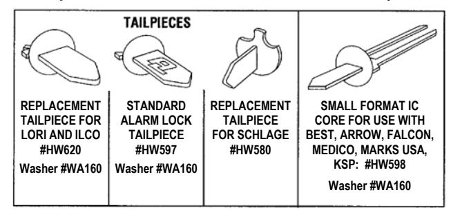
FIG. 21: STANDARD AND IC CORE TAILPIECE VARIETIES
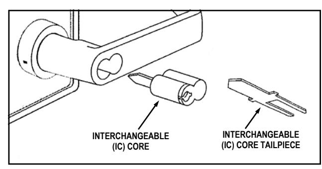
FIG. 22: INSTALL INTERCHANGEABLE (IC) CORE
CHANGING AN EXISTING IC CORE
- 1. Remove the existing IC core by inserting its control key, then turning the key clockwise and pulling the key to remove the core. Set core aside.
- 2. Insert Alarm Lock IC tailpiece with washer into new core.
- 3. Insert new control key into new core, turn clockwise.
- 4. Insert new core into lever and turn key counterclockwise to lock in position.
- 5. Remove new control key.
REMOVING THE IC CORE & LEVER
- 1. Remove the existing IC core by inserting the control key, then turning the key clockwise and pulling the key to remove the core.
- 2. Use a screwdriver to CAREFULLY push inside of lever catch to the side (see Fig. 23). Pull off the IC lever.
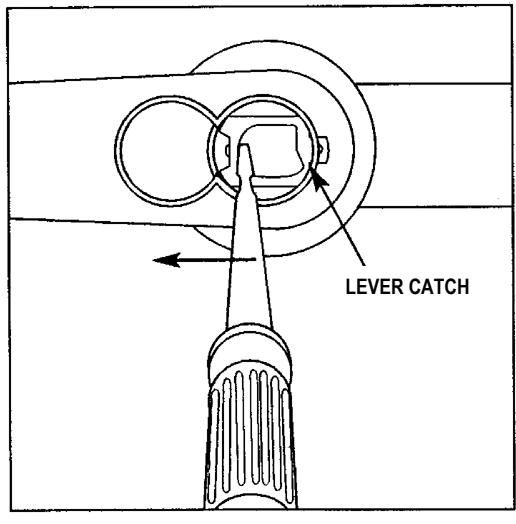
FIG. 23: REMOVING THE IC CORE LEVER
PROGRAMMING
Your lock can be programmed (and re-programmed again and again) to suit your changing requirements. Instead of distributing metal keys, distribute User Codes -- and delete them from the lock firmware when needed. To program your DL/PDL6200 and PDL8200 lock, see the lock programming instructions.
TROUBLESHOOTING
Electronic Trouble:
Lock incorrectly operates in reverse.
Solution: Reverse motor wires in connector.
Lock will not accept new codes during programming.
Solution: Disconnect battery connector, hold down any button until lock resets, then reconnect and start programming again.
Lock drains batteries quickly.
Solution: Check all wires for pinching or cutting. Check for water damage. If condition persists, consult factory.
Lock is inoperative.
Solution: Check batteries for proper polarity and check for cut wires.
Lock sounds "steady tone" (with red flickering LED) during lock operation.
Solution: Low battery signal - replace batteries.
Mechanical Trouble:
Lever pulls off.
Lever Catch not fully engaged. Lock is not centered on door. Door too thick. (See Fig. 9).
Unable to assemble outside lever.
Key and tailpiece orientation are incorrect (See Fig. 21 and 22).
Latch will not fully retract.
Lock is not properly engaged with latch or misaligned. Lock is not centered on door (See Fig. 8).
Key binds in lock.
Lever Catch not fully engaged. Lock is not centered on door. Check for proper tailpiece and proper orientation of tailpiece (See Fig. 21 and 22).
WIRE CONNECTIONS
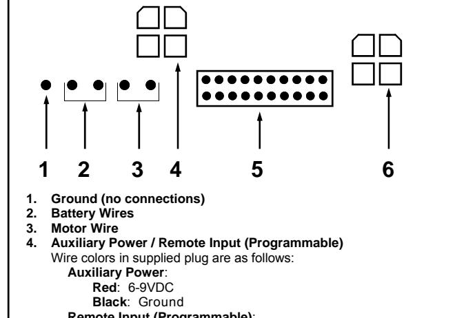
Remote Input (Programmable) :
Two White Wires can be used for either a "Remote Release" or for "Door Monitoring" functions:
- For " Remote Release " (factory default): Wire to a N/O contact switch (short to unlock the lock).
- For " Door Monitoring ": Connect to the supplied Door Contact wires. Note: When the door is closed the contacts are also "closed". See the below " WIRING AND POWER UP ", Remote Input description for more details.
- 5. Ribbon Cable
- 6. External Relay Contacts
FIG. 24: WIRE CONNECTIONS
WIRING AND POWER UP
External Power:
Red / Black wires - External 7.5 VDC Power Source must be used for operation without batteries.
Remote Input:
White / White wires - The two white wires can be programmed for use as a "Remote Release" or programmed for "Door Monitoring" (programming is performed at the lock keypad after lock is installed on the door). When programmed for a " Remote Release " (factory default), wire to a N/O contact switch that is closed/shorted to unlock the lock. When programmed for " Door Monitoring ", connect wires to the supplied Door Contact wires ( Note: When the door is closed the contacts are also "closed"). For Door Monitoring functions, see Function 67 in the lock programming instructions for more information. Door Monitoring functions include " Door Ajar Monitor On " (Function 67, option 40) and " Forced Door Detect On " (Function 67, option 42).
Relay:
COM-Orange / NO-Green / NC-Yellow - See Function 67 in the programming instructions for programming options for the Relay.
Wiring to Disarm a Burglary Control Panel:
See the programming instructions WI1790 for additional information.
POWER UP
- 1. When applying power to the lock for the first time, stop and follow the procedure outlined in "Quick Start, First time Power Up" further in this manual.
- 2. When power is re-applied to a lock that was already operational, proceed as follows:
- 3. Disconnect battery pack connector.
- 4. With battery power disconnected, press and hold down ; for 10 seconds to insure discharge of all capacitors.
- 5. Re-connect battery pack (lock will sound 3 short beeps). If beeps are not heard, then restart at step 1.
- 6. Do not press any keys for 15 seconds.
- 7. After 15 seconds, the LED will flash red 6 times and 6 beeps will sound.
- 8. The lock is now ready for use. The pre-existing program is loaded from fixed memory. Set the clock using functions 38, 39 and 40.
ERASE ALL PROGRAMMING
(The "out of box" factory default will be loaded)
- 1. Remove the battery pack.
- 2. With battery power disconnected, press and hold down ; for 10 seconds to ensure discharge of all capacitors.
- 3. Re-install the battery pack (lock will sound 3 short beeps). If beeps are not heard, then restart at step 1.
- 4. Within 5 seconds after hearing the 3 short beeps, press and hold ; until the lock begins to beep, then release.
- 5. A series of 5 RED LED and 5 beeps will be heard followed by 10 seconds of silence, then 3 GREEN LED's and 3 fast beeps.
All settings and programming have been erased and the lock is now ready for use. Note: All lock programming can also be erased (without need to disconnect the batteries) by entering Function 99.
BATTERY REPLACEMENT
When a valid code is entered and the batteries are weak, the red LED will turn on and the sounder will sound a steady tone. Always replace weak batteries as soon as possible.
CAUTION: Do not press any keys while batteries are disconnected or you may erase the real-time clock settings.
- 1. At the back of the lock, remove the screw at the bottom of the lock housing and remove the cover.
- 2. Pull out the battery pack and quickly replace with a new battery pack - within 1 minute.
- 3. If you do not hear the 3 beeps when power is reapplied, all programming and settings have been retained, and the lock is ready for use. Go to step 5.
- 4. If you do hear 3 beeps when power is re-applied, do not press any keys for 15 seconds. After the 15 second period, the LED will flash red 6 times and 6 beeps will sound. Reset the clock using functions 38, 39 and 40.
- 5. Replace the cover and tighten the screw.
ALARM LOCK LIMITED WARRANTY
ALARM LOCK SYSTEMS, INC. (ALARM LOCK) warrants its products to be free from manufacturing defects in materials and workmanship for twenty four months following the date of manufacture. ALARM LOCK will, within said period, at its option, repair or replace any product failing to operate correctly without charge to the original purchaser or user.
This warranty shall not apply to any equipment, or any part thereof, which has been repaired by others, improperly installed, improperly used, abused, altered, damaged, subjected to acts of God, or on which any serial numbers have been altered, defaced or removed. Seller will not be responsible for any dismantling or reinstallation charges, environmental wear and tear, normal maintenance expenses, or shipping and freight expenses required to return products to ALARM LOCK. Additionally, this warranty shall not cover scratches, abrasions or deterioration due to the use of paints, solvents or other chemicals.
THERE ARE NO WARRANTIES, EXPRESS OR IM-PLIED, WHICH EXTEND BEYOND THE DESCRIPTION ON THE FACE HEREOF. THERE IS NO EXPRESS OR IMPLIED WARRANTY OF MERCHANTABILITY OR A WARRANTY OF FITNESS FOR A PARTICULAR PUR-POSE. ADDITIONALLY, THIS WARRANTY IS IN LIEU OF ALL OTHER OBLIGATIONS OR LIABILITIES ON THE PART OF ALARM LOCK.
Any action for breach of warranty, including but not limited to any implied warranty of merchantability, must be brought within the six months following the end of the warranty period.
IN NO CASE SHALL ALARM LOCK BE LIABLE TO ANY-ONE FOR ANY CONSEQUENTIAL OR INCIDENTAL DAMAGES FOR BREACH OF THIS OR ANY OTHER WARRANTY, EXPRESS OR IMPLIED, EVEN IF THE LOSS OR DAMAGE IS CAUSED BY THE SELLER'S OWN NEGLIGENCE OR FAULT.
In case of defect, contact the security professional who installed and maintains your security system. In order to exercise the warranty, the product must be returned by the security professional, shipping costs prepaid and insured to ALARM LOCK. After repair or replacement, ALARM LOCK assumes the cost of returning products under warranty. ALARM LOCK shall have no obligation under this warranty, or otherwise, if the product has been repaired by others, improperly installed, improperly used, abused, altered, damaged, subjected to accident, nuisance, flood, fire or acts of God, or on which any serial numbers have been altered, defaced or removed. ALARM LOCK will not be responsible for any dismantling, reassembly or reinstallation charges, environmental wear and tear, normal maintenance expenses, or shipping and freight expenses required to return products to ALARM LOCK. Additionally, this warranty shall not cover scratches, abrasions or deterioration due to the use of paints, solvents or other chemicals.
This warranty contains the entire warranty. It is the sole warranty and any prior agreements or representations, whether oral or written, are either merged herein or are expressly cancelled. ALARM LOCK neither assumes, nor authorizes any other person purporting to act on its behalf to modify, to change, or to assume for it, any other warranty or liability concerning its products.
In no event shall ALARM LOCK be liable for an amount in excess of ALARM LOCK's original selling price of the product, for any loss or damage, whether direct, indirect, incidental, consequential, or otherwise arising out of any failure of the product. Seller's warranty, as hereinabove set forth, shall not be enlarged, diminished or affected by and no obligation or liability shall arise or grow out of Seller's rendering of technical advice or service in connection with Buyer's order of the goods furnished hereunder.
ALARM LOCK RECOMMENDS THAT THE ENTIRE SYS-TEM BE COMPLETELY TESTED WEEKLY.
Warning: Despite frequent testing, and due to, but not limited to, any or all of the following; criminal tampering, electrical or communications disruption, it is possible for the system to fail to perform as expected. ALARM LOCK does not represent that the product/system may not be compromised or circumvented; or that the product or system will prevent any personal injury or property loss by burglary, robbery, fire or otherwise; nor that the product or system will in all cases provide adequate warning or protection. A properly installed and maintained alarm may only reduce risk of burglary, robbery, fire or otherwise but it is not insurance or a guarantee that these events will not occur. CONSEQUENTLY, SELLER SHALL HAVE NO LIA-BILITY FOR ANY PERSONAL INJURY, PROPERTY DAMAGE, OR OTHER LOSS BASED ON A CLAIM THE PRODUCT FAILED TO GIVE WARNING. Therefore, the installer should in turn advise the consumer to take any and all precautions for his or her safety including, but not limited to, fleeing the premises and calling police or fire department, in order to mitigate the possibilities of harm and/or damage.
ALARM LOCK is not an insurer of either the property or safety of the user's family or employees, and limits its liability for any loss or damage including incidental or consequential damages to ALARM LOCK's original selling price of the product regardless of the cause of such loss or damage.
Some states do not allow limitations on how long an implied warranty lasts or do not allow the exclusion or limitation of incidental or consequential damages, or differentiate in their treatment of limitations of liability for ordinary or gross negligence, so the above limitations or exclusions may not apply to you. This Warranty gives you specific legal rights and you may also have other rights which vary from state to state.