Alarm Lock DL2700 Installation Instructions
Open the original PDF document
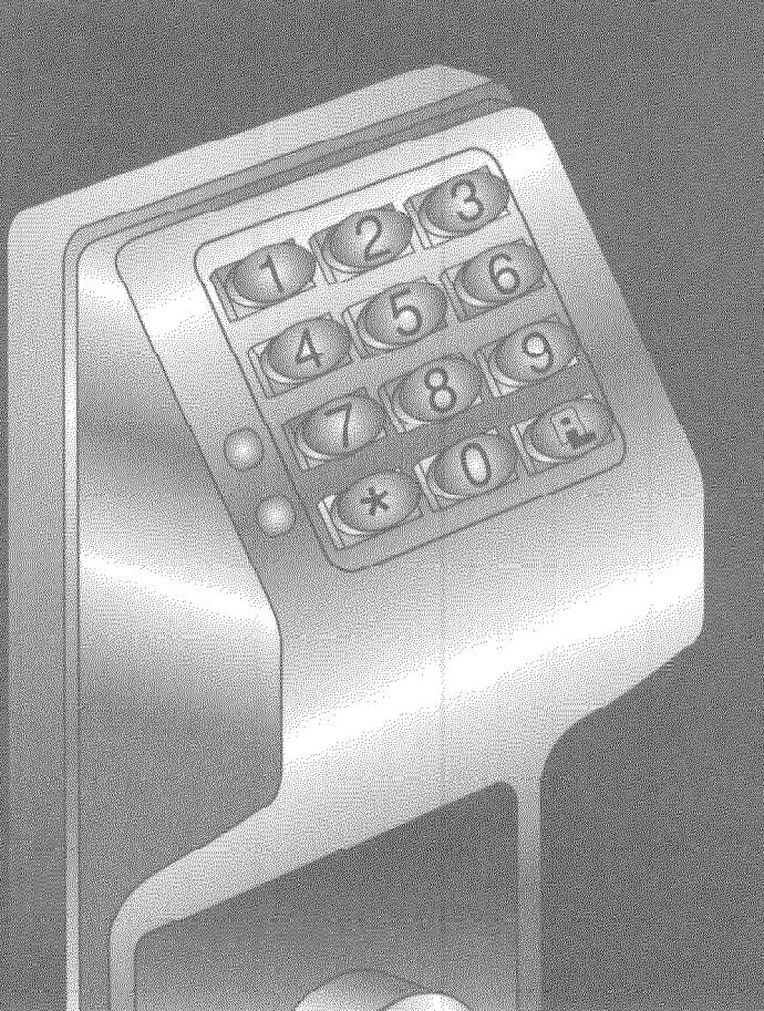
View PDFMODEL DL2700 INSTALLATION INSTRUCTIONS

TRILOGY
THE KEYLESS ELECTRONIC LOCKSET

THE KEYLESS ELECTRONIC LOCKSET
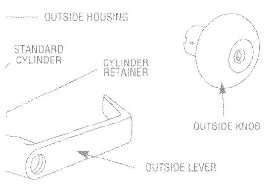
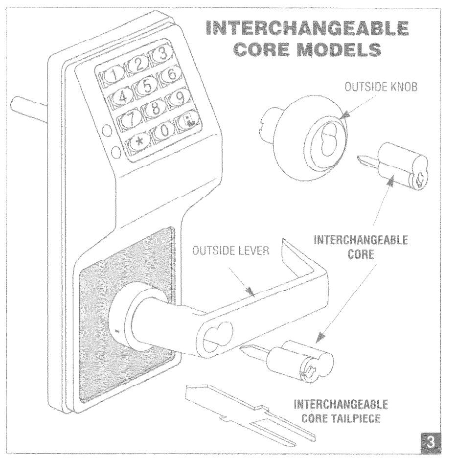
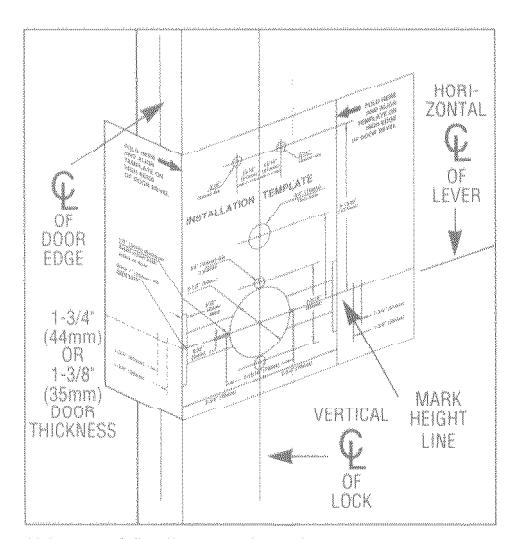
FIG. 1. DOOR PREPARATION:
- 1. Fold and place template on high edge of door at the recommended height from floor.
- 2. Mark hole centers on door and door edge
- 3. Drill 3/8" Thru-Bolt holes first, then drill 2-1/8" hole.
FOR HARDWOOD DOORS:
Notch on both sides of 2-1/8" hole to accommodate mounting plate tabs.
FOR HOLLOW METAL DOORS require horizontal and vertical lock and latch case support. Provided by door manufacturer.
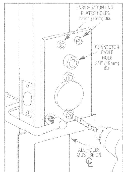
FIG. 2. ALARM LOCK INSTALLATION JIG
- 1. If 2-1/8" hole exists, use optional Alarm Lock Installation Jig to insure accurate locating and drilling of 3/8" Thru-Bolt holes.
- For best results, align the Installation Jig to door with a square and clamp to door before drilling.
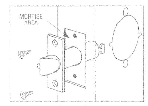
FIG. 3. LATCH INSTALLATION
Drill 1" diameter hole for latch. Mortise for latch front. Insert latch and fasten with two screws supplied.
NOTE: It is important that both 1" and 2-1/8" holes be on the same horizontal center line.
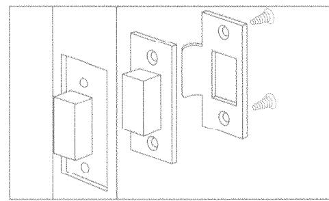
FIG. 4. STRIKE INSTALLATION
- 1. Align strike with latch.
- 2. Trace strike outline on door lamb.
- 3. Mortise jamb and install strike and dust box.
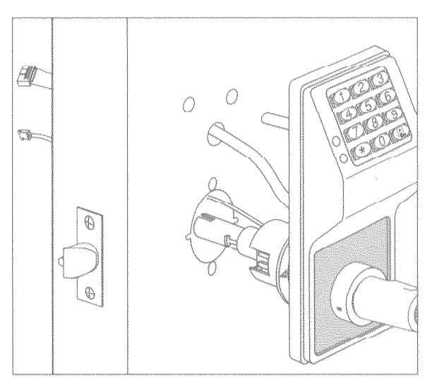
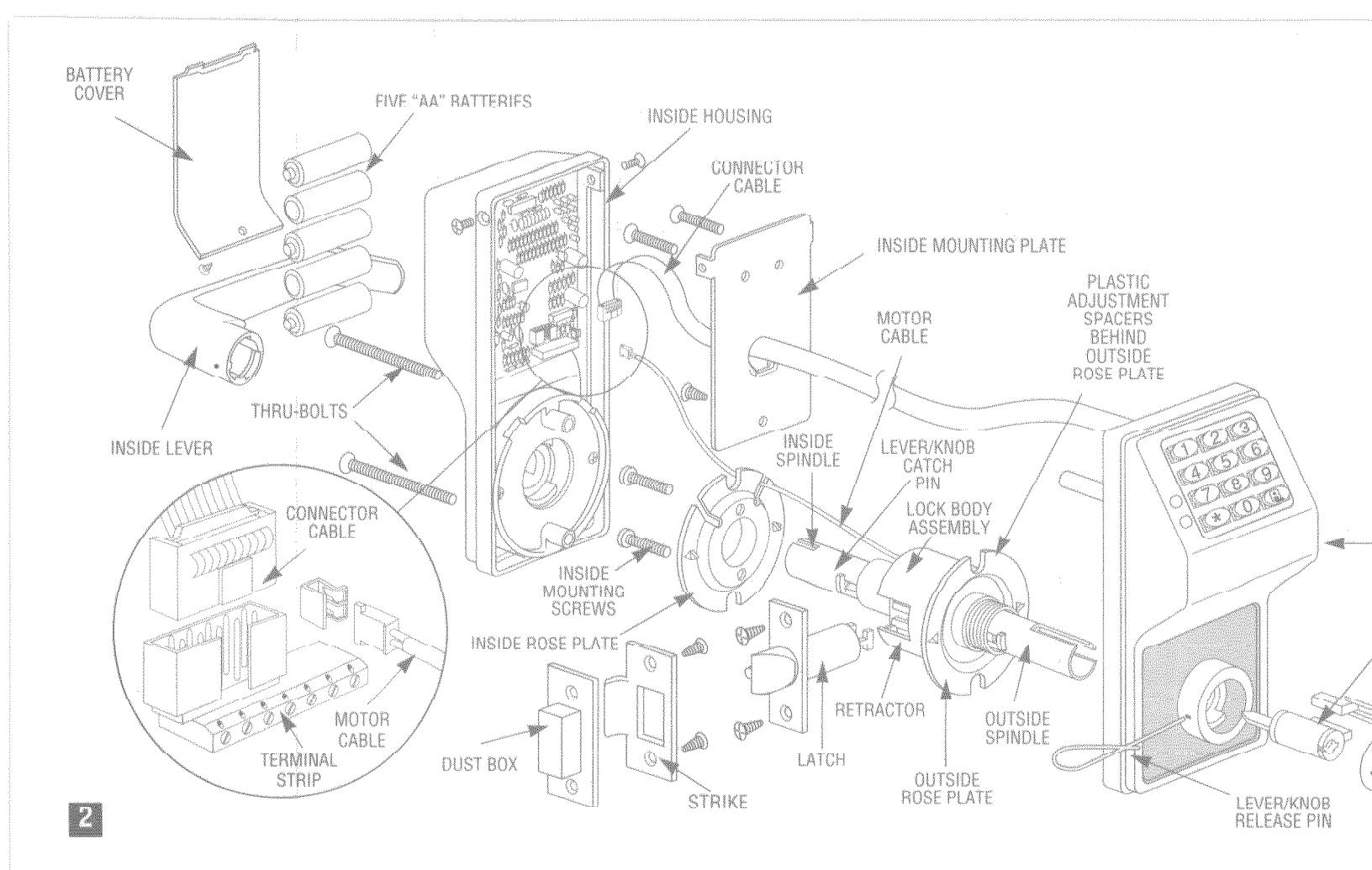
FIG. 5a. PREPARING LOCK FOR INSTALLATION
- Insert the Lever/Knob Catch Pin into hole in the inside housing, depress Lever/Knob Catch and pull off lever/knob.
- With the same pin depress the Lever/Knob Catch again to remove the inside housing.
FIG. 5b. INSTALLING OUTSIDE TRIM ASSEMBLY (Lever, Housing & Lock body)
- 3. With inside lever & housing removed insert Motor wire through 2-1/8" hole & Connector wire through the 3/4" hole.
-
4. Insert Outside trim assembly into door and be sure to properly engage the lock body with the latch.
- See "View from inside of door" diagram.
- Latch Yoke must engage lock housing and tailpiece must engage Retractor.
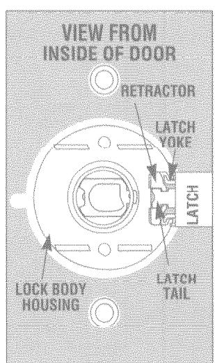
FIG. 6. TO REVERSE HANDING
With the inside Lever and Housing off:
- Insert key into outside cylinder & turn 45°, depress Lever/Knob Catch & pull Lever/Knob off.
- 4. Rotate lock body 180°. Be sure Lever/knob catch faces the door edge. If necessary depress Lever/Knob Catch & rotate outside spindle 180°.
- 6a. Replace lever with key in cylinder at 45° angle and press on until Lever/Knob Catch engages.
- 6b. Replace knob with key in cylinder at 45° angle. Depress Lever/Knob Catch & push knob until Lever/Knob Catch engages.
- 7. Pull lever/knob to test for proper engagement.
FOR IC CORE MODELS SEE FIG. 10.
FIG. 7. HOW TO ADJUST DOOR THICKNESS:
Locks are factory assembled for 1-3/4" thick doors using 3 plastic spacers. For other door thickness:
- 1. Remove outside lever/knob, outside housing and unscrew outside rose plate.
- 2a. For 1-5/8" door remove one plastic spacer.
- 2b. For 1-78" door add one plastic spacer.
- 3. Screw mounting rose plate up to spacers.
- 4. Reassemble housing and lever/knob.
FOR OTHER DOOR THICKNESS CONSULT FACTORY
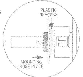
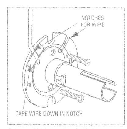
FIG. 8. INSTALLING INSIDE TRIM:
- Place Inside Rose Plate over spindle and on door with the two notches facing up.
- Insert Motor Wire through the Inside Rose plate and tape wire down in the notch to be sure the housing will not pinch or cut before fastening bolts.
- 3. Insert and fasten two mounting bolts.
IMPORTANT: The Motor Wire must come through either notch and lie within the notch without pinching or cutting the wire.
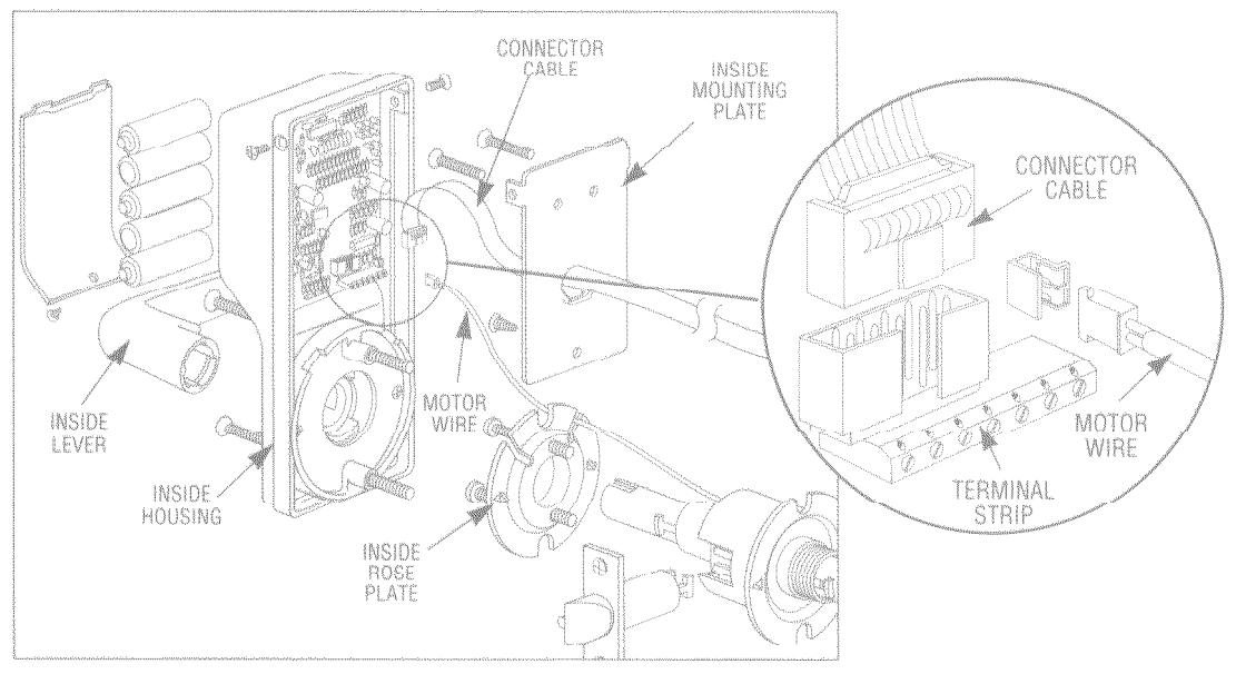
FIG. 9. INSTALLING INSIDE TRIM (Housing & Lever)
- Pull the Connector Cable through the Inside Mounting Plate. Position plate on door and fasten with two 8/32"x1" long F.H.M.S. Fasten wood screw at bottom.
- Plug the Connector Cable and the Motor Wire into the Housing. Note: The connectors fit only one way (do not force them in). See inset.
- Place Inside Housing over the inside spindle, making sure that all wires are inside of the housing before tightening the two thru bolts.
- 4 Place Inside Lever/Knob on spindle and push on
- until it engages with Lever/Knob Catch.Test lever/knob to be sure it is on securely and operates without binding.
- Fasten two 6/32" x 3/8"long F.H.M.S. on side of housing.
- Place 5 "AA" batteries into battery holder. IMPORTANT: Batteries must be in proper position (+) and (-) in order for lock to properly operate.
TEST LEVERS/KNOBS & CYLINDERS FOR PROPER OPERATION
Insert battery cover and fasten with 4-40 x 1/4" F.H.M.S. FOR PROGRAMMING, SEE PROGRAMMING INSTRUCTIONS.
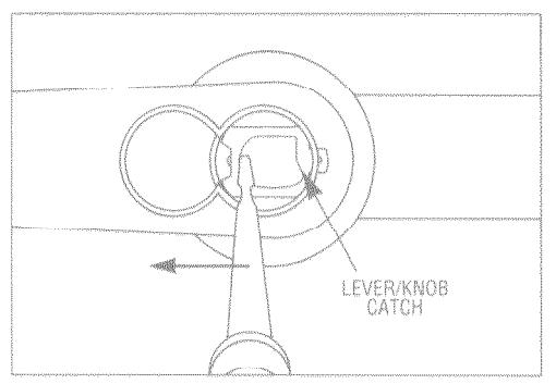
FIG. 10. TO REMOVE IC CORE LEVER/KNOB
1 With screwdriver inside lever/knob, push inside of Lever/Knob Catch to rear and pull off lever/knob.
TO INSERT IC CORE
- 2. Insert Alarm Lock tailpiece into cylinder.
- 3. With control key in cylinder turn clockwise.
- Insert cylinder into lever/knob and turn key counterclockwise to lock in position.
- 5. Remove control kev.
TO REMOVE CYLINDER, REVERSE PROCEDURE
For Handing and Door thickness, see Figs. 6 and 7.
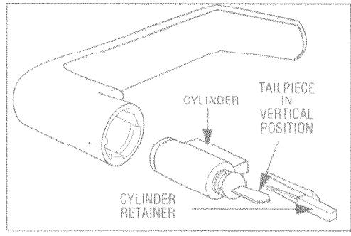
FIG. 11. CHANGING CYLINDER:
- 1. Remove outside lever/knob. See Fig. 6
- 2. Remove key from cylinder and pull plastic cylinder retainer from lever (using pliers), then remove cylinder.
TO REPLACE CYLINDER:
- 1. Tailpiece must be in vertical position in cylinder.
- 2. Insert cylinder in lever.
- 3. Press cylinder retainer into lever until flush with base of lever.
NOTE: USE TAILPIECE IN VERTICAL POSITION.
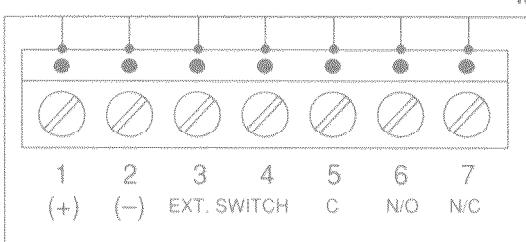
| FIG. | 12 | TERMINA | L BLOCK | FUNCTIONS | |
|---|---|---|---|---|---|
| *Section 1 | 2 | 3 | 4 | ||
| + | pppe | Remote | release | ||
| 100 | 6.7.7 | erri. |
Optional N/O D.C. Power Pushbutton Input 6 VDC or switch
C N/C N/C Remote output for monitoring or activation of external device
• 5-second changeover when correct code is entered
No additional power supply or electric strikes are required.
TROUBLESHOOTING
| ELECTRONIC TROUBLE | SOLUTION | ||
|---|---|---|---|
| Lock will open with or without entering code. | Check for proper insertion of Motor Connector. | ||
| Lock will not accept new codes during programming. | Remove batteries, hold down any button until lock resets, then install batteries and start programming again. | ||
| Lock drains batteries quickly. | Check all wires for pinching or cutting. Check for water damage. If condition persists, consult factory. | ||
| Lock is completely dead. | Check batteries for proper polarity and check for cut wires. | ||
| Lock emits steady tone when any button is pressed. | Low battery signal - replace batteries. | ||
| MECHANICAL TROUBLE | SOLUTION | ||
| Lever/knob pulls off. |
Lever/knob Catch not fully engaged. Lock is not centered on door.
Door too thick. |
||
| Unable to assemble outside lever. | Key and tailpiece orientation is incorrect. | ||
| Latch will not fully retract. | Lock is not properly engaged with latch or mis-aligned. Lock is not centered on door. | ||
| Key binds in lock. |
Lever/knob Catch not fully engaged. Lock is not centered on door.
Check for proper tailpiece and proper orientation of tailpiece. |
||

© 1996, Alarm Lock "Trilogy®" is a registered trademark of Alarm Lock "T2<sup>TM</sup>" and "T2 Trilogy<sup>TM</sup>" are trademarks of Alarm Lock