Alarm Lock DL1200ETNW, DL1300ETNW & PDL1300ETNW Mounting and Installation Instructions
Open the original PDF document
View PDF

345 Bayview Avenue Amityville, New York 11701 For Sales and Repairs 1-800-ALA-LOCK For Technical Service 1-800-645-9440
or visit us at http://tech.napcosecurity.com/ (Note: Technical Service is for security professionals only) Publicly traded on NASDAQ Symbol: NSSC
© ALARM LOCK 2018
DL1200ETNW - DL1300ETNW - PDL1300ETNW Networx Exit Trim Narrow Stile Access Locks MOUNTING AND INSTALLATION INSTRUCTIONS
WI2320LF 7/18
GENERAL DESCRIPTION
DL1200ETNW, DL1300ETNW The and PDL1300ETNW are keypad programmable or wirelessly programmable (through DL-Windows software) narrow stile entry trim for narrow stile aluminum doors. The following specialized templates are designed to utilize existing panic exit device mounting holes:
- Arrow<sup>™</sup> S1200/S1250 series (WI1758)
- Corbin Russwin<sup>®</sup> ED8200/ED8400 series (WI1759)
- DCI 1200/1300 series (WI1760)
- Dorma 5300 series (WI1761)
- Dor-O-Matic® 2090 series (WI1762)
- Jackson® 1095 series (WI1763)
- Von Duprin<sup>®</sup> 22 series (WI1764)
- Von Duprin<sup>®</sup> 33/35 series (WI1765)
All mounting hole locations shown on the above installation templates are referenced from the existing mounting holes of the previously installed panic exit device hardware.
When a valid User Code is entered, the DL1200ETNW, DL1300ETNW or PDL1300ETNW retracts a tailpiece, allowing the tailpiece to unlock the device when the lever is pressed down. PDL (proximity) models allow either a User Code or the presentation of a proximity card to unlock the device.
A User Code can be programmed to enable Passage Mode to allow unrestricted passage until another access code is entered, re-locking the trim. All locks are equipped with a mechanical metal key override. See WI2258 or WI2264 to enable Passage Mode and other programming features.
MECHANICAL FEATURES
The overall enclosure housing is 15-5/16" inches high, 1-5/8" inches deep and 1-3/4" inches wide. The trim is through-bolted to the stile of the door (using four #10 screws) and are secured on the interior side of the door. Supported stile thickness is 1-3/4".
- DL1300NW and PDL1300NW models support 5000 users and includes 36,000-event audit trail and 500 event schedule. Keypad or PC programmable
- Aluminum door retrofit outside trim for Arrow<sup>™</sup> S1200/ S1250 series, DCI 1200/1300 series, Corbin Russwin<sup>®</sup> ED8200/ED8400 series, 33/35 and 22 series, Dor-O-
- Matic® 2090 series, Jackson® 1095 series and Dorma 5300 series locks.
- All-metal, vandal-resistant 12-button keypad supports 3-6 digit PIN codes, and multilevel user hierarchy (master, manager, supervisor and basic users)
- Keypad or PC programmable (see model information). Quickly and easily add or delete users and enter "passage mode", service codes, group lock-out & group-enable
- PDL1300NW supports proximity ID cards, keyfobs and proximity tags with its integral proximity reader (high security applications can require use of both PIN code plus proximity credential for access)
- Real time clock and PC programmable automatic lock/ unlock scheduling for 500 events
- Wide weatherproof operating range from -31°F to 151°F (-35°C to 66°C)
- Provides 50,000 operations using 4AA batteries; includes audible and visual low battery alert
- Non-handed: fully field-reversible
- · Mechanical key override; interchangeable cores supported (Corbin/Russwin, Yale, Schlage, Medeco)
- Mortise Cylinder, 1-1/4" supplied (supports 1-1/8", 1-1/4", 1-3/8" and 1-1/3"
TABLE OF CONTENTS
| GENERAL DESCRIPTION1 | |
|---|---|
| MECHANICAL FEATURES1 | |
| MECHANICAL OVERRIDE CYLINDER CAMS2 | |
| CYLINDER COLLARS2 | |
| MOUNTING AND INSTALLATION3 | |
| INSTALL CYLINDER3 | |
| INSTALL THE LEVER4 | |
| PREPARE THE DOOR FOR "THROUGH-BOLTING"3 | |
| INSTALL TAILPIECE ON LOCK4 | |
| CONNECT BATTERIES4 | |
| INSTALL LOCK ON DOOR5 | |
| PROGRAMMING THE LOCK5 | |
| TEST DL LOCK OPERATION | |
| AFTER INSTALLATION6 | |
| NAPCO LIMITED WARRANTY8 |
MECHANICAL OVERRIDE CYLINDER CAMS
The DL1200ET and DL/PDL1300ET trim requires the use of an oval Alarm Lock cam (supplied with cylinder). For other manufacturers, please see the charts below.
| Cams for Standard Mortise Cylinders | ||
|---|---|---|
| Corbin-Russwin | HW1344 | |
| Marks | HW1346 | |
| Arrow | HW1348 | |
| Sargent | HW1348 | |
| Schlage | HW1349 | |
| Cams for IC Mortise Cylinders | ||
|---|---|---|
| Best* | HW1343 | |
| Corbin-Russwin | HW1345 | |
| Medeco | HW1347 | |
| Schlage | HW1350 | |
| Yale | HW1351 | |
| *Will be supplied together with Best IC Housing (HW1352) | ||
| Cylinder Length | Collar P/N |
|---|---|
| 1-3/8 | HW1331 |
| 1-½ | HW1342 |
CYLINDER COLLARS
The DL1200ETNW and DL/PDL1300ETNW can use a 1-1/8" & 1¼" mortise cylinder without the use of a collar (1¼" requires two plastic spacers, supplied). For cylinders longer than 1¼" a collar is required.
Order collars from an Alarm Lock distributor.
Cam for Mechanical Override Cylinder
IMPORTANT
Alarm Lock models DL1200ETNW , DL1300ETNW and PDL1300ETNW work with supported panic device models from Jackson , Dor-O-Matic , Von Duprin , Dorma , Arrow , DCI and Corbin .
However, the Dor-O-Matic 2090 and the Jackson 1095 require more than 85° of rotation to operate the latch, and therefore these models require use of the Alarm Lock DL1225ETNW , DL1250ETNW , DL/PDL1325ETNW or DL/PDL1350ETNW . These Alarm Lock models include either an oversized thumb-turn ( 1225ET and 1325ET series) or a knob ( 1250ET and 1350ET series) to permit the full 360° tailpiece
rotation required by the Dor-O-Matic 2090 and Jackson 1095 exit devices. Note: Tailpieces are sold separately and are specific to the exit trim used.
See the Alarm Lock Price Book at http:// tech.napcosecurity.com/ or your Alarm Lock dealer for a full list of supported exit device model numbers and corresponding tailpieces. Contact Alarm Lock sales at 1-800-ALA-LOCK for availability and lead times on these Networx models.
MOUNTING AND INSTALLATION Install Cylinder
1. Install Cylinder if not already installed at the factory. Screws A & B (see Fig. 1) are correctly set at factory. If it is difficult to screw in the cylinder, loosen the two screws near the actuator (A) one turn. If you find the cylinder is still difficult to screw in, then loosen the other screws (B) one turn. Do not loosen the screws all the way or it may be difficult to replace them properly! Note: The trim is manufactured to use a 1-1/8" or 1¼" Alarm Lock mortise cylinder with a HW-1302 cam. If the cylinder that will be used is longer than 1¼", a collar must be utilized. Please see the collar information on the previous page.
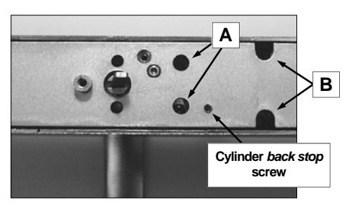
Fig. 1: Install Cylinder if not already installed at the factory
1a. Insert key half-way into the cylinder, then screw it in. See Fig. 1a. If cylinder will not seat flush, the cylinder back stop screw may require loosening. Cylinders that are longer than 1¼" will require a collar, which will stick out from the surface when correctly installed. Please see the cylinder information on the previous page.
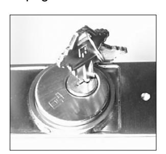
Fig. 1a: Insert key 1/2 way into cylinder and screw in
1b. After the cylinder is screwed in all the way, center the keyway toward the bottom (see Fig. 1b). If an interchangeable core cylinder is utilized, then center the interface toward the bottom. Tighten the screws that were loosened in step 1.
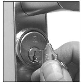
Fig. 1b: Center keyway toward bottom
1c. Remove the key. Use a 1/16" hex wrench to screw the cylinder back stop screw in fully. (See Fig. 1c) The key should now only rotate counterclockwise .
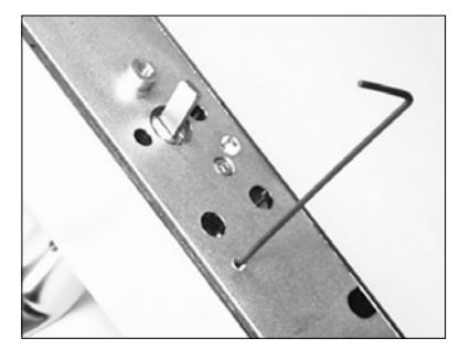
Fig. 1c: Use 1/16" hex wrench to screw in the cylinder back stop screw
NOTE: To remove cylinder, reverse steps 1a-1c.
Install the Lever
2. Install the lever with proper orientation for the lock/door hand used. Tighten the set screw using a 1/8" hex wrench (see Fig. 2).
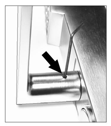
Fig. 2: Tighten lever set screw with 1/8" hex wrench
IMPORTANT! The top of the set screw must be at (or below) lever surface. If not, check to ensure the lever is fully pushed toward the trim.
Prepare the Door For "Through-Bolting"
- 3. Remove the existing panic/exit device to reveal its mounting hole locations. Place the template on the door, aligning the holes shown on the template (labeled "Existing Mounting Hole Locations") with the existing exit device mounting hole locations in the door. The template must also remain parallel to the edge of the door at all times . Reposition the template as often as needed until it is placed correctly.
- 3a. As labeled on the template, drill completely through the door for the four (4) 7/32" diameter throughbolt mounting holes and the 7/16" diameter battery cover access bolt hole.
- IMPORTANT!--Drill the holes STRAIGHT THROUGH the door, or the through-bolts will not
fit in the lock. THIS IS ESSENTIAL--drill slowly and STRAIGHT through the door.
Install Tailpiece on Lock
This lock operates a variety of exit device models; each exit device model requires a matching tailpiece be installed on the back of the lock. Install the tailpiece as follows:
4. Locate two 3/32" diameter cross holes in the Hub that protrudes from the back of the lock.
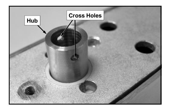
Fig. 4: The Hub on the back of the lock contains two 3/32" diameter holes.
4a. Remove the ½" long Roll Pin and Tailpiece from the tailpiece kit.
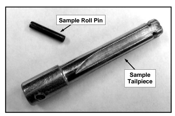
Fig. 4a: Sample Roll Pin and Sample Tailpiece.
4b. Insert the Roll Pin into one hole on the Hub as shown below (friction fit). At this time, do not drive the Roll Pin into the Hub further than the thickness of the Hub wall.
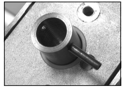
Fig. 4b: Insert Roll Pin into one Hub hole.
4c. Insert the Tailpiece shank into the Hub, aligning the Tailpiece cross hole with the Roll Pin.
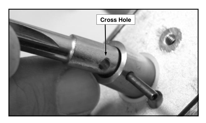
Fig. 4c: Align the Tailpiece cross hole with the Roll Pin.
4d. With a small hammer or wide jaw pliers, drive the Roll Pin through the Tailpiece cross hole and into the other Hub cross hole until both ends of the Roll Pin are flush with the outside of the Hub wall.
Connect Batteries
5. Loosen the #8-32 Phillips pan head screw located on the rear side of the base plate at the bottom of the lock (see Fig. 5). Turn counter-clockwise only until the battery cover slides off the housing (do not remove the screw completely).
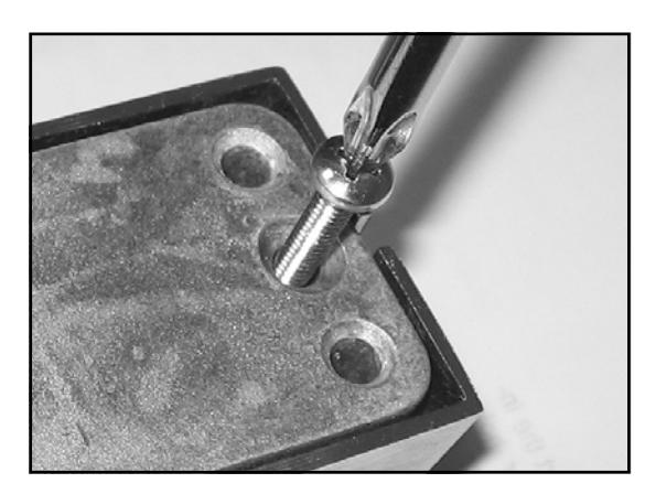
Fig. 5: The Phillips screw on the rear side locks or unlocks the battery cover. Do not remove screw .
5a. Plug in the battery connector. Leave the battery pack and connector outside the compartment.
Install Lock on Door
In order for the DL lock to operate properly, the Tailpiece must be installed in the correct position and engaged properly with the exit device hardware.
Once the lock is installed on the door, the correct position of the Tailpiece is difficult to determine--therefore the Tailpiece position must be adjusted prior to mounting. With the battery connector plugged in and the bat-
tery connector and battery pack outside its compartment, proceed as follows:
- 6. Stand the lock in the upright position.
- 6a. On the back of the DL lock, locate the Roll Pin that holds the Tailpiece to the Hub. Rotate the Hub/ Tailpiece assembly until the Roll Pin is in the horizontal position.
-
6b. At the lock keypad, enter a valid User Code
. For new locks, enter the default Master Code (use "12345" for the DL1200ETNW; use "123456" for the DL1300ETNW and PDL1300ETNW). Entering the Code engages the lock mechanism and draws the Hub into DL lock housing about 5/32".
- Immediately disconnect the battery plug , thus retaining the mechanism in the engaged ("fixed") position, unable to rotate. With the Tailpiece now unable to rotate freely, the remaining steps can be performed more easily.
- 6c. Look down the length of the Tailpiece to observe its "front view". Verify that the cross-shaped Tailpiece is in the vertical and horizontal position (+) and the Tailpiece can only rotate when the lever is turned. If the Tailpiece is not correctly positioned, manually rotate the Tailpiece until it "clicks" into the engaged position and is unable to rotate.
- 6d. Apply a film of oil to the front of the Tailpiece. Place the DL lock on the door, inserting the Tailpiece into the "Receiver" (or "keyway") of the existing exit device. Verify the shaft of the Tailpiece floats inside the exit device Receiver (the Tailpiece must move in and out of the Receiver freely).
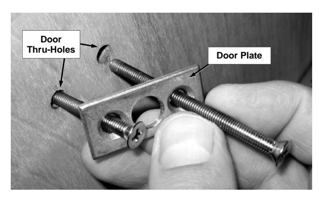
Fig. 6e: Insert mounting screws into Door Plate holes, then into the inside door thru-holes.
6e. Secure the DL lock to the door with four (4) through-door mounting screws and two Door Plates as follows: Insert a mounting screw into one of the two Door Plate holes. Inside the door, insert the mounting screw into the door thru-holes, carefully threading the mounting screw into the DL lock housing by hand (see Fig. 6e). Repeat for three remaining mounting screws. Snug all four mounting screws before final tightening--do not over-tighten.
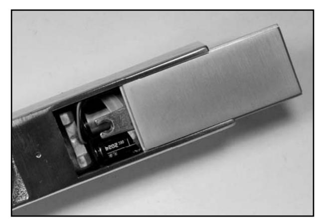
Fig. 6f: Install the battery pack: Push all wires inside the battery compartment and slide plate back on.
6f. Plug in the battery connector and insert the battery pack into the battery compartment. Neatly push all wiring inside the compartment. Holding battery in place , slide cover back on. Secure the battery cover by tightening the #8-32 Phillips pan head screw located on the rear side of the base plate (access this screw from the 7/16" thru-hole drilled in the door in step 3a). Do not over tighten the screw . Upon connecting the battery power, the DL lock disengages.
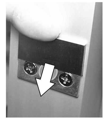
Fig. 6g: Slide down to install decorative plate covers
6g. Install the decorative Door Plate Covers by sliding them--in a vertical direction from top to bottom--over the installed Door Plates.
Programming the Lock
Refer to programming instructions (WI2258 or WI2264) for specific instructions for "First Time Startup" and "Change Factory Master Code" before connecting the battery.
The lock must be powered up correctly (and have its factory Master Code changed) or erratic lock behavior can result.
TEST DL LOCK OPERATION AFTER INSTALLATION
Before testing, be sure the lock has been powered up using the specific "Power Up" instructions detailed in the WI2258 or WI2264 programming instructions.
1. With the key removed, the lever (or turnpiece) must be able rotate without retracting the latch, thus signifying the DL lock is disengaged.
Test Step 1
2. At the keypad, enter a valid the User Code. For new locks, enter the default Master Code ("12345" for the DL1200ETNW; "123456" for the DL1300ETNW and PDL1300ETNW).
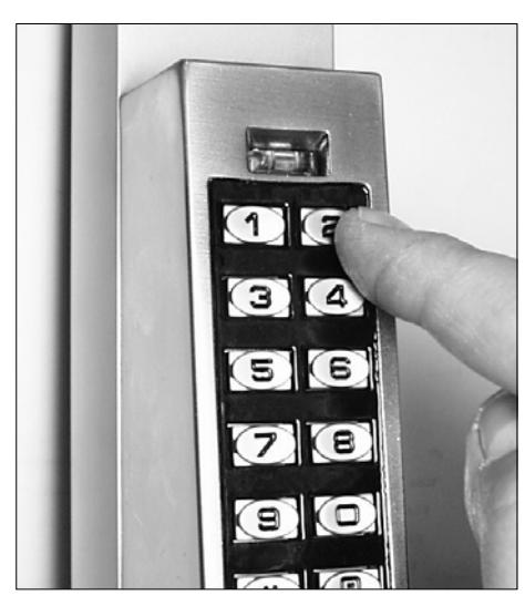
Test Step 2
- For each number key pressed, verify the red LED illuminates.
- When the last number of the Code is pressed, verify the green LED turns on continuously for several seconds as you listen for the mechanism engage.
- When the Code times out, verify the red LED flashes as the mechanism disengages. Note: When disengaged, verify the lever (or "turnpiece") can be rotated
without any movement to the latch.
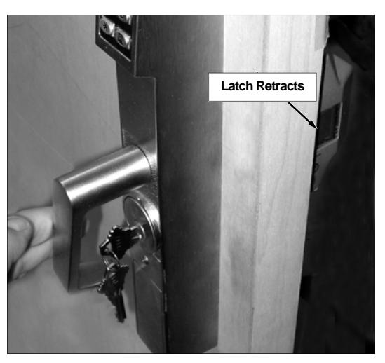
- At the keypad, re-enter the Code. After the last digit of the Code is pressed and the lock engages, rotate the lever or turnpiece. Verify the latch on the exit device retracts. When the Code times out, the red LED flashes and the mechanism disengages.
- 3. Test the key: Insert the metal key, turn counterclockwise and operate the lever or turnpiece. Verify the latch retracts.
Test Step 3
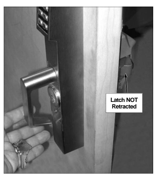
4. Turn the key clockwise and remove. Verify the latch does NOT retract when the lever or turnpiece is rotated.
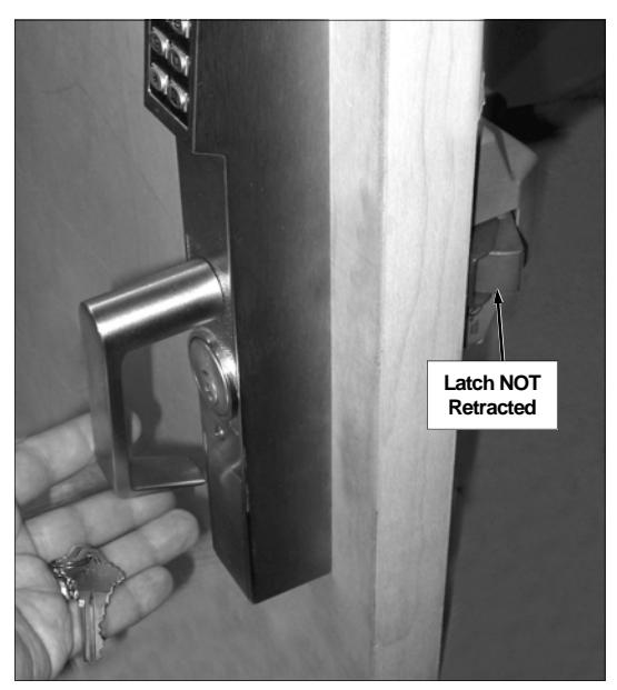
Test Step 4
NOTES
ALARM LOCK LIMITED WARRANTY
ALARM LOCK SYSTEMS, INC. (ALARM LOCK) warrants its products to be free from manufacturing defects in materials and workmanship for twenty four months following the date of manufacture. ALARM LOCK will, within said period, at its option, repair or replace any product failing to operate correctly without charge to the original purchaser or user.
This warranty shall not apply to any equipment, or any part thereof, which has been repaired by others, improperly installed, improperly used, abused, altered, damaged, subjected to acts of God, or on which any serial numbers have been altered, defaced or removed. Seller will not be responsible for any dismantling or reinstallation charges, environmental wear and tear, normal maintenance expenses, or shipping and freight expenses required to return products to ALARM LOCK. Additionally, this warranty shall not cover scratches, abrasions or deterioration due to the use of paints, solvents or other chemicals.
THERE ARE NO WARRANTIES, EXPRESS OR IM-PLIED, WHICH EXTEND BEYOND THE DESCRIPTION ON THE FACE HEREOF. THERE IS NO EXPRESS OR IMPLIED WARRANTY OF MERCHANTABILITY OR A WARRANTY OF FITNESS FOR A PARTICULAR PUR-POSE. ADDITIONALLY, THIS WARRANTY IS IN LIEU OF ALL OTHER OBLIGATIONS OR LIABILITIES ON THE PART OF ALARM LOCK.
Any action for breach of warranty, including but not limited to any implied warranty of merchantability, must be brought within the six months following the end of the warranty period.
IN NO CASE SHALL ALARM LOCK BE LIABLE TO ANY-ONE FOR ANY CONSEQUENTIAL OR INCIDENTAL DAMAGES FOR BREACH OF THIS OR ANY OTHER WARRANTY, EXPRESS OR IMPLIED, EVEN IF THE LOSS OR DAMAGE IS CAUSED BY THE SELLER'S OWN NEGLIGENCE OR FAULT.
In case of defect, contact the security professional who installed and maintains your security system. In order to exercise the warranty, the product must be returned by the security professional, shipping costs prepaid and insured to ALARM LOCK. After repair or replacement, ALARM LOCK assumes the cost of returning products under warranty. ALARM LOCK shall have no obligation under this warranty, or otherwise, if the product has been repaired by others, improperly installed, improperly used, abused, altered, damaged, subjected to accident, nuisance, flood, fire or acts of God, or on which any serial numbers have been altered, defaced or removed. ALARM LOCK will not be responsible for any dismantling, reassembly or reinstallation charges, environmental wear and tear, normal maintenance expenses, or shipping and freight expenses required to return products to ALARM LOCK. Additionally, this warranty shall not cover scratches, abrasions or deterioration due to the use of paints, solvents or other chemicals.
This warranty contains the entire warranty. It is the sole warranty and any prior agreements or representations, whether oral or written, are either merged herein or are expressly cancelled. ALARM LOCK neither assumes, nor authorizes any other person purporting to act on its behalf to modify, to change, or to assume for it, any other warranty or liability concerning its products.
In no event shall ALARM LOCK be liable for an amount in excess of ALARM LOCK's original selling price of the product, for any loss or damage, whether direct, indirect, incidental, consequential, or otherwise arising out of any failure of the product. Seller's warranty, as hereinabove set forth, shall not be enlarged, diminished or affected by and no obligation or liability shall arise or grow out of Seller's rendering of technical advice or service in connection with Buyer's order of the goods furnished hereunder.
ALARM LOCK RECOMMENDS THAT THE ENTIRE SYS-TEM BE COMPLETELY TESTED WEEKLY.
Warning: Despite frequent testing, and due to, but not limited to, any or all of the following; criminal tampering, electrical or communications disruption, it is possible for the system to fail to perform as expected. ALARM LOCK does not represent that the product/system may not be compromised or circumvented; or that the product or system will prevent any personal injury or property loss by burglary, robbery, fire or otherwise; nor that the product or system will in all cases provide adequate warning or protection. A properly installed and maintained alarm may only reduce risk of burglary, robbery, fire or otherwise but it is not insurance or a guarantee that these events will not occur. CONSEQUENTLY, SELLER SHALL HAVE NO LIA-BILITY FOR ANY PERSONAL INJURY, PROPERTY DAMAGE, OR OTHER LOSS BASED ON A CLAIM THE PRODUCT FAILED TO GIVE WARNING. Therefore, the installer should in turn advise the consumer to take any and all precautions for his or her safety including, but not limited to, fleeing the premises and calling police or fire department, in order to mitigate the possibilities of harm and/or damage.
ALARM LOCK is not an insurer of either the property or safety of the user's family or employees, and limits its liability for any loss or damage including incidental or consequential damages to ALARM LOCK's original selling price of the product regardless of the cause of such loss or damage.
Some states do not allow limitations on how long an implied warranty lasts or do not allow the exclusion or limitation of incidental or consequential damages, or differentiate in their treatment of limitations of liability for ordinary or gross negligence, so the above limitations or exclusions may not apply to you. This Warranty gives you specific legal rights and you may also have other rights which vary from state to state.