Alarm Lock DL And PDL Series Installation Instructions For All Cylindrical Type Locksets (2 1-8inch Bore)
Open the original PDF document
View PDF| T R O U B L | E S H O O T I N G |
|---|---|
| ELECTRONIC TROUBLE | SOLUTION |
| Locks works in reverse. | Reverse motor wires in connector. |
| Lock will not accept new codes during programming. | Disconnect battery connector, hold down any button until lock resets, then reconnect and start programming again. |
| Lock drains batteries quickly. | Check all wires for pinching or cutting. Check for water damage. If condition persists, consult factory. |
| Lock is inoperative. | Check batteries for proper polarity and check for cut wires. |
| Lock produces high pitch steady tone during lock operation. | Low battery signal - replace batteries. |
| MECHANICAL TROUBLE | SOLUTION |
| Lever/knob pulls off. | Lever/knob Catch not fully engaged. Lock is not centered on door. Door too thick. (See page 6, Fig.7) |
| Unable to assemble outside lever. | Key and tailpiece orientation is incorrect. (See page 9, Fig.13 & 14) |
| Latch will not fully retract. | Lock is not properly engaged with latch or mis-aligned. Lock is not centered on door. (See page 6, Fig.6) |
| Key binds in lock. | Lever/knob Catch not fully engaged. Lock is not centered on door. Check for proper tailpiece and proper orientation of tailpiece. (See page 9, Fig.13 & 14) |
TECH SUPPORT: 1-800-ALA-LOCK
ALARM LOCK SYSTEMS, INC. is a division of the NAPCO Security Group 345 Bayview Avenue, Amityville, NY 11701 (631) 789-4871 1-800-252-5625 Fax: (631) 789-3383
© 1996, Alarm Lock "Trilogy®" is a registered trademark of Alarm Lock "T2™" and "T2 Trilogy™" are trademarks of Alarm Lock
Part No. WI 949D 10/00
DL AND PDL SERIES INSTALLATION INSTRUCTIONS


ELECTRONI ELOCKSETS

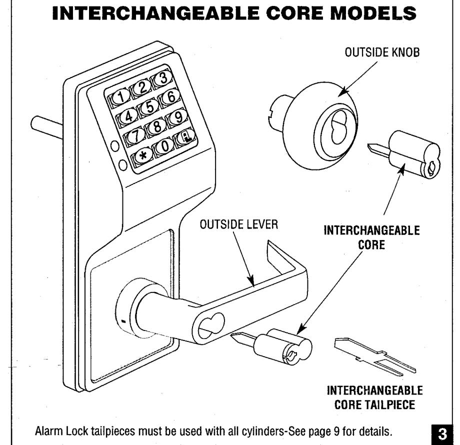

FIG. 1 DOOR PREPARATION:
- 1. Fold and place template on high edge of door at the recommended height from floor.
- 2. Mark hole centers on door and door edge.
- 3. Drill 3/8" Thru-Bolt holes first, then drill 2-1/8" hole.
FOR HARDWOOD DOORS:
Notch on both sides of 2-1/8" hole to accommodate mounting plate tabs.
FOR HOLLOW METAL DOORS require horizontal and vertical lock and latch case support. Provided by door manufacturer.

FIG. 2 ALARM LOCK INSTALLATION JIG
- 1. If 2-1/8" hole exists, use optional Alarm Lock Installation Jig to insure accurate locating and drilling of 3/8" and 5/16" Thru-Bolt holes.
- 2. For best results, align the Installation Jig to door with a square and clamp to door before drilling.

FIG. 3 LATCH INSTALLATION:
Drill 1" diameter hole for latch. Mortise for latch front. Insert latch and fasten with two screws supplied.
NOTE: It is important that both 1" and 2-1/8" holes be on the same horizontal center line

FIG. 4 STRIKE INSTALLATION:
- 1. Align strike with latch.
- 2. Trace strike outline on door jamb.
- 3. Mortise jamb and install dust box and strike
PREPARING LOCK FOR INSTALLATION:
- Insert the Lever/Knob Catch Pin into hole in the inside housing, depress Lever/Knob Catch and pull off lever/knob.
- 2. With the same pin depress the Lever/Knob catch again to remove the inside housing.

FIG. 5 INSTALLING OUTSIDE TRIM ASSEMBLY (Lever/knob, Housing & Lock body)
1. With inside lever/knob and housing removed insert Motor wire through 2-1/8" hole and the other wires through the 3/4" hole.
5
Insert Outside trim assembly into door and be sure to properly engage the lock body with the latch. See Page 6, Fig. 6 "View from inside of door" diagram.

FIG. 6 VIEW FROM INSIDE OF DOOR:
1. Latch Yoke must engage lock housing and tailpiece must engage Retractor.

FIG. 7 HOW TO ADJUST DOOR THICKNESS:
Locks are factory assembled for 1-3/4" thick doors using 3 plastic spacers. FOR OTHER DOOR THICKNESS:
- Remove outside lever/knob. outside housing and unscrew outside rose plate.
- 2a FOR 1-5/8" DOOR remove one plastic spacer.
- 2b.FOR 1-78" DOOR add one plastic spacer.
- 3. Screw mounting rose plate up to
- Reassemble housing and lever/knob.
FOR OTHER DOOR THICKNESS CONSULT FACTORY
ALL LOCKS COME PREASSEMBLED FOR RIGHT HAND (RIGHT HAND REVERSE).
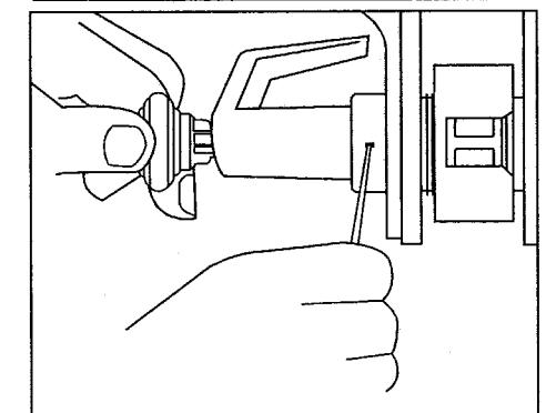
FIG. 8 TO REVERSE HANDING-LEVERS:
With the inside Lever and Housing off:
- Insert kev into outside cylinder & turn clockwise 45°, depress Lever/Knob Catch and pull lever off.
- 2. Rotate lock body 180° with the outside spindle. Be sure lever/knob catch faces the door edge. If necessary depress Lever/ Knob Catch in order to rotate outside spindle 180°.
- 3. With key in cylinder at 45° clockwise, position lever on spindle and press on until lever/knob catch engages. Remove key and test lever for proper engagement by turning and pulling.
FOR IC CORE MODELS SEE PAGE 9
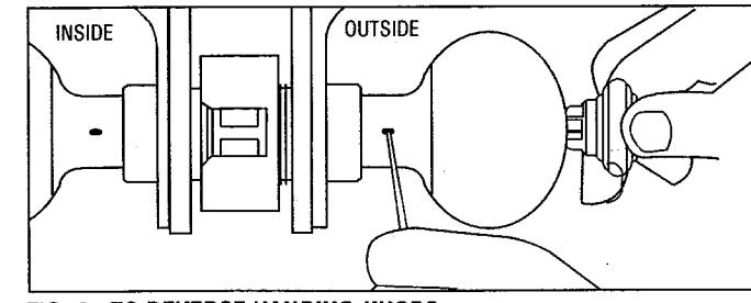
FIG. 9a TO REVERSE HANDING-KNOBS:
With the inside Knob and Housing off:
- 1. Insert key into outside cylinder & turn clockwise 45°, depress Lever/Knob Catch & pull knob off.
- 2. Rotate lock body with the outside spindle 180°. Be sure lever/knob catch faces the door edge. If necessary depress Lever/Knob Catch in order to rotate outside spindle 180°.
- 3. With key 1/2 way in cylinder place knob on spindle. Wiggle key to obtain proper alignment. Be sure to push knob straight on up to lever/knob catch.
(See FIG.9b)
- 4. Insert key fully and turn clockwise, then depress lever/knob catch and push knob until lever/ knob catch engages. Widdle knob if necessary for proper engagement.
- 5. Remove key and test knob for proper engagement by turning and pulling.
FOR IC CORE MODELS SEE PAGE 9

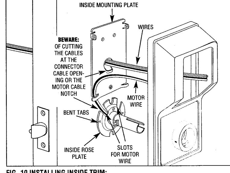
FIG. 10 INSTALLING INSIDE TRIM:
- 1. Place inside Rose Plate over spindle and on door with the two slots facing up and the bent tabs facing door. Fasten with two 1" long pan headed screws. IMPORTANT: The Motor Wire must come through either slot and lie within the notch without pinching or cutting the wire.
- 2. Position inside mounting plate and pull all connectors and cables through the mounting plate opening without pinching or cutting the cables. Fasten with flat head screws. Pull the Connector cable to be sure housing or cable opening does not pinch or cut wire before fastening bolts.
- 3. Place inside housing over the spindle making sure that all wires are through the housing before tightening the two bolts

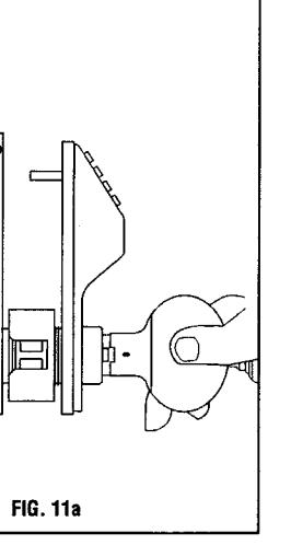
FIG. 11 INSTALLING INSIDE TRIM: (Housing & Jever/knob)
1. Connect the Battery and Motor connectors.
Note the connectors fit only one way (do not force them). See inset. Seal the connectors with Dielectric Grease included.
- 2. Place battery pack & loose wires inside housing.
- 3. Place battery pack cover on and fasten w/screw.
FOR LEVERS:
4a. Place Inside lever on spindle and push until it engages with Lever Catch. Test lever to be sure it is on securely and operates without binding. FOR KNOBS:
4b.Place Inside knob on spindle and push up against the Knob Catch, (Fig.11a) depress Knob Catch and push knob until it engages. Test knob by turning and pulling to be sure it is on securely and operates without binding.
FOR KNOBS AND LEVERS:
5. Fasten two side screws on side of housing then insert the 2 Thru-bolts.
6. Insert battery cover & fasten with screw.
TEST LOCKSET FOR PROPER OPERATION BEFORE CLOSING DOOR
FOR PROGRAMMING SEE SEPARATE PROGRAMMING INSTRUCTIONS.

FIG. 12. TO REMOVE IC CORE LEVER/KNOB
1. With screwdriver inside lever/knob, push inside of Lever/Knob Catch to rear and pull off lever/knob
TO INSERT IC CORE
- 2. Insert Alarm Lock tailpiece with washer into cylinder.
- 3. With control key in cylinder turn clockwise.
- 4. Insert cylinder into lever/knob and turn key counterclockwise to lock in position.
- Remove control key.
TO REMOVE CYLINDER REVERSE PROCEDURE
For Handing & Door thickness see Page 6, Fig. 7.
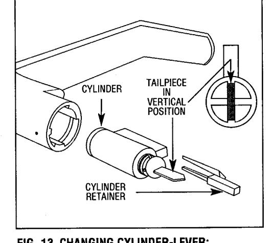
FIG. 13 CHANGING CYLINDER-LEVER:
- 1. Remove outside lever. See Page 6, Fig. 8.
- 2. Remove key from cylinder and pull plastic cylinder retainer from lever (using pliers). then remove cylinder.
TO REPLACE CYLINDER-LEVER:
- 1. Tailpiece must be in vertical position in cylinder.
- 2. Insert cylinder in lever.
- 3. Press cylinder retainer into lever until flush with base of lever.
NOTE: FOR LEVERS USE TAILPIECE IN VERTICAL POSITION.
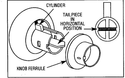
FIG. 14 CHANGING CYLINDER-KNOB:
- 1. Remove outside knob. See Page 7, Fig. 9a.
- 2. Remove key from cylinder.
- 3. Pull knob ferrule off of knob.
- 4. Remove cylinder from knob.
TO REPLACE CYLINDER-KNOB:
- 1. Place cylinder into knob with tailpiece in horizontal position.
- 2. Place ferrule on knob with bent tab facing front of lock and press on.
- 3. Press cylinder retainer into lever until flush with base of lever.
NOTE: FOR KNOBS USE TAILPIECE IN HORIZONTAL POSITION.


#HW620


REPLACEMENT STANDARD TAILPIECE FOR ALARM LORI AND ILCO LOCK TAILPIECE #HW597 Washer #WA160 Washer #WA160

REPLACEMENT TAILPIECE FOR SCHLAGE #HW580

IC CORE FOR USE WITH BEST, ARROW, FALCON, MEDICO-MARK, KSP #HW598 Washer #WA160
FIG. 15. TO INSTALL INTERCHANGEABLE CORE
- 1. Insert control key in core and turn clockwise.
- 2. Insert tailpiece in core.
- 3. With control key in core, insert core fully into lock.
- 4. Turn key counterclockwise and remove key.
TO REMOVE IC CORE-ALL FUNCTIONS:
1. Insert control key and turn clockwise, then pull on key to remove core.


FIG. 17. JUMPER
Mode 1: No relay function (Factory default).
TO INSTALL JUMPER: Remove Mounting Plate. Install Jumper. Replace Plate.
Mode 2: Relay change over when correct code is entered.
Mode 3: Relay change over when any button is pressed.