Alarm Lock Cylinder Adapter Kit Installation Instructions
Open the original PDF document
View PDF

Bayview Avenue, Amityville, New York 11701 For Sales and Repairs 1-800-ALA-LOCK For Technical Service 1-800-645-9440
Cylinder Adapter Kits Installation Guide
WI1163FLF 10/19
or visit us at <a href="http://tech.napcosecurity.com/">http://tech.napcosecurity.com/</a> (Note: Technical Service is for security professionals only) Publicly traded on NASDAQ Symbol: NSSC © ALARM LOCK 2019
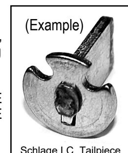
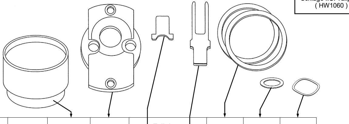
To replace a specific cylinder, a specific Cylinder Adapter Kit is required. The kit includes: Cylinder Collars, Cylinder Adapter, IC or Standard Tailpiece, Plastic Rings, mounting screws, Washer and Wave Washer. Kit does NOT include the cylinder. Note: When ordering kit, specify the finish at the end of the Part #. For example, ET-ARIC/US3.
ATTENTION: WHEN INSTALLING THE ADAPTER KIT, BE SURE TO REPLACE THE ORIGINAL TAILPIECE WITH THE TAILPIECE INCLUDED IN THE KIT. IN ADDITION, BE SURE TO REPLACE ANY GREASE THAT WAS REMOVED DURING THE INSTALLATION.
| Kit Description | Part # |
Cylinder
Collar(s) |
Cylinder
Adapter |
| Tailpiece | | Plastic | Washer | Wave | |
|---|---|---|---|---|---|---|---|---|
| Std | IC | Rings | Washer | Washer | ||||
| Arrow 6 & 7 pin I.C. | ET-ARIC |
HW1098
HW1077 |
HW1066 | HW1062 | HW1099 | WA200 | ||
| Arrow Standard | ET-AR | HW980 | HW1066 | HW1053 | HW1099 | WA200 | ||
| Assa Standard | ET-AS | HW980 | HW1069 | HW1054 | HW1099 | WA200 | ||
| Alarm Lock Standard | ET-AL | HW980 | HW1007 | HW971 | HW573 | WA200 | ||
| BEST 6 & 7 PIN I.C. | ET-BIC |
HW1098
HW1077 |
HW1065 | HW1062 | HW1099 | WA200 | ||
| Corbin I.C. | ET-CIC | HW980 | HW1067 | HW1061 | HW1099 | WA200 | ||
| Corbin Standard | ET-C | HW1077 | HW1067 | HW1055 | WA200 | |||
| Medico 6 & 7 Pin I.C. | ET-MIC | HW1051 | HW1063 | HW971 | HW1099 | WA171 | WA200 | |
| Medico Standard | ET-M | HW1051 | HW1069 | HW1056 | HW1099 | WA200 | ||
|
Sargent I.C. Small / Large
Format Core |
ET-RIC |
HW2145
HW1051 |
HW1066 | HW1080 | HW1099 | WA200 | ||
| Sargent Standard | ET-R | HW980 | HW1066 | HW971 | HW1099 | WA200 | ||
| Schlage I.C. | ET-SIC | HW1098 | HW1063 |
HW1060
(see image above) |
HW1099 | HW830 | WA200 | |
| Schlage Standard | ET-S | HW980 | HW1007 | HW1057 | WA200 | |||
| Yale 6 & 7 Pin I.C. | ET-YIC |
HW1098
HW1151 |
HW1063 | HW1059 | HW573 | WA160 | WA200 | |
| Yale Standard | ET-Y | HW1077 | HW1063 | HW1058 | WA200 | |||
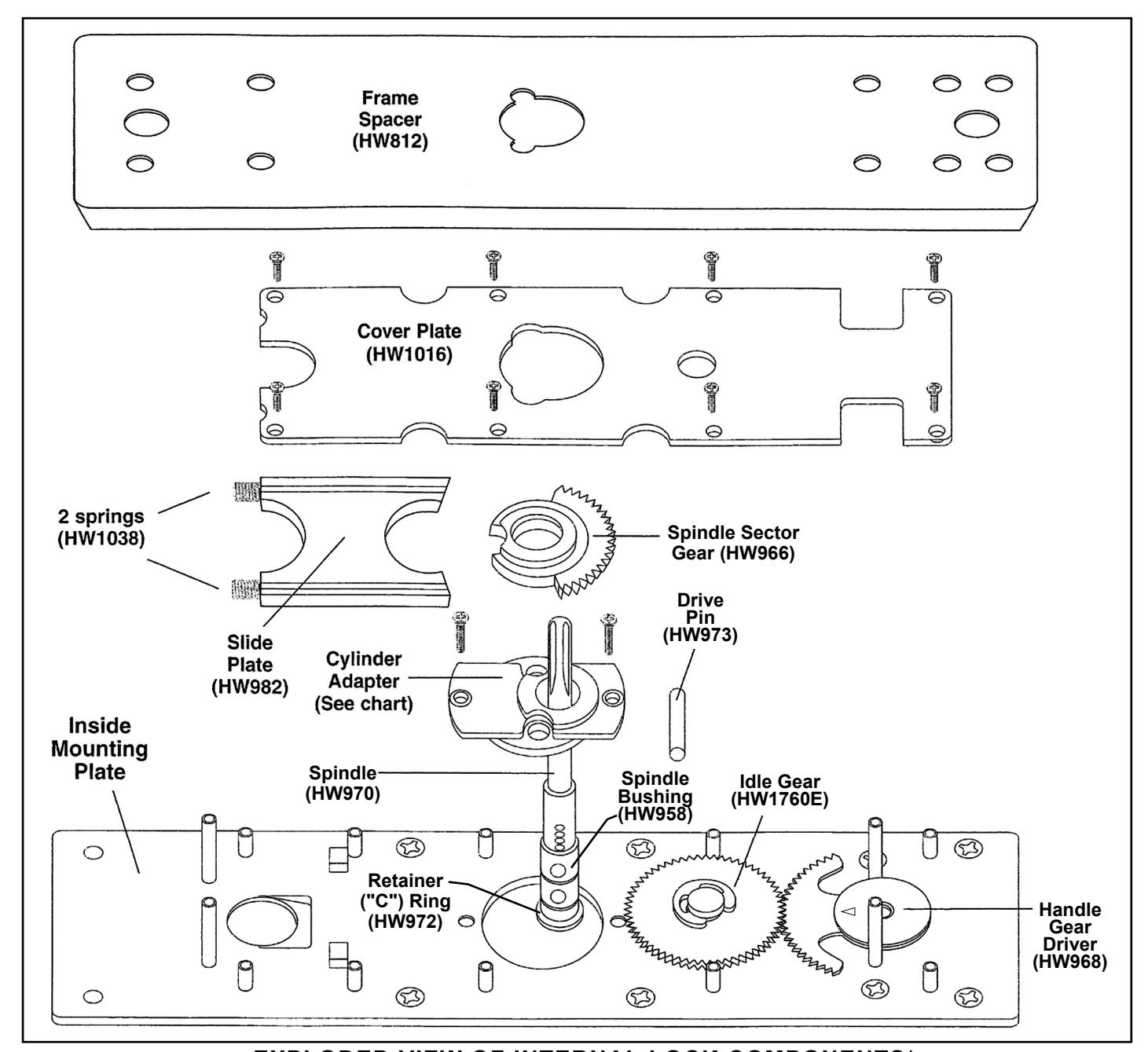
EXPLODED VIEW OF INTERNAL LOCK COMPONENTS*
*Alarm Lock Limited Warranty is printed in the original installation instructions (available for download at <a href="http://tech.napcosecurity.com/">http://tech.napcosecurity.com/</a>)
TO REPLACE THE CYLINDER ADAPTER:
1. Remove the Frame Spacer.
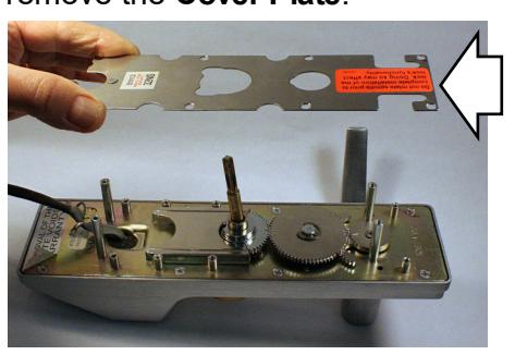
2. Remove screws necessary to unfasten and remove the Cover Plate .
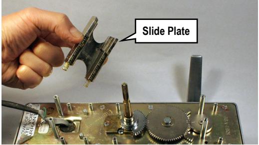
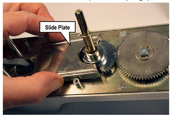
3. Remove Slide Plate (Careful! 2 springs may pop out).
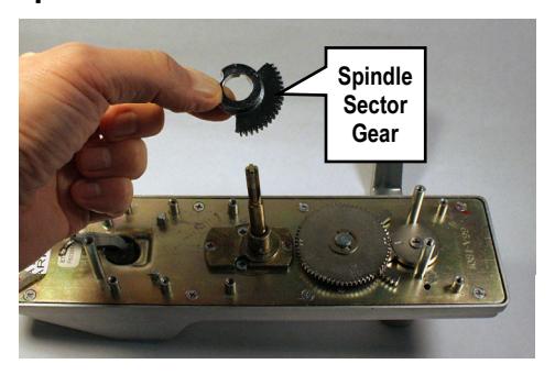
4. Use screwdriver to carefully pry up and remove Spindle Sector Gear .
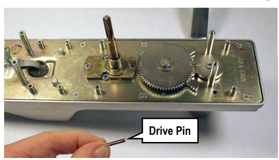
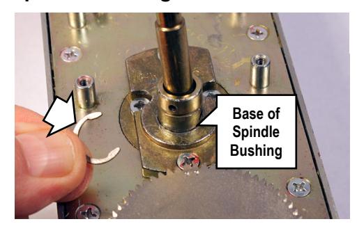
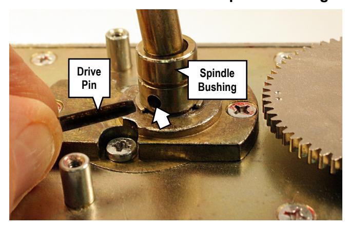
5. Remove Drive Pin from Spindle Bushing .
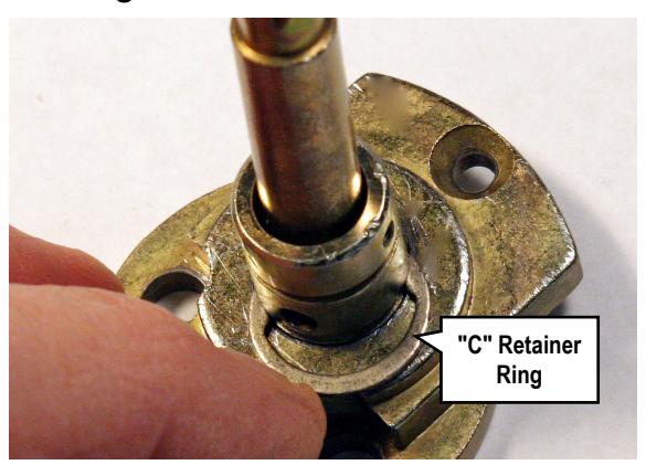
6. Remove the "C" Retainer Ring from the base of the Spindle Bushing .
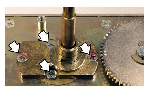
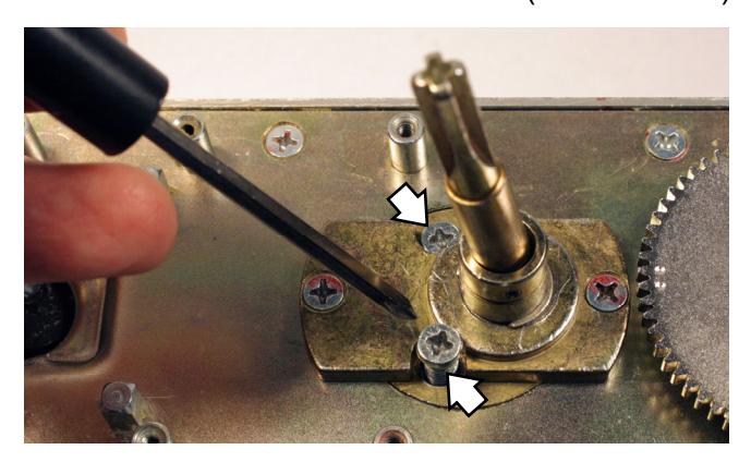
7. Remove four screws: Two screws to disengage the Cylinder Adapter , and two screws to detach the factory cylinder.
8. Push the Spindle / Spindle Bushing assembly out of the factory Cylinder Adapter to separate.
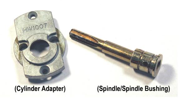
Set aside the factory Cylinder Adapter , factory Cylinder Collar and the factory cylinder. Install the new cylinder using all necessary parts included in the Cylinder Adapter Kit (see chart on page 1), as follows:
New Cylinder Installation
8. Insert the Spindle / Spindle Bushing assembly into the bottom of the new Cylinder Adapter . Re-install the "C" Retainer Ring into the base of the Spindle Bushing to secure.
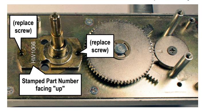
9. Position the Cylinder Adapter with its stamped part number facing "up" towards the top of the lock. Secure with its two small screws removed previously.
Hint: Before re-installing the Drive Pin , prepare and install the new cylinder.
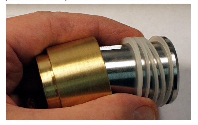
10. Prepare the new cylinder:
Insert the new cylinder into the new Cylinder Collar , using as many Plastic Rings as necessary to ensure that the face of the cylinder is flush with (or
slightly below) the Cylinder Collar . Install the new tailpiece, if needed (see chart). (IC core shown)
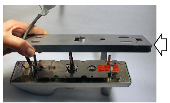
Install this cylinder assembly into the front of the lock and secure with its two screws (shown below).
Note: Remember, the Cylinder Collar should be snug, but remain free to turn (its ability to turn is a security feature). If necessary, use a Wave Washer to ensure the Cylinder Collar is not wobbly or rattling.
11. Re-install the Drive Pin into the Spindle Bushing .
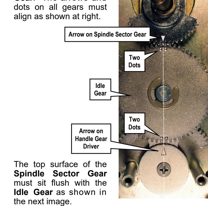
12. Before installing the Spindle Sector Gear , be sure the two dots on the Idle Gear and the arrow on the Handle Gear Driver are precisely aligned as shown in the photo shown below. If mis-aligned, simply remove the "C" retainer ring on the Idle Gear and re-align the gear teeth.
Re-install the Spindle Sector Gear . The gear tooth with the arrow must be placed between the two dots on the Idle Gear . The arrows and dots on all gears must align as shown at right.
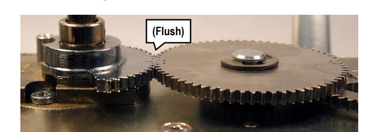
After the gear teeth are aligned and meshed, gently tap with a small hammer, if necessary, until flush.
13. Re-install the Slide Plate (with its 2 springs).
14. Re-install and secure the Cover Plate and the Frame Spacer (see exploded view illustration and steps 2 and 1) using the screws removed earlier.