Alarm Lock ArchiTech by Networx User’s Guide
Open the original PDF document
View PDF

ArchiTech™ by Networx™ USER'S GUIDE
© NAPCO Security Technologies, Inc. 2016 OI385B 09/16
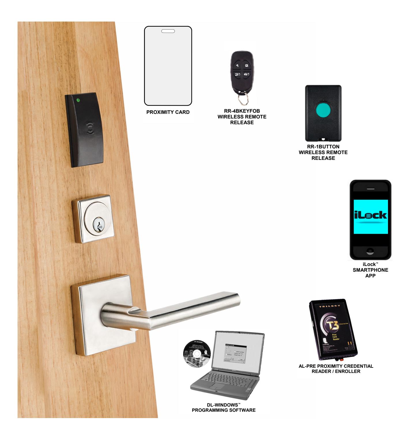
ArchiTech™ by Networx™ Wireless Network Access Control System with Proximity Access
ArchiTech™ by Networx™ Wireless Locks
THE ARCHITECH BY NETWORX WIRELESS ACCESS CONTROL SYSTEM IS A STATE-OF-THE-ART MICROPROCESSOR-BASED COMPUTER NETWORK PROGRAMMABLE PROXIMITY SECURITY LOCK.
ArchiTech™ Series Locks are an ideal access control solution, blending the advanced and robust Networx™ wireless access control system with the classic mortise lock functionality where a simple button press allows for the lock to remain in passage. ArchiTech Series Locks can be used to control access a door at a time; across a wireless network; or as an integral part of a new or existing security system—spanning a few, or hundreds of doors, in one building, a campus or multiple sites around the world.
ArchiTech security locks are designed to allow all features to be programmed through its wireless Networx radio link from a DL-Windows-equipped computer. With "wireless" communication, physical cables are NOT required to transfer data between DL-Windows and the wireless locks. A Networx Gateway is used in conjunction with your computer to retrieve logs, download User credentials and program features into each wireless lock in the system. In addition, its real-time clock / calendar automatically adjusts for Daylight Saving Time and allows for automated programming of scheduled events.
Table of Contents
| About this Manual 2 |
|---|
| ArchiTech Wireless Lock Features 3 |
| Supported Products and Applications 4 |
| Terminology Used in this Manual 5-6 |
| ArchiTech Series Design Overview 7-8 |
| ArchiTech Series Battery Life Maximization 8 |
| ArchiTech Series Startup Procedure 9 |
| "Stand-Alone Mode" Operation 10 |
| Manual Card Enrollment 10 |
| "DL-Windows Mode" Re-Activation 10 |
| "DL-Windows Mode" Operation / Features 11-13 |
| Emergency Commands 14-15 |
| Bluetooth Support 16 | |
|---|---|
| Using the iLock App 17-18 | |
| Wireless Remote Releases 19 | |
| Low Battery and Battery Replacement 20 | |
| Erase All Programming 21 | |
| Power Down Retain Existing Programming 22 | |
| LED and Sounder Indications 23 | |
| ArchiTech User Number Definitions 24 | |
| User Card Record Sheets 25-27 | |
| Glossary 28-29 | |
| ArchiTech Networx Limited Warranty 32 |
About this Manual
This manual documents the programming, operation and features of the ArchiTech™ by Networx™ series wireless locks. If you are new to DL-Windows, this manual does not contain preliminary information regarding integration with DL-Windows; stop here, read the DL-Windows User's Guide (OI382) and the DL-Windows for Networx User's Guide (OI383) to become familiar with DL-Windows, then return here. Some terms you will encounter include:
- The word " lock " is a generic word used to indicate one of the many ArchiTech™ by Networx physical locking device models available. This physical lock may be in its normally "locked" state (preventing passage through the door) or in an "unlocked" state (allowing passage through the door).
- The word " credential " is also a generic word used to indicate a proximity card, a proximity "fob", a Bluetooth / or any other type of proximity credential.
- In the DL-Windows software, the word " configure " has a specific meaning--to " configure " is to "assign" discovered physical ArchiTech series locks to a Gateway module, thus ensuring a fixed wireless communication channel exists between selected physical locks and a selected Gateway (see page 4 and OI383 for more information about Gateways).
- The words " pairing ", " enrolling " and " programming " may be used interchangeably.
- Take care to ensure that the terms " fob ", " keyfob " or " key fob " are not misunderstood. The terms may refer to a Wireless Remote Release (such as a model RR-4BKEYFOB Wireless Remote Release Keyfob ) or the terms may refer to a proximity credential in the shape of a "fob" (the kind usually placed on a key ring).
ArchiTech™ Wireless Lock Features
Audit Trail
- 40,000 Event Capacity (see OI382)
- Entries Logged with Time and Date (see OI382)
- Critical Programming Events Logged (see OI382)
- Door position logging capability (see "Features" Screen in OI382)
- Up-loadable using Alarm Lock's DL-Windows Software (see OI382 and OI383)
Lock Features
- Metal Key Override for all cylindrical locks
- Non-Volatile (Fixed) Memory
- Real-Time Clock, with Automatic Daylight Saving Time Adjust (see OI382)
- Visual and Audible Feedback (see chart on page 23)
- Integrated Door position switch (see " Door Contact Sensor " on page 7)
- Uses four Standard AA Batteries, with Low Battery Warning indication (see chart on page 23)
Scheduling (Using DL-Windows)
- 500 Scheduled Events (see OI382)
- Automated Unlock / Lock (see OI382)
- Enable / Disable Users (see page 5 for definition of "User")
- Enable / Disable Groups (see page 6 for definition of "Group")
- Real-Time Clock and Calendar (see OI382 and OI383)
- Power Saving Mode ON / OFF to Prolong Battery Life (see page 13)
- Bluetooth ON/OFF scheduling via DL-Windows (see page 13)*
User Access Methods
- Works with Multiple Proximity Access Credential Technologies (125kHz Format, 13.56MHz Format depending on model), including Proximity Cards, Proximity "Fobs", RR-1BUTTON Wireless Remote Release Button (see WI1999) and the RR-4BKEYFOB Wireless Remote Release Keyfob (WI2004)
- Manual Card Enrollment Option for "Stand-Alone Mode" Installation (see page 10)
- Bluetooth LE access via iLock™ Smartphone app (see page 16)*
User Features
- Supports up to 5000 Key-free Users (see " What is a User? " on page 5)
- Service Credential (see " User 300: One-Time-Only Service Credential " on page 6)
- Guard Tour (see " User 298 and User 299: Guard Tour " on page 6)
- Users Assignable to 4 Groups (see " What is a Group? " on page 6)
- Global Lock-Down / Unlock in emergency; activated from Wireless Remote Release Transmitters, DL-Windows or initiated from another Networx lock in the system (see page 14)
Computer Programming
- Full Administrative programming from a PC using Alarm Lock's DL-Windows Software. For a description of all features, see the DL-Windows User's Guide (OI382) and the DL-Windows for Networx User's Guide (OI383)
- Networked mode : PC running DL-Windows is connected to (wirelessly or wired) a network, either using an Ethernet or 802.11 connection. Communications are accomplished through networked Gateway module(s). See page 4 for supported products.
- Non-networked mode : PC running DL-Windows does not require a network. Communications are accomplished using an AL-IME-USB Gateway inserted into a USB port on your Windows laptop or PC. Note: Only "Local" Emergency Commands are supported when using an AL-IME-USB Gateway. See page 4 for supported products.
Wireless programming range: Up to 200 feet, depending on building construction materials.
*For ArchiTech models equipped with Bluetooth LE technology.

Supported Products and Applications
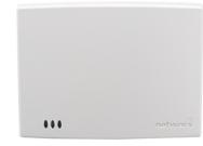
AL-IM2 SERIES Gateway Modules
The ArchiTech series door lock contains a radio that transmits and receives data (via a private wireless signal) to an intermediate device called a "Gateway" interface module. In turn, this module is connected (either wirelessly or wired) to a computer network such as a LAN or corporate Intranet. A Windows PC connected to this network can control and program all ArchiTech series door locks by the use of DL-Windows software (see OI382 and OI383). With access rights to this software, one computer--or several--can control the software and consequently can control the devices in the system. Note: "Version 2" Gateways are the second generation of Networx wireless Gateways. ArchiTech door locks are still compatible with "Version 1" Gateways. Several Gateway device models are available:
AL-IM2-80211 AL-IME2 AL-IME2-POE
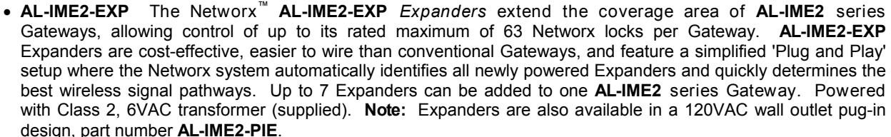
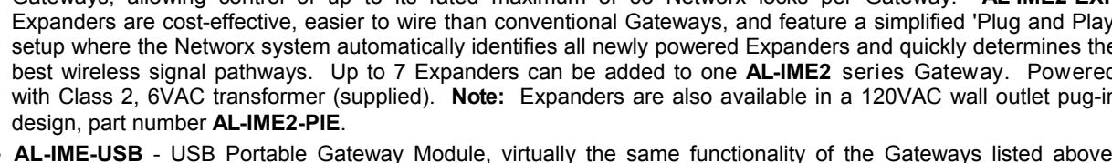
AL-IME2-EXP
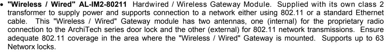
- "Wired" AL-IME2 Hardwired Gateway Module, supports up to 63 Networx locks, connects directly to a network using a standard RJ-45 Ethernet cable. This model has one internal antenna used to transmit to the ArchiTech series door lock via an Alarm Lock proprietary radio connection. Powered with Class 2, 6VAC transformer (supplied).
- "Power over Ethernet" AL-IME2-POE Hardwired Gateway Module + POE (Power Over Ethernet), supports up to 63 Networx locks, connects directly to a network using a standard RJ-45 Ethernet cable and POE. This model has one internal antenna used to transmit to the ArchiTech series door lock via an Alarm Lock proprietary radio connection.
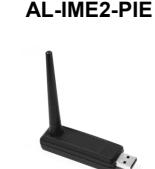
AL-IME-USB - USB Portable Gateway Module, virtually the same functionality of the Gateways listed above, however this highly portable and compact module connects to a standard USB 2.0 socket or greater in your Windows laptop or PC, quickly and effortlessly creating a wireless connection to your ArchiTech series door locks. Requires DL-Windows v5.2 or higher. Note: Only "Local" Emergency Commands are supported when using an AL-IME-USB Gateway. AL-IME-USB
DL-Windows Software
Alarm Lock Trilogy Microsoft Windows-based software, v4.0 or higher, supports Trilogy Networx and Trilogy Stand-Alone locks, with single database (ArchiTech series door locks require v5.2 or higher). For use with Free of charge and downloadable online at www.alarmlock.com. DL-Windows software is the basis for the wireless lock programming interface. Those unfamiliar with using DL-Windows , stop here and review the DL-Windows User's Guide (OI382) and the DL-Windows for Networx User's Guide (OI383).
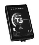
Proximity Card Reader / Enroller
An AL-PRE is used to quickly enroll multiple proximity credentials into DL-Windows. Use the supplied 9-pin DB9 to DB9 serial cable to connect the AL-PRE to your computer's serial COM port. Works with most proximity credentials (37 bits or less; 125kHz).
Proximity Credentials
ArchiTech locks work with most proximity credentials (125kHz Format, 13.56MHz Format depending on lock model).
®
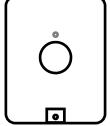
RR-1BUTTON RR-4BKEYFOB
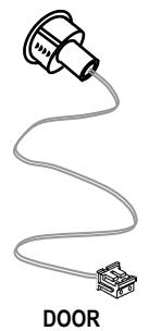
RR-1BUTTON and RR-4BKEYFOB
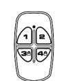
Compatible with the RR-1BUTTON Wireless Remote Release Button (see WI1999) and RR-4BKEYFOB Wireless Remote Release Keyfob (see WI2004). Both can wirelessly unlock all ArchiTech Networx™ series door locks. The RR-4BKEYFOB is a portable pocket-size remote release, and the 1-button RR-1BUTTON is intended for fixed mounting at a hidden location. Each requires one battery (service life of up to 12,000 openings). During normal operation, the lock typically opens within 2 seconds of the button press.

iLock™ Bluetooth LE Smartphone App
Android or iOS smartphone Bluetooth LE application ("app") that allows for manual remote unlock of Alarm Lock ArchiTech series devices (where equipped). For full instructions on using the iLock app, see page 16. Note: Up to 27 Bluetooth Users are supported for any one ArchiTech series lock.
Terminology Used in this Manual
Before reading this section, you may wish to first read the " ArchiTech Series Design Overview " on page 7 to determine the manner in which you will be using your ArchiTech series lock ("DL-Windows Mode" or "Stand-Alone Mode"). For a description of all features, see the DL-Windows User's Guide (OI382) and the DL-Windows for Networx User's Guide (OI383).
What is a Lock Program ?
A Lock Program contains the instructions that a lock uses to perform its various functions. Use DL-Windows (defined below) to create a Lock Program (called a " Lock Profile " in DL-Windows) on your computer, and then transfer and store the Lock Program in the circuitry (firmware) contained inside the lock itself. The Lock Program is essentially a computer database file that maintains feature settings, proximity credential data, Schedules, Audit Trails, etc. Using DL-Windows, Lock Programs can be created with default information, edited on your PC, and then sent to (or received from) locks.
The Lock Program consists of 4 areas: Proximity Credential Entries , Features , Time Zones , and Schedules , all defined below:
What are Proximity Credential Entries ?
Because this lock does not have a keypad, proximity credentials and other types of proximity credentials can be added to the Lock Program to allow entry (to allow the ArchiTech series door lock to unlock). The proximity credential entries are a part of the Lock Program, and the Lock Program is stored in the lock circuitry (firmware) awaiting the Users to present their programmed proximity credentials.
What are Features ?
Your ArchiTech series lock is designed to support many options and functions. Using DL-Windows software (the Programmable Features screen), you can select the features you wish to activate, such as if the lock will automatically adjust for Daylight Saving Time in the spring and autumn, or if the lock sounder should be disabled or enabled. Note: Features may only be added via DL-Windows.
What are Schedules and TimeZones?
You can use DL-Windows to add simple "Schedules" to your ArchiTech series lock. Schedules are events (recorded lock activities) that are assigned to occur automatically at specific times. For example, you can program the lock to allow certain Users access ONLY on Wednesdays.
DL-Windows multiplies your flexibility, allowing the creation of many different combinations of Scheduled events to suit the needs of your various installations. For ex-
ample, you can program the lock to allow Group 1 Users access ONLY during specific business hours (unlock at 9 AM, lock at noon for lunch, unlock at 1 PM, and lock again at 5 PM--every weekday).
In DL-Windows, use the " Schedule - TimeZone " screen to first create an individual block of time called a "TimeZone" (for example, "9 AM to noon weekdays"). A TimeZone is then linked to an event to make a Schedule (for example, "unlock between 9 AM and noon weekdays"). To make Scheduling easier, DL-Windows allows TimeZones to be created, named and saved for the future, to be easily assigned to different events and added to multiple locks as needed. For more details, see the DL-Windows User's Guide (OI382) and the DL-Windows for Networx User's Guide (OI383).
What is a User ?
A User is a person who is authorized to operate the lock and/or make certain programming changes to the lock, depending on their programming abilities. Users can be anyone--from a one-time visitor in possession of a temporary proximity credential (who will almost certainly have no authority to make changes) to the owner of the building in which the lock is installed (who will likely wish to have authority to make programming changes). The ArchiTech series locks can hold up to 5000* Users in its programming memory; in other words, for each lock, you can have up to 5000* Users, each in physical possession of a proximity credential. Note: Users may be enabled, disabled or removed from locks completely, as desired, using DL-Windows. For more information, see OI382.
What is a User Number ?
( User Number = Location Number = User Location = "Slot" in Lock )
User Numbers are used primarily with DL-Windows, and are significant within each individual lock only. (ArchiTech series lock can hold up to 5000* proximity credentials in its programming memory). Each credential can be thought of as an entry in a numbered list, up to 5000*, maintained in the lock's internal database and in DL-Windows respectively. Each entry in this "numbered list" is represented by a User Number, and therefore proximity credential data is assigned to each "location" or "slot" in this list. When a proximity credential is assigned to a location, the credential information is stored within the Lock Program (firmware). Because Users are physically given proximity credentials, it is convenient to think of each "location" as a "User", although technically the User Number is only a location within the Lock Program. In other words, it is easier to say "User 519" rather than " The person in possession of the proximity credential that is assigned to the User Location number 519 ".
Note: Where a User is located in this list--their User
Terminology Used in this Manual (cont'd)
Location --is a commonly used description of their User Number. Because of their similarities, a User Number , User Location and Location Number can be used interchangeably. In some DL-Windows screens, the word "Slot" is also used. All of these terms are meant to convey the same concept.
What is a "Program Card" ?
"Program Cards" are created by the person responsible for programming the ArchiTech series lock when used in "Stand-Alone Mode" (see page 7). Two ordinary proximity cards are provided in the factory packaging, and can be converted into "Program Cards". "Program Cards" allow for the creation of additional proximity credentials and Wireless Remote releases, activating "DL-Windows Mode" ("Networx Mode"), and they also allow access (they can unlock the lock, but we do not recommend they be used as "everyday" access cards). These "Program Cards" are unable to be overwritten by DL-Windows because their proximity data are placed into slots 6000 and 6001 (if used, the audit trail will log them as Users 6000 and 6001). Proximity credentials assigned to User Numbers 2 through 11 are called "Administrative Users", and they possess all the functionality of these two "Program Cards". For a comprehensive understanding, see the " ArchiTech User Number Definitions " table on page 24.
What is a Group ?
With many lock installations, it is convenient for large numbers of similar Users to be grouped together. All of these Users might share some common attribute--for example, they may all work in the same department of a facility, or may all work the same office hours. Placing Users into Groups (by assigning them to a specific range of User Numbers) allows large numbers of Users to be controlled all at once rather than individually--saving time and effort. A typical example involves enabling or disabling a Group at a certain time (assigning them to a Schedule; for example, to allow Group "1" Users access ONLY on Wednesdays).
Who are Users 297-300 ?
Proximity credentials assigned to User Numbers 297, 298, 299 and 300 have special abilities, as follows:
User 297: Quick Enable User 300
The proximity credential assigned to User Number 297 possesses the unique ability to enable the proximity credential assigned to User Number 300. When proximity credential 297 is presented to the lock, proximity credential 300 is enabled for one time use (allowing passage for one time only). Once used, User 300's proximity credential becomes disabled.
For example, you wish to allow one-time access to a temporary worker. Simply present proximity credential 297 to the lock and give proximity credential 300 to the temporary worker. Later, when the temporary worker presents proximity credential 300 to the lock, the lock unlocks and allows access through the door for one time only. Later, if the temporary worker re-presents proximity credential 300 to the lock, access will be denied. If you later wish to grant the temporary worker access again, simply re-present proximity credential 297 to the lock and proximity credential 300 will be reenabled (again for one time only).
User 298 and User 299: Guard Tour
A Guard Tour credential is used to log the movement of a security guard as he or she makes rounds from one assigned guard tour station to the next. Presenting the User 299 proximity credential provides precise verification and accountability of a guard's movement by logging the location with a time and date stamp in the Event Log ("Audit Trail").
Note: Proximity credentials assigned to User 298 and User 299 are not access credentials (meaning these proximity credentials do NOT allow the security guard to pass through the door).
User 300: One-Time-Only Service Credential
This is the credential (given to the service person) that is enabled by the proximity credential assigned to User 297. See User 297: Quick Enable User 300 above.
Who are Bluetooth Users (7000-7026 )
For ArchiTech series locks that contain a Bluetooth LE radio, Bluetooth credentials work just like any other type of proximity credential, but are transmitted from the smartphone app, "iLock". Simply launch the iLock app and tap the Unlock button to allow entry. For more information about using Bluetooth with your lock, see page 16. Note: Up to 27 Bluetooth Users are supported for any one ArchiTech series lock.
What is DL-Windows ?
DL-Windows is a Microsoft Windows-based computer software program that allows you to program your ArchiTech series door lock. With DL-Windows, you can quickly create Lock Programs (called "Lock Profiles" in DL-Windows) that allow you to add multiple proximity credentials, retrieve event logs, create Schedules and program many other features.
The benefit of DL-Windows is that it allows you to set up all lock programming in advance (on your computer), and then later send the information to the locks at your convenience. For more information about DL-Windows, see OI382 and OI383.
* To be exact, 5000 "User Numbers" are available, though not all allow access. For a broader understanding of how these numbers are organized, see " ArchiTech User Number Definitions " on page 24.
ArchiTech Series Design Overview
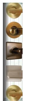
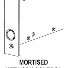
Parts Overview (not to scale)
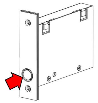
MORTISED NETWORX CONTROL UNIT
SURFACE-MOUNTED NETWORX CONTROL UNIT
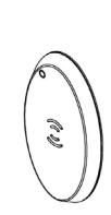
PROXIMITY READER (OVAL)
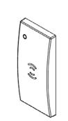
PROXIMITY READER (RECTANGULAR)
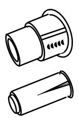
DOOR CONTACT MAGNET (TWO TYPES)
CONTACT SENSOR
Why Use Proximity Credentials?
With ordinary door locks, the need to make physical copies of metal keys and distributing them can be a huge organizational and financial task -- and what will you do if someone causes a security breach by losing their key?
The answer lies in the advantage of "firmware". Firmware exists inside your ArchiTech™ series lock, and can be changed ("programmed") to suit your changing requirements. No more metal keys to distribute...instead, distribute proximity cards and fobs ("credentials"). If lost, they can easily be deleted from the lock firmware. (Proximity cards and fobs are the firmware equivalent of metal keys; just present a valid card to the Proximity Reader to unlock the lock). Furthermore, proximity credentials like cards and fobs differ from metal keys in that they are not duplicates - each credential is "unique" to the lock, and therefore can easily be deleted from the lock firmware without needing to be "in hand". Another advantage is that proximity cards and fobs cannot easily be duplicated, unlike ordinary metal keys.
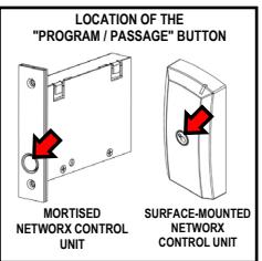
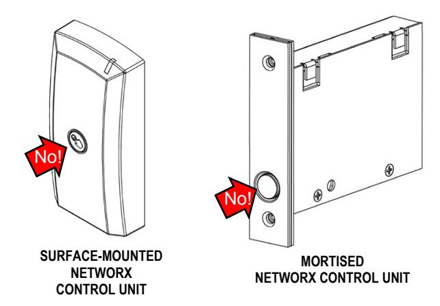
"Program / Passage" button
Much like the classic "rocker switch / stop button" found on a standard mortise lock, the ArchiTech™ Series locks feature a " Program / Passage " button allowing for sustained passage through the door without a credential (see arrows in the images above). These buttons are identical in functionality with each model and are initially used in the " Startup Procedure " process on page 9. During normal operation, the " Program / Passage " button is used to intentionally place the lock into a passage state as needed, without a credential. Note: The " Program / Passage " button is disabled when the door is closed; the door must be open to allow use of the " Program / Passage " button; see next section regarding the Door Contact Sensor and door position monitoring. In addition, the " Program / Passage " button is used for activating (and re-activating) "DL-Windows Mode" and for credential enrollment in "Stand-Alone Mode". Note: The " Program / Passage " button can be disabled using DL-Windows, see page 12.
Door Contact Sensor The Door Contact Sensor is required to monitor the position of the door (open or closed). The Door Contact Sensor is shown above at right; note also that a Sensor is integrated within the edge of the Mortised Networx Control Unit . With the ArchiTech series locks, DL-Windows can program the lock to log a "door position" event or "Door Ajar" event. The lock writes a "Door Ajar" event to the system log or turns on an alert sounder when the Door Contact Sensor contacts remain open past a specified time. In addition, should these contacts detect that the door was opened without first a valid credential unlocking the unit, or the door was opened without first the inside lever being turned, a "Forced Entry" (or door "kick-in") event will be logged, and an alert sounder will turn on for 5 seconds. Note: This "Forced Door Detection" feature, though programmable in DL-Windows, is only available for locks that possess the "RX Request to Exit" functionality.
"Stand-Alone Mode"
Operation of the ArchiTech series lock prior to Networx configuration / "DL-Windows Mode" (enrollment into a Networx system). Wireless Remote Releases, smartphones or proximity cards/fobs are added using your "Program Cards" at the physical lock. Later on, your ArchiTech series lock can be incorporated into a Networx system by performing the "DL-Windows Mode" Re-Activation procedure on page 10. IMPORTANT: All manually added proximity cards and other credentials will be deleted upon the locks' enrollment into the DL-Windows Networx system. For more information about operating in "Stand-Alone Mode", see page 10.
"DL-Windows Mode" ("Networx Mode")
Typical operation after the ArchiTech series lock is enrolled into a Networx system (configuration by the DL-Windows software). All programming (for example adding or deleting proximity cards) is performed using DL-
ArchiTech Series Design Overview (cont'd)
Windows software (version 5.2 or later). By default, after the " Startup Procedure " has been performed (page 9), your ArchiTech series lock is available for discovery by a Networx Gateway and by DL-Windows for a 24 hour "window" of time . DL-Windows communicates with the Gateway module (models listed on page 4) to wirelessly communicate with the lock's internal radio. See the DL-Windows for Networx User's Guide (OI383) for more information about Gateways, and see page 11 for "DL-Windows Mode" operation. Note: Once the lock is enrolled into a Networx system, DL-Windows can toggle a Power Saving Mode to extend battery life (see " Power Saving Mode ON / OFF " on page 13).
Emergency Commands
The ArchiTech series locks respond to Emergency Commands (" Emergency Lock Down ", " Emergency Passage " and " Return to Normal "). In emergencies, a Lock Down command or Unlock command can set all locks to a locked or unlocked state globally in seconds,
initiated from a Wireless Remote Release or initiated from the Networx server running DL-Windows ( Note: Emergency Passage is not available with the Wireless Remote Release). Emergency commands are available in two types: " Global " or " Local ".
- With " Global ", activating the command locks down (or places into passage) the entire system. Locks configured for " Global " also accept and adhere to an Emergency command initiated at another lock via a Wireless Remote Release.
- With " Local ", activating the command does NOT lock down the entire system; only the lock that is "paired" to the Wireless Remote Release will change state (up to 4 locks).
Note: Locks configured as " Local " are not included in " Global " Emergency Commands sent from the Networx Server running DL-Windows. For a full explanation about using Emergency Commands with your ArchiTech series lock, see " ArchiTech Series Features " on page 12.
For further information about how Emergency Commands work with your ENTIRE system, see OI383.
ArchiTech Series Battery Life Maximization
The ArchiTech series locks are equipped with a battery pack containing four (4) standard AA type alkaline batteries, allowing for a 2-5 year life span. To achieve maximum battery life, the ArchiTech series locks allows for an advanced feature called Power Saving Mode whereby an automatic Schedule can be created in DL-Windows to toggle the Mode on or off on a daily/weekly basis. IMPORTANT: During Power Saving Mode, proximity credentials WILL function normally, but ALL communications, including Wireless Remote Releases, will NOT function.
For more information about using Power Saving Mode, see page 13.
ArchiTech Series Startup Procedure
After physically installing your lock, the following startup procedure must be performed for correct lock operation.
POWER UP
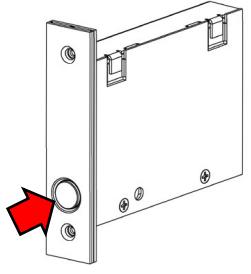
- 1. With the battery disconnected, press and firmly hold the " Program / Passage " button for 15 seconds (button location dependent on model, see illustration at right).
- 2. Release the " Program / Passage " button and reconnect the battery pack. Listen for 3 beeps.
- 3. Press and firmly hold the " Program / Passage " button again until you hear multiple beeps, then release the button.
- 4. The lock will continue to beep and flash the red LED while residual programmed data clears and the lock initializes. A final 2 beep/green flash sequence will occur, indicating successful completion of the power up procedure. Note: This step can take up to 15 seconds.
At this point, by default the ArchiTech series lock is in passage ("unlocked") and is available for discovery by a Networx Gateway and by DL-Windows for the next 24 hours. Next, determine HOW you will be using your ArchiTech series lock by continuing with " MODE SELECTION ", below. Note: The lock will re-lock upon the presentation and acceptance of a valid credential.
MODE SELECTION
Select either " DL-Windows Mode " or " Stand-Alone Mode ":
-
"
DL-Windows Mode
": (Also called "Networx Mode") All lock programming is performed through a Gateway connected to your DL-Windows software. After performing the above "
POWER UP
" steps, the lock is automatically available for discovery by a Networx Gateway and by DL-Windows for the next 24 hours. For information about using DL-Windows and lock discovery, see OI383.
Important:
If the 24 hour window expires before enrolling the lock into DL -Windows, simply repeat the
POWER UP
procedure described above to re-start the 24 hour window.
- For more information on using the ArchiTech series lock in "DL-Windows Mode", see page 11.
- " Stand-Alone Mode ": All programming is performed at the physical lock (no network connectivity). "Program Cards" MUST first be created at the physical lock in order to add additional proximity credentials. Note: Once the two "Program Cards" have been created and are enrolled, the lock is no longer available to be discovered by a Networx system (24 hour window is closed). Create "Program Cards" as follows:
"Program Card" Creation / Enrollment
Have the two ordinary proximity cards (supplied) ready and in your hands before proceeding.
- a. Enter Enroll Mode: Press and release the " Program / Passage " button once (Enroll Mode = continuous beeping with green LED flashes). Note: Enroll Mode will continue for 30 seconds before timing out (ending).
- b. Present the first proximity card to the Proximity Reader . Listen for 2 short confirmation beeps.
- c. Present the second proximity card to the Proximity Reader . Again, listen for 2 short confirmation beeps. If the second card is not enrolled within the 30 second time out, simply press the " Program / Passage " button once to re-start Enroll Mode (with a new 30-second time out).
- d. Exit Enroll Mode: Press and firmly hold the " Program / Passage " button for 4 seconds until you hear a series of beeps. Note: The lock remains in passage (unlocked).
- The two ordinary proximity cards are now "Program Cards". You MUST test each card, as follows:
- e. Present the first of the two "Program Cards". Ensure the lock motor cycles and locks.
- f. Present the second of the two "Program Cards". Again, ensure the lock motor cycles and re-locks (placing the lock into its "normal" locked state). The two "Program Cards" can now be used to enroll additional User access credentials (see page 10). You may wish to consider marking these two "Program Cards" in some way, to allow you distinguish them from other proximity cards. Important: We do not recommend using the "Program Cards" as your "every day" access credentials (therefore the "Program Cards" should be kept in a safe place).
At this point, the ArchiTech series lock is in a locked state, two "Program Cards" have been created and are enrolled, and the lock is no longer available to be discovered by a Networx system (24 hour window is closed). If you later wish to make the lock available to be discovered by a Networx system (i.e. you wish to activate "DL-Windows Mode"), simply follow the " 'DL-Windows Mode' Re-Activation " procedure on page 10.
Note: All ArchiTech series door locks are compatible with the RR-1BUTTON Wireless Remote Release Button (see WI1999) and the RR-4BKEYFOB Wireless Remote Release Keyfob (see WI2004). For VERY important information about pairing Wireless Remote Release buttons, pause here, read page 19 and then resume with the next section below, if needed. In addition, some models are equipped with Bluetooth technology; for information about enrolling Bluetooth credentials, see page 16.
For more information on using the ArchiTech series lock in "Stand-Alone Mode", see page 10.
"Stand-Alone Mode" Operation
As previously described, you can use this ArchiTech series lock in a " Stand-Alone Mode " of operation, as a temporary measure to add credentials to each physical lock prior to Networx integration. However, typical use for the ArchiTech series lock is for use within a wireless Networx system. This section will guide you through adding Users (enrolling proximity credentials) for temporary access before enrolling the lock into to a Networx system.
REMEMBER: All manually added proximity cards and fobs will be deleted upon the locks' enrollment into the DL-Windows Networx system. Note: If you decide to only use your Bluetooth-enabled device as a credential (no proximity cards or keyfobs), once added, the mode automatically changes to " Stand-Alone Mode ".
Manual Credential Enrollment
To manually add additional proximity credentials, you MUST first create / enroll two "Program Cards"; if you have not done so, stop here and perform the "Program Card" Creation / Enrollment on page 9.
Note: If you are enrolling multiple proximity cards, it is a good idea to have all of the cards you wish to enroll handy and ready. Also, be careful not to confuse your two "Program Cards" with your other cards!
- 1. With door in the open position, present either of the two "Program Cards" to the Proximity Reader.
- 2. Within 3 seconds, press and release the " Program / Passage " button. Listen for a series of tones (entering Enroll Mode), followed by continuous beeping with green LED flashes ("in Enroll Mode and waiting for a proximity card or other proximity credential type"). Within 20 seconds perform the next step:
- 3. Present a proximity credential to the Proximity Reader. Upon successful credential enrollment, observe a "Valid Read" indication (two green LEDs and two beeps; see chart on page 23).
- 4. Repeat step 3 for each additional proximity credential you wish to add. Each time an additional credential is added, the lock grants you another 20 seconds to present the next credential. If the 20 second time-out expires (or if a credential fails to be added or read), simply press the " Program / Passage " button and the 20 second Enroll Mode timeout duration will restart.
- 5. After adding your last credential, press and firmly hold the " Program / Passage " button for 4 seconds until you hear a series of beeps ("Exit Enroll Mode" indication; see chart on page 23).
All added credentials are considered "Basic Users" (no programming abilities, cannot enter Enroll Mode and therefore cannot be used as "Program Cards"). If Wireless Remote Releases are to be used in "Stand-Alone Mode" and/or for Emergency Lock Down, please read " Understanding "Global" vs. "Local" " on page 14 and " Wireless Remote Releases " on page 19.
"DL-Windows Mode" Re-Activation
If the 24 hour window for discovery by DL-Windows has expired, or if you wish to migrate from "Stand-Alone Mode" to "DL-Windows Mode", the lock may be restored to its original factory condition (see Erase All Programing on page 21) or the following procedure may be performed to make the ArchiTech series lock available for discovery by DL-Windows version 5.2 or later.
The procedure below describes how to re-activate "DL-Windows Mode" using your previously created "Program Cards".
- 1. With the door open, present one of the previously created "Program Cards" to the Proximity Reader.
- 2. Press and firmly hold the " Program / Passage " button for 6 seconds until the Proximity Reader LED flashes green twice and beeps twice.
- 3. Release the " Program / Passage " button.
Note: While the " Program / Passage " button is being held down in step 2, the door will remain unlocked for the length of the button press.
The ArchiTech series lock is now available for discovery by DL-Windows. WARNING! Cards and other credentials added in "Stand-Alone Mode" will be deleted!
"DL-Windows Mode" Operation / Features
This section highlights the considerations when using the ArchiTech series lock in a mode integrated with the DL-Windows software (version 5.2 and up). When using the lock in "DL-Windows Mode" (also called "Networx Mode"), credentials and lock features can be sent to the lock wirelessly using a Networx Gateway. For different types of Gateway modules, see page 4. Note: After lock has been configured (added) to the Networx Gateway, it will remain unlocked until a valid credential is presented to the Proximity Reader.
IMPORTANT: All proximity credentials manually added in "Stand-Alone Mode" will be deleted upon the locks' enrollment into the DL-Windows Networx system.
If you are new to DL-Windows and Networx, stop here and read the DL-Windows User Guide (OI382) for a basic overview of DL-Windows. Many of the terms detailed in this manual are explained in OI382 and also the DL-Windows for Networx User Guide (OI383).
Lock Types
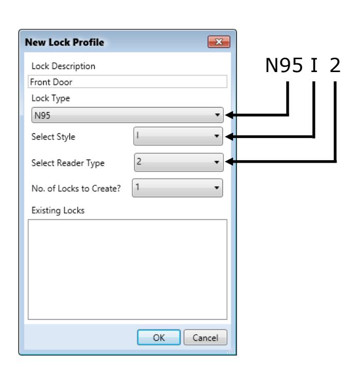
The ArchiTech series locks are available in various design combinations, therefore the " Lock Types " in DL-Windows must be carefully selected. Use the control unit label (example shown at right) to make the proper selections in the DL-Windows New Lock Profile screen. Note: An identical label is located on the provided yellow Lock ID card.
N95I2 52BB6974
An example " N95I2 " Lock Type selection is shown below:
Note: Correct "Lock Types" are required for successfully linking a physical lock to the DL-Windows "Lock Profile" (see " What is a Lock Program? " on page 5 for further information).
Temporary Credentials
tial will be written into slot 17.
Proximity credentials added during "Stand-Alone Mode" are deleted upon enrollment into the DL-Windows Networx system. Even after Networx enrollment and integration, proximity credentials may still be manually added, just like in "Stand-Alone Mode". However, upon sending a Lock Profile from DL-Windows to the lock, all manually added cards and other credentials will be overwritten and/or deleted . Though not recommended, if proximity credentials are manually added in "DL-Windows Mode", they will be added to the next available slot. For example, if you already add-
ed credentials to slots 12-16, the manually added creden-
"Program Card" Considerations
- If "Program Cards" were created / enrolled ("Stand-Alone Mode") prior to integration with DL-Windows, the "Program Cards" will NOT be overwritten and will remain in the lock memory.
- "Program Cards" are added to slots 6000 and 6001, and are logged accordingly.
- "Program Cards" have the same functionality as Administrative Users (credentials added to any of the slots numbered 2 through 11 in DL-Windows). See the " ArchiTech User Number Definitions " chart on page 24.
"DL-Windows Mode" Operation / Features (cont'd)
ArchiTech Series Features
ArchiTech series locks support most standard Networx features (e.g. Entry Delay, GP2 Toggles Passage Mode, etc.) that are available in DL-Windows. For more information regarding all of the features available with your ArchiTech series lock, see OI382 and OI383. Below are descriptions of several features and functions pertaining to the ArchiTech series models enrolled within a Networx system. Note: See the Glossary definition of " DEFAULT " on page 28 before proceeding.
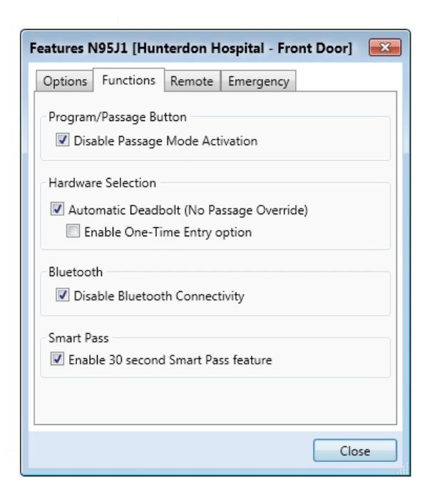
Functions Tab
Program / Passage Button
By default the " Program / Passage " button is enabled, allowing for the sustained passage through the door without a credential. If you check the Disable Passage Mode Activation check box, the " Program / Passage " button will be disabled, thus disallowing sustained Passage Mode via the " Program / Passage " button. Note: The " Program / Passage " button's use with programming is not affected (for information about the " Program / Passage " buttonsee page 7).
Hardware Selection
Automatic Deadbolt
The ArchiTech 9500 series (mortise) locks can be used with an "automatic" deadbolt causing the deadbolt to be extended immediately upon door closure. Because an extended deadbolt (by default) cancels Passage mode, if you wish for Passage Mode to be sustained after an automatic deadbolt extension, the Automatic Deadbolt checkbox must be checked.
Therefore, if Automatic Deadbolt is checked, Passage Mode (via an unlock Schedule or " Program / Passage "
button press, etc.) will be sustained indefinitely until cancelled (via a lock Schedule or subsequent " Program / Passage " button press).
Enable One-Time Entry option
Used with the above-described Automatic Deadbolt function, the Enable One-Time Entry option allows for Passage Mode to be automatically canceled after the door is closed for a second time. Thus, if a door (equipped with an "automatic" deadbolt) is opened, and sustained Passage Mode is enabled via a " Program / Passage " button press, the door can be closed, re-opened (without a credential) and will lock upon a second door closure.
IMPORTANT: A 15 second "window of opportunity" begins after the first door closure allowing re-entry and re-exit (second door closure) without canceling sustained Passage.
Note: The above function is dependent on the position of the deadbolt, not the door position (Door Contact Sensor is not required for this function).
Bluetooth
For ArchiTech series models that are equipped with Bluetooth LE technology, if you wish to disable Bluetooth connectivity for a specific Lock Profile (lock will ignore Bluetooth credentials), check the Disable Bluetooth Connectivity checkbox. For more information about Bluetooth connectivity, see page 16.
Smart Pass
After a valid credential has been presented, the ArchiTech series lock will remain unlocked for 30 seconds OR until the door closes. Enabling this feature overrides the existing Pass Time duration. Note: The above function is dependent upon the door position (Door Contact Sensor required).
"DL-Windows Mode" Operation / Features (cont'd)
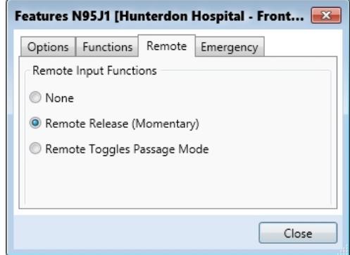
Remote Tab
The ArchiTech series locks allow for two programmable remote functions: Remote Release (Momentary) and Remote Toggles Passage Mode . For complete information about these DL-Windows features, see OI382 and its pages detailing the Features screen.
These remote release features can only be triggered by use of the RR-1BUTTON Wireless Remote Release Button (see WI1999) and/or the RR-4BKEYFOB Wireless Remote Release Keyfob (see WI2004).
Note: If Remote Toggles Passage Mode is enabled, and a Wireless Remote Release button press placed the ArchiTech series lock in an unlocked state (passage), the press and release of the " Program / Passage " button will take the lock out of passage (locking the lock). The opposite is also true: If a Wireless Remote Release button press placed the ArchiTech series lock in a locked state, the press and release of the " Program / Passage " button will place the lock in passage (unlocking the lock).
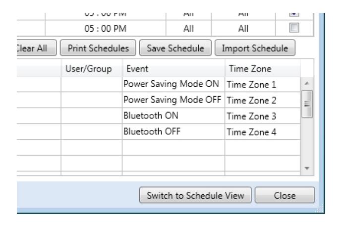
ArchiTech Series Scheduled Events
DL-Windows software allows you to create Schedules containing "Events". ArchiTech series locks support all standard scheduled Events such as Unlock , Disable Group , Enable User , etc., with two additional Events, Power Saving Mode and Bluetooth ON/OFF . For more information regarding all of the scheduled Events available, creating Time Zones and Events in the DL-Windows Schedule Screen, refer to OI382 and OI383.
Power Saving Mode ON / OFF
The ArchiTech series locks can be placed into a Power Saving Mode for specified periods of time. By creating Power Saving Mode Events, the lifespan of the batteries can be greatly increased.
For example, if the ArchiTech series lock is installed inside a business office where the office closes and remains empty at night, a Schedule can be created to place the ArchiTech series lock into a Power Saving Mode, from 5:05 PM through 9:00 AM every weekday.
Schedules for weekends and holidays can also be created to suit the specific circumstances of the installation, maximizing battery life even further.
IMPORTANT: During Power Saving Mode, proximity credentials WILL function normally, but ALL communica-
tions, including Wireless Remote Releases, will NOT function.
To place the ArchiTech series lock into a Power Saving Mode via a Schedule, select " Power Saving Mode On " in the Event column located in the Schedule Entry area. See image at right for an example " Power Saving Mode On " selection.
Bluetooth ON / OFF
For ArchiTech series models that support Bluetooth, the internal Bluetooth radio can be toggled on and off, as desired. Turning the Bluetooth radio off will deny access to Bluetooth Users and will also increase the lifespan of the batteries.
For example, if the ArchiTech series lock is installed inside a business office where the office closes and Bluetooth Users should be denied access, a Schedule can be created to turn off the Bluetooth radio from 5:05 PM through 9:00 AM every weekday, thus ignoring all Bluetooth credentials.
To disable Bluetooth in an ArchiTech series lock via a Schedule, select " Bluetooth OFF " in the Event column located in the Schedule Entry area. See the accompanying image for an example " Bluetooth ON / OFF " selection.
TIP: Like all scheduled Events, Power Saving Mode or Bluetooth ON / OFF may be programmed to coincide with other Schedules. For example, the lock can lock every day at 5:00 PM and also begin Power Saving Mode at 5:00 PM.
Emergency Commands
Overview
The ArchiTech series locks can be programmed to send and/or respond to Emergency Commands (" Emergency Lock Down ", " Emergency Passage " and " Return to Normal "). Emergency Commands can be initiated an RR-4BKEYFOB Wireless Remote Release or initiated from the Networx server running DL-Windows. ( Note: " Emergency Passage " is not available with the Wireless Remote Release ). Emergency Commands are available in two types: " Global " or " Local ".
- With " Global Emergency Commands ", activating the Emergency Command changes the state of all locks in the entire system.
- With " Local Emergency Commands ", only the lock that initiates the Emergency Command will change state; activating the Emergency Command does NOT change the state of all locks in the entire system.
For more information about how Emergency Commands work with your ENTIRE system, see the DL-Windows for Networx User's Guide (OI383).
Understanding "Global" vs. "Local"
The following features should be understood before using Emergency Commands with your ArchiTech series lock. Below describes the various features available for Global Emergency Commands or Local Emergency Commands , or combinations of both.
TIP: If using an RR-4BKEYFOB Wireless Remote Release , before reading this page, we recommend that you read the documentation that came with it, and also the " Wireless Remote Releases " section on page 19.
Receiving Emergency Commands
Lock Responds to Global Emergency Commands
- When enabled: The lock WILL accept and adhere to Emergency Commands that disseminate from another lock or from DL-Windows. Note: This feature does not need to be enabled (checked) for the lock to accept commands from an RR-4BKEYFOB Wireless Remote Release .
- When disabled: The lock WILL NOT accept nor adhere to Emergency Commands that disseminate from another lock or from DL-Windows. CAUTION: Disabling (unchecking) this feature could be of great consequence for the safe administration of your Networx system.
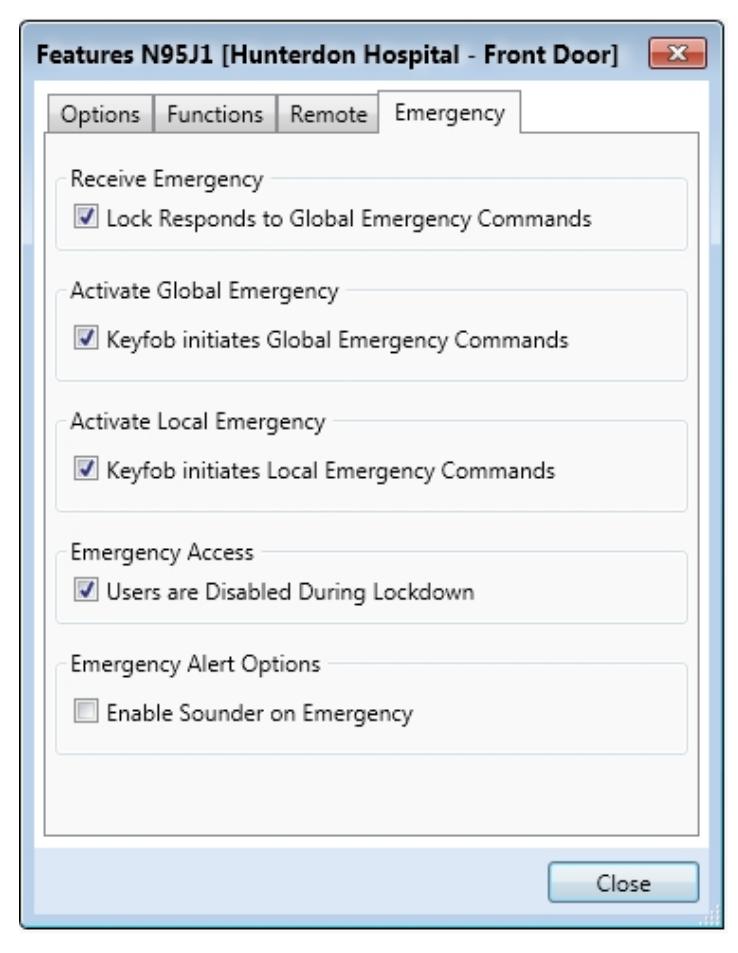
Activating Global Emergency Commands
Keyfob initiates Global Emergency Commands : When enabled (checked), if an Emergency Command is initiated from an RR-4BKEYFOB Wireless Remote Release , the "paired" lock will first inform the Gateway to broadcast the Emergency Command to all locks assigned to the same " Gateway Group ", then the paired lock will respond to that Emergency Command accordingly (if the above " Lock Responds to Global Emergency Commands " is enabled).
Note: See OI383 for more information about Gateway Emergency Groups.
Activating Local Emergency Commands
Keyfob initiates Local Emergency Commands : When enabled (checked), if an Emergency Command is initiated from an RR-4BKEYFOB Wireless Remote Release , the paired lock will immediately change state accord-
Emergency Commands (cont'd)
ingly. The Emergency Command will NOT be sent to the Gateway and therefore will NOT be sent to other locks in the system.
TIP: Combining Global and Local Features: You can combine the various Global and Local Emergency features to customize your system.
Example #1: DL-Windows by default enables (checks) all of the features, as shown above in the Features dialog. What will happen when all features are enabled and an " Emergency Lock Down " command is initiated from a keyfob? Because the Activate Local Emergency commands are enabled, the lock that receives and initiates the Emergency Command will lock down, then the lock will inform the Gateway to broadcast the Emergency Command to all locks assigned to the same " Gateway Group ".
Example #2: This example is known as the "pull station option", where the Activate Global Emergency command is checked, the Activating Local Emergency command is not checked, and the " Lock Responds to Global Emergency Commands " is unchecked. If an " Emergency Lock Down " command is then initiated, the lock will first inform the Gateway to broadcast the Emergency Command to all locks assigned to the same " Gateway Group ", then the lock will ignore the broadcast when received.
Emergency Users
Access During an Emergency
- When enabled: If the feature Users are Disabled During Lockdown is enabled (checked) for a specific lock, and when the Networx system is in an Emergency Lock Down state, "Basic Users" (Users 12+) are denied the ability to unlock the physical lock (credentials for these Basic Users are ignored). The proximity credentials added as Administrative Users (Users 2 through 11), "Program Cards", Bluetooth credentials, as well as all "Emergency Users" remain enabled , retaining the ability to unlock a secured lock.
- When disabled: If the feature Users are Disabled During Lockdown is disabled (unchecked) for a specific lock, and when the Networx system is in an Emergency Lock Down state, ANY valid credential that exists in the lock's internal memory will be allowed to unlock the secured lock, regardless of User Number.
Emergency Alert Options
Sounder
If Enable Sounder on Emergency is enabled (checked), upon receiving an Emergency Command, the integral sounder will beep once per second for 30 seconds.
Tip: Only "Local" Emergency Commands are supported when using an AL-IME-USB Gateway . See page 4 for Gateway model descriptions.
Bluetooth Support

Overview
The J and T "style" ArchiTech series locks contain Bluetooth LE technology that allows for entry via a smartphone application ("app"). The iLock smartphone app works essentially as any other type of proximity credential; simply launch the iLock app and tap the Unlock button to allow entry. For added security, an optional password can be set in the iLock app that would then be required for every unlock request. Note: Up to 27 Bluetooth Users are supported for any one ArchiTech series lock.
Downloading the iLock App
- For iPhone Users: Go to your iTunes store, search for "iLock" and download the app.
- For Android Users: Go to your Google Play store, search for "iLock" and download the app.
Note: The following special permissions are required:
- Device Location
- File Access.
Enrolling Bluetooth Credentials
After the iLock app has been downloaded and installed on your smartphone:
- 1. Run the iLock app and the Settings screen opens.
- 2. Place the ArchiTech series lock into Enroll Mode by pressing the " Program / Passage " button once (Enroll Mode = continuous beeping with green LED flashes).
Depending on the Mode of the lock (see page 9), Enroll Mode is entered as follows:
- Initial lock startup : Simply press the " Program / Passage " button once
- Stand-Alone Mode : Present a "Program Card" and with the state of the lock "unlocked" , press the " Program / Passage " button once
- DL-Windows Mode : Present a "Program Card" OR any Administrative User (2-11); with the state of the lock "unlocked", press " Program / Passage " button once
- 3. Within 30 seconds, tap " Add a New Lock " on the iLock app.
- 4. In the Select Lock screen, select the lock that appears. Lock acknowledges with two beeps.
-
5. Within 120 seconds, enter a
Lock Name
and password (maximum 20 alphanumeric characters).
- Successful Pairing: Lock sounds 4 beeps with 4 green LED flashes
- Unsuccessful Pairing: Lock sounds 7 beeps with 7 red LED flashes.
- 6. Exit Enroll Mode: Press and firmly hold the " Program / Passage " button for 4 seconds until you hear a series of beeps.
Follow the above steps for each additional Bluetooth credential.
Bluetooth Credential Considerations
- If Bluetooth credentials were created / enrolled ("Stand-Alone Mode") prior to integration with DL-Windows, the Bluetooth credentials will NOT be overwritten and will remain in the lock memory.
- Bluetooth credentials are added to slots 7000 through 7026, and are logged accordingly.
- The first two Bluetooth credentials added (slots 7000, 7001) have the same functionality as Administrative Users (credentials added to any of the slots numbered 2 through 11 in DL-Windows). Therefore, the first two Bluetooth Users have the ability to add additional Bluetooth credentials. See the " ArchiTech User Number Definitions " chart on page 24.
Using the iLock App
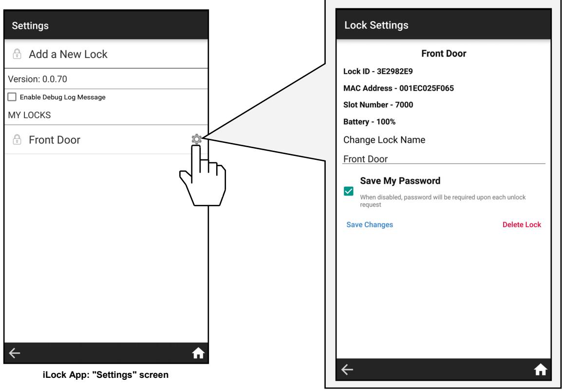
iLock App: "Lock Settings" screen (see below)
Lock Settings
Lock ID
(Lock Serial Number): Displays the physical lock's unique serial number assigned and programmed into the lock firmware at the factory. Networx locks are identified in DL-Windows by this unique serial number.
MAC Address:
Displays the unique 12-digit MAC address of the Bluetooth radio module of the selected lock.
Slot Number
Used interchangeably with User Number , this number represents the location within the lock's internal programming memory. The location and therefore the Slot Number determines the abilities of that User. The first two Bluetooth Users are always added to slots 7000 and 7001 respectively; these Users have Administrative rights. All subsequently added Bluetooth Users (7002 - 7026) are "Basic" Users. For more information about ArchiTech User Number Definitions, see page 24.
Battery
Indicates the latest percentage of remaining usable capacity of the battery in the selected lock, (updated upon each successful communication). Important: The percentage will equal zero upon a Low Battery Warning indication (see page 20), therefore 50% represents halfway to a Low Battery state .
Change Lock Name
Displays existing Lock Name created in step 5 in "Enrolling Bluetooth Credentials" above. Upon selection, smartphone keyboard will appear allowing changes. Note: Tap " Save Changes " to retain all edits.
"Save My Password" Feature
Checked (enabled) by default, password created in step 5 in "Enrolling Bluetooth Credentials" above is not required for each unlock request. When unchecked (disabled), each time the Unlock Button is selected from the home screen a prompt will appear to enter your password.
Save Changes
Retains changes to the Lock Name or the "Save My Password" Feature.
Delete Lock
Removes the selected Networx lock from the iLock app.
Using the iLock App (cont'd)
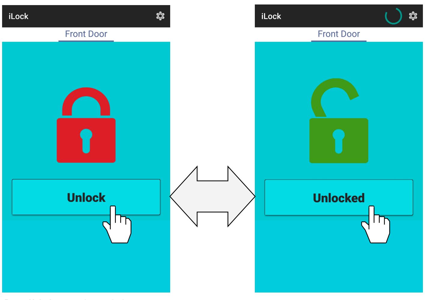
Press Unlock to send an unlock request to the selected ArchiTech series lock. The lock will unlock within a few seconds (this time varies with smartphone models).
Red padlock turns green upon unlock (and remains green / unlocked for the duration of the programmed Pass Time).
Wireless Remote Releases
Two types of "Wireless Remote Release" devices are compatible with the ArchiTech series door locks: The RR-1BUTTON Wireless Remote Release Button (see WI1999) and RR-4BKEYFOB Wireless Remote Release Keyfob (see WI2004). Whether the Wireless Remote Release contains a single button (RR-1BUTTON) or four buttons (RR-4BKEYFOB), each button can be "paired" (connected) with one ArchiTech series lock. This means, for example, the four buttons on the RR-4BKEYFOB can each be paired with four separate ArchiTech series locks. In addition, each individual ArchiTech series lock contains ten (10) "slots" ("User Numbers"), and each "slot" is available to accommodate one paired Wireless Remote Release button. Therefore, each individual ArchiTech series lock can ultimately be paired with up to ten Wireless Remote Release buttons on multiple Wireless Remote Release devices.
Note: Since each button can ONLY be paired with one specific Networx-integrated ArchiTech series lock at a time, when a previously paired button is later paired with a second locking device, the first pairing is erased.
Before you "pair" (connect) your Wireless Remote Release buttons, here are some important things to consider:
- Though Wireless Remote Releases can be enrolled when the lock is in "Stand-Alone Mode", migration to "DL-Windows Mode" after Wireless Remote Releases are enrolled requires that the lock be defaulted and re-initialized (page 21), clearing all previously programmed Users and/or paired Wireless Remote Releases .
- If your lock has been placed into a Power Saving Mode via a DL-Windows Schedule, Wireless Remote Releases will NOT function.
Pairing Wireless Remote Release Buttons
Before you begin, note that the pairing steps below must all be performed within thirty (30) seconds. Ten of the thirty seconds are used during step 3, leaving little time for error or delays. Therefore, before proceeding, read through the steps first to become familiar with this simple procedure.
- 1. Select a Wireless Remote Release "button" you wish to pair. Selecting a button in advance will greatly assist this process. Keep the Wireless Remote Release in your hand as you perform the next steps.
- 2. Place the ArchiTech series lock into Enroll Mode by pressing the " Program / Passage " button once (Enroll Mode = continuous beeping with green LED flashes). The 30 second timeout begins now.
Depending on the Mode of the lock (see page 9), Enroll Mode is entered as follows:
- Initial lock startup : Simply press the " Program / Passage " button once
- Stand-Alone Mode : Present a "Program Card" and with the door open, press the " Program / Passage " button once
- DL-Windows Mode : Present a "Program Card" OR any Administrative User (2-11); with the door open, press " Program / Passage " button once
-
3. Immediately
press and hold
the Remote Release button and observe the Remote Release LED:
- a. The red LED lights...keep holding the button…
- b. The LED flashes green, release the button...
-
c. Wait and observe the LED as follows:
- LED solid green = Pairing successful (also a double-beep and green LED on the Proximity Reader)
- LED solid red = Pairing unsuccessful, start again at step 1.
- 4. Exit Enroll Mode: Press and firmly hold the " Program / Passage " button for 4 seconds until you hear a series of beeps.
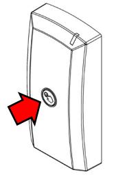
MORTISED NETWORX CONTROL UNIT SURFACE-MOUNTED NETWORX CONTROL UNIT
LOCATION OF THE "PROGRAM / PASSAGE" BUTTON
Emergency Lock Down (via Wireless Remote Release) The ArchiTech series locks have the added ability to accept Emergency Lock Down commands from a Wireless Remote Release (model RR-4BKEYFOB only). When buttons 3 and 4 are pressed simultaneously, within seconds an Emergency Lock Down command is sent to all locks to which the RR-4BKEYFOB is currently paired (up to 4). Conversely, pressing buttons 1 and 2 simultaneously will send a
Return to Normal command, returning the paired locks back to the state they were in prior to receiving the Emergency Lock Down command. See page 14 for the two different modes ( Understanding "Global" vs. "Local" ) to which the ArchiTech series locks respond when an Emergency Command when sent from a Wireless Remote Release.
RR-4BKEYFOB
Low Battery and Battery Replacement
Low Battery Warning
When a valid proximity credential is presented to the lock and the batteries are weak, a steady tone will sound for the duration of the Pass Time ("Pass Time" is the duration the lock remains unlocked after access is granted). Discard the weak batteries and replace with four (4) AA-size 1.5 volt alkaline batteries. Always replace weak batteries as soon as possible.
Battery Replacement
The batteries are located within the Control Unit (each type pictured below), therefore the battery replacement steps will vary with the design. Avoid pressing the " Program / Passage " button during this procedure (see diagram on page 9).
To replace batteries in the Mortised Networx Control Unit :
- 1. Remove the two 8-32 x 1/4" Phillips Flat-Head screws that secure the flush Finishing Plate that covers the Mortised Networx Control Unit . Put screws aside in a safe place.
- 2. The Finishing Plate is connected to the internal PC board with a wire (take note of how the wire was placed under the PC board at the factory). Gently lift and move the Finishing Plate to the side.
- 3. Pull out the battery connector wires and disconnect the plugs.
- 4. Taking note of its original orientation, pull out the battery pack.
- 5. Remove the screw securing the battery pack top cover, then lift the top cover. Remove all weak batteries and replace with fresh batteries, observing polarity. NEVER mix weak batteries with fresh batteries.
- 6. Replace the battery pack top cover and secure with the screw. Insert the battery pack in the same orientation as its removal in step 4.
- 7. Connect the battery connector plug. If you do not hear 3 beeps when power is re-applied, all programming and settings have been retained, and the lock will be ready for use. If you do hear 3 beeps when power is re-applied, wait 15 seconds for the LED to flash red 7 times and 7 beeps will sound (the clock will need to be reset using DL-Windows).
NETWORX CONTROL UNIT
- 8. Gently push the battery wires (and any other loose wires) back into the Control Unit .
- 9. Return the Finishing Plate to its original location and secure with the two 8-32 x 1/4" Phillips Flat-Head screws.
To replace batteries in the Surface-Mounted Networx Control Unit :
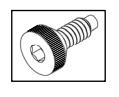
- 1. Using the supplied Allen key, remove the mounting screw (#6-32 Allen Head countersunk Ucut Dog Point screw, part #SC681, shown at right). Put screw aside in a safe place.
- 2. Lift the bottom of the Surface-Mounted Networx Control Unit and unhook the top. Gently lift from the door surface; do not pull wires. It is OK to let the unit "hang" from the door.


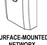
SURFACE-MOUNTED NETWORX CONTROL UNIT
- 6. Replace the battery pack top cover and secure with two screws. Insert the battery pack in the same orientation as its removal in step 5.
- 7. Insert the white battery plug into the white socket and press firmly until secure. If you do not hear 3 beeps when power is re-applied, all programming and settings have been retained, and the lock will be ready for use. If you do hear 3 beeps when power is re-applied, wait 15 seconds for the LED to flash red 7 times and 7 beeps will sound (the clock will need to be reset using DL-Windows).
- 8. Ensure all wires are pushed back into the door to avoid pinching wires. Carefully hook the top of the Surface-Mounted Networx Control Unit into the top of the Control Unit Mounting Plate (see installation instructions if necessary) and press the bottom until flush with the door surface. Replace the #6-32 Allen Head countersunk U-cut Dog Point screw (part #SC681 as shown above) at the bottom of the Surface-Mounted Networx Control Unit and tighten securely. Replace all hardware removed as required.
Erase All Programming
Erase All Programming (Restore the "out of box" factory condition)
To return the ArchiTech series lock to its original condition, when the lock and all components were first removed from their factory packaging, proceed as follows for the specific model type in your installation:
To erase all programming in the Mortised Networx Control Unit :
- 1. Remove the two 8-32 x 1/4" Phillips Flat-Head screws that secure the flush Finishing Plate that covers the Mortised Networx Control Unit . Put screws aside in a safe place.
- 2. The Finishing Plate is connected to the internal PC board with a wire (take note of how the wire is placed under the PC board at the factory). Gently lift and move the Finishing Plate to the side.
- 3. Pull out the battery connector wires and disconnect the plugs.
- 4. Press and hold the " Program / Passage " button (see arrow in image at right) for 15 seconds, then release.
- 5. Reconnect the battery connector plug. Listen for 3 beeps. Press and firmly hold the " Program / Passage " button again until you hear multiple beeps, then release the button. The lock will continue to beep and flash the red LED while residual programmed data clears and the lock initializes. A final 2 beep/green flash sequence will occur, indicating successful completion of the power up procedure. Note: This step can take up to 15 seconds.
MORTISED NETWORX CONTROL UNIT
- 6. Gently push the battery wires (and any other loose wires) back into the Control Unit .
- 7. Return the Finishing Plate to its original location and secure with the two 8-32 x 1/4" Phillips Flat-Head screws.
To erase all programming in the Surface-Mounted Networx Control Unit :
1. Using the supplied Allen key, remove the mounting screw located in the previous step (#6-32 Allen Head countersunk U-cut Dog Point screw, part #SC681, shown at right). Put screw aside in a safe place.
- 2. Lift the bottom of the Surface-Mounted Networx Control Unit and unhook the top. Gently lift from the door surface; do not pull wires. It is OK to let the unit "hang" from the door.
- 3. With two fingers, firmly grasp the battery wires connected to the white plug. Pull the wires until the plug releases from the white female socket. It is OK to use some force in this step.
- 4. Press and hold the " Program / Passage " button (see arrow in image at right) for 15 seconds, then release.
- 5. Re-insert the white battery plug into the white socket and press firmly until secure. Listen for 3 beeps. Press and firmly hold the " Program / Passage " button again until you hear multiple beeps, then release the button. The lock will continue to beep and flash the red LED while residual programmed data clears and the lock initializes. A final 2 beep/green flash sequence will occur, indicating successful completion of the power up procedure. Note: This step can take up to 15 seconds. SURFACE-MOUNTED NETWORX CONTROL UNIT
- 6. Ensure all wires are pushed back into the door to avoid pinching wires. Carefully hook the top of the Surface-Mounted Networx Control Unit into the top of the Control Unit Mounting Plate (see installation instructions if necessary) and press the bottom until flush with the door surface. Replace the #6-32 Allen Head countersunk U-cut Dog Point screw (part #SC681 as shown above) at the bottom of the Surface-Mounted Networx Control Unit and tighten securely. Replace all hardware removed as required.
Power Down -- Retain Existing Programming
Power Down--Retain Existing Programming
Use when re-applying power to a lock already in use (you wish to retain the Lock Program), such as when moving an existing lock to a new door or changing the batteries. In this case, the lock is to be dismantled and powered down for an extended period.
Follow all the steps for " Low Battery and Battery Replacement " on page 20 for the Control Unit installed, however DO NOT touch the " Program / Passage " button AT ANY TIME during the procedure.
If the lock is powered down for an extended period of time, and if you do not hear 3 beeps when power is re-applied, all programming and settings have been retained, and the lock will be ready for use.
If you do hear 3 beeps when power is re-applied, wait 15 seconds for the LED to flash red 7 times and 7 beeps will sound (the clock will need to be reset using DL-Windows).
LED and Sounder Indications
With a fully charged battery, the LED and sounder provide visual and audible feedback. The LED on the Surface-Mounted Networx Control Unit mimics the LED located on the Proximity Reader .
| ACTIVITY |
LED
FLASHES |
SOUNDER
BEEP(S) |
COMMENTS |
|---|---|---|---|
|
Access Granted / Wireless Remote
Release button press |
2 Green | 2 | Lock unlocks for duration of Pass Time ("Pass Time" is the duration the lock remains unlocked after access is granted). |
| Invalid Credential | 7 Red | 7 | Invalid proximity credential presented that does not exist in the Lock Program memory. |
|
"Program / Passage" button press
(while door is open) |
2 Green | 2 | Passage mode toggled. |
|
Successful Credential Enrollment
(Valid Read) |
2 Green | 2 | Proximity credential added to Lock Program memory successfully. |
|
Unsuccessful Credential Enrollment
(Invalid Read) |
7 Red | 7 | Proximity credential enrollment denied (Lock Program memory full, credential already exists, credential not fully read by Proximity Reader, etc.). |
| Enter Enroll Mode | 1 Red, 2 Green | 10 |
Sounder cadence shorter for entering Enroll
Mode compared with exiting. |
| Exit Enroll Mode | 1 Red, 2 Green | 10 | This red LED and sounder combination denotes a "Successful" Enroll Mode exit. Sounder cadence longer for exiting Enroll Mode compared with entering. |
| Waiting for credential (in Enroll Mode) |
Rapid Green for
25 seconds, then Red for final 5 seconds |
Rapid beeps for entire 30 second duration | Automatically times out after 30 seconds total. |
| Valid but Disabled Credential | 1 Green, 4 Red | 1 long, 5 short | Credential exists in Lock Program memory, but is disabled. |
| Emergency Commands are in effect | 1 Red every two seconds | See page 14; also see Ol382 and Ol383 for more information. | |
| Low Battery Warning | Red LED and sounder steady during Pass Time | ("Pass Time" is the duration the lock remains unlocked after access is granted). See page 20 before changing batteries. | |
| "DL-Windows Mode" Re-activated | 2 Green | 2 | Manually enabled "DL-Windows Mode". |
| Door Ajar Sounder |
eep every second
seconds |
Occurs after Door Ajar Trip Time expires. "Sounder on Door Ajar" feature must be programmed. See page 7, "Door Contact Sensor". | |
ArchiTech User Number Definitions
Adding Extra "Admin" Credentials
Some of the terminology in this table was originally defined in the DL-Windows User Guide OI382. Please refer to this manual for specific definitions. For more information, see Terminology on page 5 and page 6, and also see OI383. Proximity credentials assigned to User Numbers 2 through 11 are called "Administrative Users", and they possess all the functionality of the two "Program Cards" that reside in slots 6000 and 6001.
| USER TYPE |
USER
NUMBER |
FUNCTIONALITY / COMMENTS |
|---|---|---|
| Master Code | 1 | User Number 1 is unavailable; credentials cannot be added to this slot. |
|
Installer 1
Installer 2 |
2 & 3 |
These are Administrative Users. Programming ability (able to place lock into Enroll
Mode and to enroll additional Basic User credentials or a Wireless Remote Release), Emergency User (during an Emergency state, credential can unlock the physical lock for the duration of the Pass Time). |
|
Manager 1
Manager 2 Manager 3 |
4 - 6 |
These are Administrative Users. Programming ability (able to place lock into Enroll
Mode and to enroll additional Basic User credentials or a Wireless Remote Release), Emergency User (during an Emergency state, credential can unlock the physical lock for the duration of the Pass Time). |
|
Supervisor 1
Supervisor 2 Supervisor 3 |
7 - 9 |
These are Administrative Users. Programming ability (able to place lock into Enroll
Mode and to enroll additional Basic User credentials or a Wireless Remote Release), Emergency User (during an Emergency state, credential can unlock the physical lock for the duration of the Pass Time). |
|
Reserved ("Print Only 1")
Reserved ("Print Only 2") |
10 - 11 |
These are Administrative Users. Programming ability (able to place lock into Enroll
Mode and to enroll additional Basic User credentials or a Wireless Remote Release), Emergency User (during an Emergency state, credential can unlock the physical lock for the duration of the Pass Time). Note: The description "Print Only" was carried over from legacy lock types, and is retained for consistency of DL-Windows screens. However, these Users have the same Administrative User abilities as Users 2-9. |
| Basic Users* | 12 - 5000 | No programming and no Administrative User abilities. |
| Enable User 300 | 297 |
Present credential to enable "One-Time Only Service" User (User Number 300).
Includes Basic User functionality. |
|
Guard Tour 1
Guard Tour 2 |
298, 299 |
Non-passage User (does not unlock the lock), meant to be used for logging activity.
Note: The description "Guard Tour" was carried over from legacy lock types, and is retained for consistency of DL-Windows screens. |
| One-Time Only Service | 300 | Enabled for one-time use by User Number 297. See "Enable User 300", above. |
| Program "Cards" (two) | 6000, 6001 |
Same abilities as Users 2-11 above, plus ability to perform the "DL-Windows Mode"
Re-Activation procedure. Cannot be added or edited via DL-Windows software. |
| Bluetooth Users (first two) | 7000 - 7001 |
Same abilities as Users 2-11 above, plus ability to perform the "DL-Windows Mode"
Re-Activation procedure. Cannot be added or edited via DL-Windows software. |
| Bluetooth Users (additional) | 7002 - 7026 | No programming and no Administrative User abilities. |
*Note: Additional Emergency Users may be added as required by DL-Windows. "Basic User" credentials may also be given the added ability to enter a locked door during Emergency Lock Down. In addition, all Users may be granted the ability to enter a door during Emergency Lock Down by disabling the feature " Users are disabled during Lockdown ". See the " Emergency Users " section on page 15, and also OI383 for details.
User Card Record Sheet
| Page # | ||||
|---|---|---|---|---|
| NAME OF DOOR: | DEPARTMENT: |
|---|---|
| EMBOSSED NUMBER ON CARD | USER NAME (LAST, FIRST) | DATE ACTIVATED | COMMENTS |
|---|---|---|---|
User Card Record Sheet
| Page # | ||||
|---|---|---|---|---|
| EMBOSSED NUMBER ON CARD | USER NAME (LAST, FIRST) | DATE ACTIVATED | COMMENTS |
|---|---|---|---|
User Card Record Sheet
| Page # | ||||
|---|---|---|---|---|
| NAME OF DOOR: | DEPARTMENT: |
|---|---|
| EMBOSSED NUMBER ON CARD | USER NAME (LAST, FIRST) | DATE ACTIVATED | COMMENTS |
|---|---|---|---|
Glossary
ACCESS = Entry into a restricted area.
ADMINISTRATIVE USERS = Credential data added to any of the slots ("User Numbers") numbered 2 through 11). See… USERS 2-11 .
AUDIT TRAIL = A date/time stamped log of previous lock events.
BASIC USERS = Credential data assigned to User Numbers 12-5000 are "Basic Users". These Users possess no programming abilities, nor Administrative abilities.
BLUETOOTH = The standard WPAN ("Wireless Personal Area Network") for transmitting shortrange digital data via radio waves.
BLUETOOTH CREDENTIAL = A Bluetooth enabled device acts as a traditional type of proximity design.
BLUETOOTH USER = A person who has been provided with a Bluetooth credential for access through the door.
CLOCK
- REAL TIME CLOCK = An accurate built-in clock that allows date/time stamping of events. The clock can be slowed or speeded up to fine tune long term accuracy to within three minutes per year. Programmed only through DL-Windows.
- CLOCK SETTINGS = Printout includes date, time, weekday, and clock speed.
CREDENTIAL = A generic word used to indicate a proximity card, a proximity "fob", a Bluetooth credential or other types of proximity designs.
CONFIGURE = In the DL-Windows software, the word "configure" means to "assign" a discovered physical ArchiTech series lock to a Gateway module, thus ensuring a fixed wireless communication channel exists between a selected physical lock and a selected Gateway.
DATE = Month, Day and Year entered as MMDDYY. Programmed only through DL-Windows.
DAY OF WEEK = Sunday through Saturday (where 1 = Sunday and 7 = Saturday). Programmed only through DL-Windows.
DEFAULT = The original settings that were set
at the factory. In other words, it is the device's (such as a lock) original factory condition when the device was first taken out of its box. With an ArchiTech lock, its default settings are permanently encoded within the lock's fixed memory, and when the lock is first started, or when power is removed and re-applied (see page 21), the original factory default settings are re-loaded and take effect.
DISABLE = Turn off.
"DL-WINDOWS MODE" RE-ACTIVATION = Procedure that re-allows the ArchiTech series door lock to be available for discovery by a Networx Gateway and by DL-Windows. Once discovered and enrolled into a Networx system, all programming can be performed through the Networx DL-Windows software (v5.2 or later).
DOWNLOAD = Send data to lock.
EMERGENCY GROUP = Upon the addition of each Gateway into an Account, the Gateway is automatically placed into an Emergency Group (" GROUP A " by default). This is done so that upon the initiation of an Emergency Command, ALL Gateways in the Emergency Group (and their assigned locks) will respond to Emergency Commands issued from DL-Windows. In addition, the automatic placement of a new Gateway into an Emergency Group allows for keypad-initiated Emergency Commands to lock down an entire system from a single wireless lock. See OI383 for more information.
ENABLE = Turn on.
EVENTS = Recorded lock activity.
FORCED DOOR DETECTION = If this DL-Windows feature is enabled, sounder will trigger upon "door open" without prior valid credential entry. Not available for all lock models. Note: For use with door position contacts.
GATEWAY GROUP = See... EMERGENCY GROUP
GROUP
- USER GROUP = Defining a User to specific Groups allows User entry when the Group is allowed entry. Programmed only through DL-Windows.
- ONE TIME ONLY FOR GROUP 3 USERS = If selected in DL-Windows, allows Group 3
Glossary (cont'd)
- proximity credential to unlock the lock one time only (thereafter their proximity credential becomes disabled). See OI382.
- GUARD TOUR = Associated with User 298 and User 299. A Guard Tour proximity credential is used to log the movement of a security guard as he or she makes rounds from one assigned guard tour station to the next. Presenting the User 299 proximity credential provides precise verification and accountability of a guard's movement by logging the location with a time and date stamp in the Event Log ("Audit Trail"). Note: Proximity credentials assigned to User 298 and User 299 are not access credentials (meaning these credentials do NOT allow the security guard to pass through the secured door).
- iLock = Android or iOS smartphone Bluetooth LE application ("app") that allows for manual remote unlock of Alarm Lock ArchiTech series devices (where equipped).
- LOG = See... AUDIT TRAIL .
- PASSAGE = Allow anyone to pass through the door without a credential ("door is unlocked" and "lock is an unlocked state"). See... CRE-DENTIAL .
- PAIR = To connect a button (located on the RR -1BUTTON Wireless Remote Release Button or the RR-4BKEYFOB Wireless Remote Release Keyfob ) with an ArchiTech series locking device for the purpose of locking or unlocking the lock, or initiating Emergency Commands. Each button on the Wireless Remote Release can be "paired" (connected) with one ArchiTech series locking device (four buttons on the RR-4BKEYFOB can be paired with four separate locking devices).
- PASS TIME = The duration in seconds that the physical lock will remain unlocked after a valid credential has been presented.
- POWER SAVING MODE = To maximize battery life, DL-Windows allows for the creation of Schedules containing a " Power Saving Mode On " Event that places the ArchiTech series lock into low power operation for specified periods of time.
- REMOTE INPUT = Allows entry into a restricted area by pressing a button connected to the two REMOTE INPUT wires (two internal white wires) by someone on the protected side of the door.
- RX REQUEST TO EXIT = See... FORCED DOOR DETECTION .
- SCHEDULE = A programmed operation (enable/disable, lock/unlock, etc.) on a specific day (Sunday through Saturday) and time. Programmed only through DL-Windows.
- SCHEDULES, QUICK = Any one of four most common types of Schedules can be programmed. Programmed only through DL-Windows.
- TIME = Hours and Minutes in the HHMM format. Programmed only through DL-Windows.
- TIME / DATE STAMP = A recorded date and time that an event occurred.
- TIMEOUT = Allowing or restricting operation for a specified duration.
- UPLOAD = Receive data from the lock.
- USER = A person who has been provided with a proximity credential for access through the door.
- USER LOCKOUT, TOTAL = All Users to be locked out and thus denied access. Proximity credentials will not unlock the lock.
- USERS 2-11 = Credential data assigned to User Numbers 2-11 are "Administrative Users". These Users possess added abilities, including programming abilities (able to place lock into Enroll Mode and to enroll additional Basic User credentials or a Wireless Remote Release). These Users are also "Emergency Users" (during an Emergency state, their credential can unlock the physical lock for the duration of the Pass Time). See the chart on page 24 for details.


ArchiTech Networx Limited Warranty
NAPCO Security Technologies, Inc. (NAPCO) warrants its products to be free from manufacturing defects in materials and workmanship for twenty four months following the date of manufacture. NAPCO will, within said period, at its option, repair or replace any product failing to operate correctly without charge to the original purchaser or user.
This warranty shall not apply to any equipment, or any part thereof, which has been repaired by others, improperly installed, improperly used, abused, altered, damaged, subjected to acts of God, or on which any serial numbers have been altered, defaced or removed. Seller will not be responsible for any dismantling or reinstallation charges, environmental wear and tear, normal maintenance expenses, or shipping and freight expenses required to return products to NAPCO. Additionally, this warranty shall not cover scratches, abrasions or deterioration due to the use of paints, solvents or other chemicals.
THERE ARE NO WARRANTIES, EXPRESS OR IM-PLIED, WHICH EXTEND BEYOND THE DESCRIPTION ON THE FACE HEREOF. THERE IS NO EXPRESS OR IMPLIED WARRANTY OF MERCHANTABILITY OR A WARRANTY OF FITNESS FOR A PARTICULAR PUR-POSE. ADDITIONALLY, THIS WARRANTY IS IN LIEU OF ALL OTHER OBLIGATIONS OR LIABILITIES ON THE PART OF NAPCO.
Any action for breach of warranty, including but not limited to any implied warranty of merchantability, must be brought within the six months following the end of the warranty period.
IN NO CASE SHALL NAPCO BE LIABLE TO ANYONE FOR ANY CONSEQUENTIAL OR INCIDENTAL DAMAG-ES FOR BREACH OF THIS OR ANY OTHER WARRAN-TY, EXPRESS OR IMPLIED, EVEN IF THE LOSS OR DAMAGE IS CAUSED BY THE SELLER'S OWN NEGLI-GENCE OR FAULT.
In case of defect, contact the security professional who installed and maintains your security system. In order to exercise the warranty, the product must be returned by the security professional, shipping costs prepaid and insured to NAPCO. After repair or replacement, NAPCO assumes the cost of returning products under warranty. NAPCO shall have no obligation under this warranty, or otherwise, if the product has been repaired by others, improperly installed, improperly used, abused, altered, damaged, subjected to accident, nuisance, flood, fire or acts of God, or on which any serial numbers have been altered, defaced or removed. NAPCO will not be responsible for any dismantling, reassembly or reinstallation charges, environmental wear and tear, normal maintenance expenses, or shipping and freight expenses required to return products to NAPCO. Additionally, this warranty shall not cover scratches, abrasions or deterioration due to the use of paints, solvents or other chemicals.
This warranty contains the entire warranty. It is the sole warranty and any prior agreements or representations, whether oral or written, are either merged herein or are expressly cancelled. NAPCO neither assumes, nor authorizes any other person purporting to act on its behalf to modify, to change, or to assume for it, any other warranty or liability concerning its products.
In no event shall NAPCO be liable for an amount in excess of NAPCO's original selling price of the product, for any loss or damage, whether direct, indirect, incidental, consequential, or otherwise arising out of any failure of the product. Seller's warranty, as hereinabove set forth, shall not be enlarged, diminished or affected by and no obligation or liability shall arise or grow out of Seller's rendering of technical advice or service in connection with Buyer's order of the goods furnished hereunder.
NAPCO RECOMMENDS THAT THE ENTIRE SYSTEM BE COMPLETELY TESTED WEEKLY.
Warning: Despite frequent testing, and due to, but not limited to, any or all of the following; criminal tampering, electrical or communications disruption, it is possible for the system to fail to perform as expected. NAPCO does not represent that the product/system may not be compromised or circumvented; or that the product or system will prevent any personal injury or property loss by burglary, robbery, fire or otherwise; nor that the product or system will in all cases provide adequate warning or protection. A properly installed and maintained alarm may only reduce risk of burglary, robbery, fire or otherwise but it is not insurance or a guarantee that these events will not occur. CONSEQUENTLY, SELLER SHALL HAVE NO LIABILITY FOR ANY PERSONAL INJURY, PROPERTY DAMAGE, OR OTHER LOSS BASED ON A CLAIM THE PRODUCT FAILED TO GIVE WARNING. Therefore, the installer should in turn advise the consumer to take any and all precautions for his or her safety including, but not limited to, fleeing the premises and calling police or fire department, in order to mitigate the possibilities of harm and/or damage.
NAPCO is not an insurer of either the property or safety of the user's family or employees, and limits its liability for any loss or damage including incidental or consequential damages to NAPCO's original selling price of the product regardless of the cause of such loss or damage.
Some states do not allow limitations on how long an implied warranty lasts or do not allow the exclusion or limitation of incidental or consequential damages, or differentiate in their treatment of limitations of liability for ordinary or gross negligence, so the above limitations or exclusions may not apply to you. This Warranty gives you specific legal rights and you may also have other rights which vary from state to state.
Important: ArchiTech® and iLock™ are registered trademarks of NAPCO Security Technologies, Inc. ProxCard® and ProxKey® are trademarks of the HID Global Corporation/ASSA ABLOY AB. All rights reserved. Microsoft® and Windows® are trademarks of the Microsoft Corporation. All other trademarks, service marks, and product or service names described in this manual are for identification purposes only and may be trademarks or registered trademarks of their respective owners. The absence of a name or logo in this document does not constitute a waiver of any and all intellectual property rights that NAPCO Security Technologies, Inc. has established in any of its product, feature, or service names or logos. Note: Multiple illustrations that appear within a single page may not be to scale.