Alarm Lock AL-NSM and AL-NSG User’s Guide
Open the original PDF document
View PDF

345 Bayview Avenue Amityville, New York 11701 For Sales and Repairs 1-800-ALA-LOCK For Technical Service 1-800-645-9440 or visit us at http://tech.napcosecurity.com/ (Note: Technical Service is for security professionals only) Publicly traded on NASDAQ Symbol: NSSC © ALARM LOCK 2014
AL-NSM Networx Signal Meter AL-NSG Networx Signal Generator User's Guide
WI2092 09/14
OVERVIEW
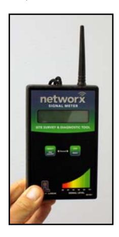
AL-NSM Networx Signal Meter
Performs a site survey test of the premises to:
- find the optimum location for Networx Gateways relative to Networx locks
- find the optimum location for Networx locks relative to Networx Gateways
- determine the optimum number of Networx Gateways required to cover the signal area of the Networx locks you plan to install
- perform diagnostic testing of existing Networx Gateway radio signals within your installation environment
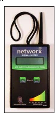
AL-NSM Signal Meter
Using the various available Modes, the AL-NSM (hereafter referred to as the " NSM ") can also measure radio noise levels, calculate overall signal quality, discover Networx locks not yet assigned to Gateways, and even send a "locate" signal (causing all unassigned locks to "beep").
Depending on how you use the NSM (see the " TYPICAL SCENARIOS " section), the NSM can work by itself, in conjunction with DL-Windows (version 5.0 and later) and a Networx Gateway (version 3.91 and later) using the "Gateway Signal Test Mode" feature in DL-Windows or with the AL-NSG Networx Signal Generator , explained below. Note: For more information about the "Gateway Signal Test Mode" feature, see OI383 DL-Windows for Networx User's Guide .
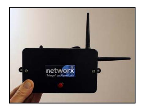
AL-NSG Networx Signal Generator
As mentioned above, the NSM Signal Meter may be used
with either an existing operational Gateway or the portable AL-NSG Networx Signal Generator . The AL-NSG (hereafter referred to as the " NSG ") is a portable batterypowered Gateway simulation device that generates continuous Gateway radio signals to an NSM .
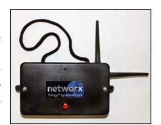
AL-NSG Signal Generator
Depending on how you use the NSG (see the " TYPICAL SCENARIOS " section), the NSG can be placed in the proposed location for a Networx Gateway or in the proposed location of a Networx lock, to determine the acceptability and the dependability of the radio sig-
nal coverage. The NSG can be mounted using the inert nylon lanyard or reusable adhesive mounting putty (supplied with the NSG ).
This manual does NOT contain preliminary information regarding your wireless Networx system, and only some of the many DL-Windows features that are
available are covered here. If you are unfamiliar with the terminology or operations described in this manual, stop here and read the two guides OI382 and OI383 (supplied with the DL-Windows software) cited above before proceeding.
POWER ON / OFF
NSM Signal Meter
- To power on: With the 9V battery installed, simply press and release the left SELECT button. Note: The unit automatically turns off after 20 minutes.
- To power off: Press and hold the left SELECT button for 10 seconds.
NSG Signal Generator
- To power on: With both 9V batteries installed, simply press and release the red ( ON/OFF ) button on the front cover (blue LED turns on). Note: The unit automatically turns off after 30 minutes.
- To power off: Press and hold the red ( ON/OFF ) button (blue LED turns on solid); when the blue LED turns off, immediately release the button.
Don't forget to read the USEFUL TIPS section on page 6 !

TABLE OF CONTENTS
| OVERVIEW1 |
|---|
| POWER ON / OFF1 |
| TYPICAL SCENARIOS2 |
| NSM MODE SELECTION3 |
| MODE DEFINITIONS3 |
| USEFUL TIPS6 |
| LOW BATTERY7 |
| SPECIFICATIONS7 |
| SIGNAL LEVEL TESTING CHART 8-11 |
| LIMITED WARRANTY12 |
TYPICAL SCENARIOS

First, determine HOW you want to use the NSM and/or the NSG by selecting a Scenario that best suits your situation. Then, depending on your answer, jump to the page describing the Mode you will use.
Scenario 1:
Where should I mount my Networx Gateway to obtain sufficient signal coverage for my Networx locks? (Locations / proposed locations for locks known).
Hang the NSG Signal Generator from the Networx lock lever handle, then hold the NSM Signal Meter in the proposed Gateway mounting location to verify sufficient signal strength between the two.
NSM Modes used in this scenario:
- 1. DL-WINDOWS LVL (page 3)
- 2. SIGNAL LVL dBm (page 3)
- 4. SIGNAL QUALITY (page 4)
Scenario 2:
I found an ideal mounting location for my Gateway, but will the Gateway signal coverage be sufficient to reach my (proposed) Networx lock locations?
Hang or stick the NSG Signal Generator in the exact Gateway installation location, then bring the NSM Signal Meter to the (proposed) Networx lock installation location to verify sufficient signal strength between the two.
NSM Modes used in this scenario:
- 1. DL-WINDOWS LVL (page 3)
- 2. SIGNAL LVL dBm (page 3)
- 4. SIGNAL QUALITY (page 4)
Scenario 3:
I want to add more locks to my existing Networx system (Gateways, Networx locks and DL-Windows). Will these new locks be in range of my (existing) Gateway(s)?
In DL-Windows, run the "Gateway Signal Test Mode" feature for the Gateway, then bring the NSM Signal
Meter to the (proposed) Networx lock installation location to verify sufficient signal strength between the two.
NSM Modes used in this scenario:
- 1. DL-WINDOWS LVL (page 3)
- 2. SIGNAL LVL dBm (page 3)
- 4. SIGNAL QUALITY (page 4)
For instructions regarding the "Gateway Signal Test Mode" feature, see OI383 DL-Windows for Networx User's Guide . Note: The NSG Signal Generator is not required for this scenario.
Scenario 4:
I am experiencing wireless connectivity issues with an existing Networx system (Gateways, Networx locks and DL-Windows). How can I troubleshoot these issues?
Verify sufficient signal strength between the existing Gateway and the existing Networx lock:
In DL-Windows, run the "Gateway Signal Test Mode" feature for the Gateway, then hang the NSM Signal Meter from the Networx lock lever handle and observe the number of missed packets displayed in the " SIGNAL QUALITY " Mode (see below, " 4. SIGNAL QUALITY ").
Test " NOISE LEVEL dBm " in the area:
Canvass the area between the existing Networx Gateway and the existing Networx lock while observing the " Noise Lvl dBm " reading on the NSM Signal Meter display.
NSM Modes used in this scenario:
- 3. NOISE LVL dBm (page 4)
- 4. SIGNAL QUALITY (page 4)
For instructions regarding the "Gateway Signal Test Mode" feature, see OI383 DL-Windows for Networx User's Guide . Note: The NSG Signal Generator is not required for this scenario.
Don't forget to read the USEFUL TIPS section on page 6 !

NSM MODE SELECTION
To cycle (scroll) through each Mode:
Press and hold the left SELECT button (keep pressed)…then press and release the right STEP button to step through each individual Mode.
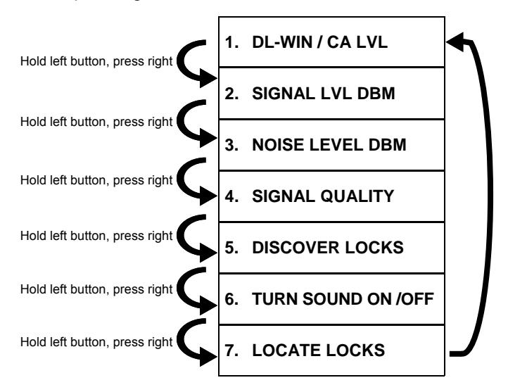
After " LOCATE LOCKS ", the selections repeat, starting again at " DL-WIN / CA LVL ". Note: The NSM powers down if you press and hold the left SELECT button for too long without pressing the right STEP button.
POOR FAIR GOOD EXCELLENT SIGNAL LEVEL CHART
Signal strength in "DL-Windows units" (Higher Number = Stronger Signal)
POOR = Intermittent communication (not recommended). FAIR = Useable, but occasional signal loss possible. GOOD = Fully acceptable signal level. EXCELLENT = Optimal signal level.
MODE DEFINITIONS
1. DL-WIN/CA LVL
Displays the signal strength received from a Networx Gateway or received from an NSG (in the same units / format displayed in DL-Windows or the CA3000 Card Access software; see SIGNAL LEVEL CHART ).
IMPORTANT: The higher the number, the stronger the signal.
When the test signal is generated via the DL-Windows "Gateway Signal Test Mode" feature:
- GTW RX = Signal level at which the Networx Gateway receives the NSM data transmission signal.
- LCK RX = Signal level at which the NSM receives the Networx Gateway data transmission signal.
TIP: In a normal working system, these two numbers should be fairly close in value; if the values differ by more than 10 to 12, there might an issue with the existing Networx Gateway.
When the test signal is generated via the NSG :
- GTW RX = Signal level at which the NSG receives the NSM data transmission signal.
- LCK RX = Signal level at which the NSM receives the NSG data transmission signal.
A typical NSM display in this Mode will look like this:
GTW Rx Sig 58 LCK Rx Sig 56
2. SIGNAL LVL dBm
This Mode is identical to the previous Mode, but expressed in dBm units (signal level relative to 1 milliwatt). It is provided for those more familiar with signal readings expressed using standard radio communication terminology.
DBm units are expressed in negative numbers; therefore the higher the negative number, the weaker the signal.
For example, a reading of -27 is stronger ("better") than -55.
A typical NSM display in this Mode will look like this:
GTW Rx dBm -40 LCK Rx dBm -38
See previous Mode for GTW RX and LCK RX definitions; to assist in visualizing dBm units, see the chart in the USEFUL TIPS section on page 6.
Don't forget to read the USEFUL TIPS section on page 6 !

3. NOISE LVL dBm
Displays the maximum and minimum background radio noise level in the installation environment, in dBm units.
"Noise" refers to unwanted radio signals that can "interfere" or obstruct the Networx radio signals.
The top line displays the current noise reading, and the bottom line displays the maximum and minimum noise levels received. To reset the display (all noise level readings) press and release the right RESET button.
TIP: Upon entering this Mode, we recommend immediately pressing the right RESET button, clearing any unintended noise level readings. To obtain realistic noise level readings, it is recommend to observe the results for several minutes, then reset (press and release the right RESET button) and repeat several times.
A typical NSM display in this Mode will look like this:
NOISE LEVEL -77 MIN-107 MAX- 56
Noise levels noisier than -85 (as readings move up to zero, for example -84, -83, -82, etc.), indicate unacceptable levels of noise.
The example above shows a current noise reading of - 77, which is noisier than the -85 limit. The lower the negative number (as readings move up to zero), the more noise detected by the NSM . Note: The integral sounder will chirp any time the noise level exceeds -85. Note: Be careful not to confuse normal Networx communication radio traffic with noise. In the example above, notice also the minimum noise -107 (quiet) and the maximum noise detected -56 (noisy) in the area.
TIP: Some locations may contain more radio noise than other locations. Computer rooms and electrical control panel utility closets are examples of locations that often contain high amounts of electrical noise, and should therefore be avoided.
IMPORTANT: When a Gateway is added to the Networx system, DL-Windows assigns the Gateway a specific channel number that determines the frequency for all subsequent communications between the Gateway and the Networx locks. The noise level readings may vary depending upon the channel number selected. Therefore, the proper channel MUST be set on the NSM to determine potential radio interference on that pre-set channel.
First, find the channel number assigned to the Networx Gateway in DL-Windows Gateway Configuration screen.
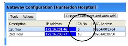
Channel Number shown in DL-Windows
Then, set the NSM channel number as follows:
Channel Selection Procedure
With the display showing the example above, to change and set the desired Gateway channel number (1 - 50), press and hold both buttons simultaneously , then release right STEP button and press again (repeatedly). When the desired channel number appears, release both buttons.
This mode can be helpful when walking around to find the source of where the noise is highest.
A typical NSM display will look like this:
CHANNEL # 12
General Noise Search
When you are unaware of the Gateway channel assigned to the Gateway by DL-Windows, or are looking for general noise during a site survey, we recommend scanning for noise on every tenth channel. For example, check for noise on channel 5, 15, 25, 35, etc.
TIP: If you determine there is noise in the area, it may be helpful to utilize this Mode to locate the source of the noise. While surveying the area, pay close attention to the Noise level readings to locate the peak / Max level able to be detected (lowest negative number).
Don't forget to read the USEFUL TIPS section on page 6 !

4. SIGNAL QUALITY
Displays the overall quality of the link between a Networx Gateway (or an NSG ) and the NSM . The link is defined by several measured factors, including the number of missed data packets, signal strength and consistency of the data.
A typical NSM display in this Mode will look like this:
LINK QUAL EXCEL MISSED PKTS 00
The options are displayed as " EXCEL " ("Excellent"), " GOOD ", " FAIR " and " POOR " (refer to chart on page 3).
The accumulation of missed packets will affect the link quality displayed. Occasional missed packets are common and are of no concern.
TIP: Upon entering this Mode, we recommend immediately pressing the right RESET button to clear any ambiguous missed data packets. To obtain realistic samples of data, it is recommend to keep physically still, observe the results for 1-2 minutes, then reset (press and release the right RESET button) and repeat several times.
5. DISCOVER LOCKS
This Mode attempts to discover then display the attributes of all locks that are "discoverable" (locks that are reset or not yet assigned to a Gateway) within the signal coverage area. This Mode simulates the routine action of discovering locks in DL-Windows.
Upon the release of the right STEP button, a typical NSM display will look like this:
SEARCHING… 07 FOUND
Note: This lock discovery process can be stopped at any time by pressing right STEP button, and only those locks found until that time will be returned.
After the lock discovery process ends, the display automatically changes to:
FOUND 07 LOCKS RT BTN TO VIEW
Press right STEP button to view each Networx lock's Serial number and signal level in DL-Windows units (where the higher the number, the stronger the signal):
# ID SIG 01 2AD50204 49
When many locks are found, you can scroll through the list of locks by pressing and releasing the right STEP button (the selections repeat after the last lock).
Note: The ID or lock Serial number is a unique 8 character factory designation affixed to each Networx lock housing and/or a yellow ID card included with each Networx lock.
Note: To exit this Mode (without performing another discovery) press the left SELECT button to return to Mode 1 (" DL-WIN/CA LVL ").
TIP: This mode can be especially helpful in verifying the status of your Networx locks. For example, if a previously assigned lock is discovered by the NSM , this Mode can prove this lock has lost its configuration and has likely been reset (lock requires reassignment to the Gateway to restart communications).
In addition, if your Gateway cannot discover an unassigned lock, you can use this discovery Mode to determine whether the NSM can discover it. If the NSM is unable to discover this lock, this indicates a potential internal issue with the Networx lock.
Don't forget to read the USEFUL TIPS section on page 6 !

6. TURN SOUND ON / OFF
While scrolling through the Mode selections and this Mode is reached, upon release of the left SELECT button, the sounder can be toggled on or off. For example, when the following is displayed:
SELECT MODE: TURN SOUND OFF
...release the left SELECT button and the sound will be turned off:
SOUND NOW OFF
The above example can also be used for the opposite (turning the sound ON).
Don't forget to read the USEFUL TIPS section on page 6 !

7. LOCATE LOCKS
This Mode allows you to locate any physical lock that is not currently assigned to a Gateway. When initiated, the NSM will send a locate command signal that will cause all of the unassigned locks within the signal coverage area to sound a "chirp" every second for a total of 45 seconds.
Upon the release of the right STEP button, a typical NSM display in this Mode will look like this:
LOCATE LOCKS UNASSIGNED ONLY
Upon release of the left SELECT button, the display will change to:
LOCATE CMD SENT PLEASE WAIT
After the command is broadcasted, the display will change to:
PRESS LEFT BTN TO CONTINUE
Note: To exit this Mode (without performing another locate lock command) press the left SELECT button to return to Mode 1 (" DL-WIN/CA LVL ").
TIP: This Mode is useful in testing the range limits of your installation, verifying that the radio inside each physical lock is operational, and if a lock is currently assigned to a Gateway (will chirp if unassigned). In addition, use this Mode with the " 5. DISCOVER LOCKS " Mode to help you find the lock(s) you just discovered.
USEFUL TIPS

Hand Placement
When holding either the NSM Signal Meter or the NSG Signal Generator , the human body itself can have an affect on the radio signals. Therefore, we recommend holding either unit from the bottom left corner (see photos) when measuring radio signals.
Averaging Signals
resent median values.
Advantage of Integral Sounder The integral sounder on the NSG provides simultaneous audible feedback during data transmissions. In addition, the opposite (loss of sound) provides immediate recognition of "null" areas where the signal is absent.
When attempting to evaluate radio signal quality, it is important to average the data provided by the NSM , regardless of which Mode is used. High traffic environments, radio interference, etc. may easily cause signal fluctuations, therefore it is recommended to take multiple readings over several minutes to ensure the results rep-
For example, in Mode 1, if the NSM is chirping and then suddenly silences at a specific location, that location may represent a null location, where the radio signal is lost entirely. In addition, in Mode 3, it is often helpful to use the sounder as an immediate warning of radio interference.
Unit Placement
To optimize results, it is crucial that the NSM or NSG (depending how they are used), be located / held within the inside ("protected" side) of the door (the actual location of the Networx lock internal radio). For example, if the NSM is hung on the outside ("unprotected" side) lever and the door is closed, the readings will be unreliable.
Lanyard vs Reusable "Mounting Putty"
Both the NSM Signal Meter and the NSG Signal Generator are equipped with an inert nylon lanyard intended to be used to hang the unit from a lever handle or other secure object. In addition, the NSG comes with reusable adhesive mounting putty that can be used to temporarily mount the unit to a wall or door, as needed.
Radio Signals and the Human Body
Radio signals bounce off of (or are absorbed by) almost everything, including the human body itself, having a positive or negative effect on the radio signal. Therefore, we recommend to enable the desired Mode and to walk several feet away from the unit to obtain an average result (see " Averaging Signals " below). Best results are obtained when the NSM or the NSG is hung or affixed, motionless, on or from the intended installation location (i.e. the lever handle of the intended installation door or the mounting location of the Gateway).
NSG Physical Dimensions
It is useful to note that the exact dimensions of the NSG is identical to a standard Networx Gateway (models AL-IME , AL-IM80211 , AL-IMEPOE and the AL-IMEPOEP ). Therefore when an optimal mounting location is found using the NSG , simply mark its side mounting hole tabs to greatly simplify the mounting of the permanent Gateway.
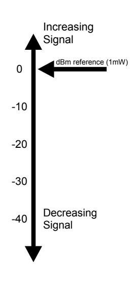
DBM Chart
Readings are provided in dBm units for those more familiar with using standard radio communication terminology. The chart at right is provided to assist in visualizing dBm units, especially the concept of how signal levels increase (grow stronger) as they move up the scale closer to zero.
This concept also applies to noise levels: As readings move up to zero, the noisier (worse) the noise levels become in the area.
LOW BATTERY
NSM Low Battery
When batteries are weak in the NSM , the following is displayed:
REPLACE BATTERY IN THIS UNIT
Replace 9 volt battery as soon as possible. Always use a fresh battery.
NSG Low Battery
When batteries are weak, the NSG transmits a low battery signal to the NSM , and the NSM displays the following:
REPLACE BATTERY IN TEST GATEWAY
IMPORTANT: Replace BOTH 9 volt batteries in the NSG as soon as possible. Always replace BOTH batteries at one time with two fresh batteries .
SPECIFICATIONS
NSM Networx Signal Meter
Power Source : 9VDC alkaline battery
(Duracell MN1604 or equiva-
lent)
Typical Battery Life : 30 hours, continuous
Dimensions (WxHxD) : 3½ x 5½ x 1¼ in.
(8.9 x 14 x 3.2 cm)
Shipping Weight : 9oz. (255g) approx.
Operating Temperature : 32° - 120°F (0° - 49°C)
NSG Networx Signal Generator
Power Source : Two 9VDC alkaline batteries.
(Duracell MN1604 or equiva-
lent)
Typical Battery Life : 100+ hours, continuous.
Dimensions (WxHxD) : 6 x 3⅝ x 1 9/16 in.
(15.3 x 9.2 x 4 cm)
Shipping Weight : 9.5oz. (269g) approx. Operating Temperature : 32° - 120°F (0° - 49°C)
| SIGNAL LEVEL TESTING CHART | |||||
|---|---|---|---|---|---|
| # |
Gateway
Location or MAC Address |
Door
Location or Serial # |
Signal
Level |
Remarks | |
| SIGNAL LEVEL TESTING CHART | ||||
|---|---|---|---|---|
| # |
Gateway
Location or MAC Address |
Door
Location or Serial # |
Signal
Level |
Remarks |
| SIGNAL LEVEL TESTING CHART | ||||
|---|---|---|---|---|
| # |
Gateway
Location or MAC Address |
Door
Location or Serial # |
Signal
Level |
Remarks |
| SIGNAL LEVEL TESTING CHART | ||||
|---|---|---|---|---|
| # |
Gateway
Location or MAC Address |
Door
Location or Serial # |
Signal
Level |
Remarks |
ALARM LOCK LIMITED WARRANTY
ALARM LOCK SYSTEMS, INC. (ALARM LOCK) warrants its products to be free from manufacturing defects in materials and workmanship for twenty four months following the date of manufacture. ALARM LOCK will, within said period, at its option, repair or replace any product failing to operate correctly without charge to the original purchaser or user.
This warranty shall not apply to any equipment, or any part thereof, which has been repaired by others, improperly installed, improperly used, abused, altered, damaged, subjected to acts of God, or on which any serial numbers have been altered, defaced or removed. Seller will not be responsible for any dismantling or reinstallation charges, environmental wear and tear, normal maintenance expenses, or shipping and freight expenses required to return products to ALARM LOCK. Additionally, this warranty shall not cover scratches, abrasions or deterioration due to the use of paints, solvents or other chemicals.
THERE ARE NO WARRANTIES, EXPRESS OR IM-PLIED, WHICH EXTEND BEYOND THE DESCRIPTION ON THE FACE HEREOF. THERE IS NO EXPRESS OR IMPLIED WARRANTY OF MERCHANTABILITY OR A WARRANTY OF FITNESS FOR A PARTICULAR PUR-POSE. ADDITIONALLY, THIS WARRANTY IS IN LIEU OF ALL OTHER OBLIGATIONS OR LIABILITIES ON THE PART OF ALARM LOCK.
Any action for breach of warranty, including but not limited to any implied warranty of merchantability, must be brought within the six months following the end of the warranty period.
IN NO CASE SHALL ALARM LOCK BE LIABLE TO ANY-ONE FOR ANY CONSEQUENTIAL OR INCIDENTAL DAMAGES FOR BREACH OF THIS OR ANY OTHER WARRANTY, EXPRESS OR IMPLIED, EVEN IF THE LOSS OR DAMAGE IS CAUSED BY THE SELLER'S OWN NEGLIGENCE OR FAULT.
In case of defect, contact the security professional who installed and maintains your security system. In order to exercise the warranty, the product must be returned by the security professional, shipping costs prepaid and insured to ALARM LOCK. After repair or replacement, ALARM LOCK assumes the cost of returning products under warranty. ALARM LOCK shall have no obligation under this warranty, or otherwise, if the product has been repaired by others, improperly installed, improperly used, abused, altered, damaged, subjected to accident, nuisance, flood, fire or acts of God, or on which any serial numbers have been altered, defaced or removed. ALARM LOCK will not be responsible for any dismantling, reassembly or reinstallation charges, environmental wear and tear, normal maintenance expenses, or shipping and freight expenses required to return products to ALARM LOCK. Additionally, this warranty shall not cover scratches, abrasions or deterioration due to the use of paints, solvents or other chemicals.
This warranty contains the entire warranty. It is the sole warranty and any prior agreements or representations, whether oral or written, are either merged herein or are expressly cancelled. ALARM LOCK neither assumes, nor authorizes any other person purporting to act on its behalf to modify, to change, or to assume for it, any other warranty or liability concerning its products.
In no event shall ALARM LOCK be liable for an amount in excess of ALARM LOCK's original selling price of the product, for any loss or damage, whether direct, indirect, incidental, consequential, or otherwise arising out of any failure of the product. Seller's warranty, as hereinabove set forth, shall not be enlarged, diminished or affected by and no obligation or liability shall arise or grow out of Seller's rendering of technical advice or service in connection with Buyer's order of the goods furnished hereunder.
ALARM LOCK RECOMMENDS THAT THE ENTIRE SYS-TEM BE COMPLETELY TESTED WEEKLY.
Warning: Despite frequent testing, and due to, but not limited to, any or all of the following; criminal tampering, electrical or communications disruption, it is possible for the system to fail to perform as expected. ALARM LOCK does not represent that the product/system may not be compromised or circumvented; or that the product or system will prevent any personal injury or property loss by burglary, robbery, fire or otherwise; nor that the product or system will in all cases provide adequate warning or protection. A properly installed and maintained alarm may only reduce risk of burglary, robbery, fire or otherwise but it is not insurance or a guarantee that these events will not occur. CONSEQUENTLY, SELLER SHALL HAVE NO LIA-BILITY FOR ANY PERSONAL INJURY, PROPERTY DAMAGE, OR OTHER LOSS BASED ON A CLAIM THE PRODUCT FAILED TO GIVE WARNING. Therefore, the installer should in turn advise the consumer to take any and all precautions for his or her safety including, but not limited to, fleeing the premises and calling police or fire department, in order to mitigate the possibilities of harm and/or damage.
ALARM LOCK is not an insurer of either the property or safety of the user's family or employees, and limits its liability for any loss or damage including incidental or consequential damages to ALARM LOCK's original selling price of the product regardless of the cause of such loss or damage.
Some states do not allow limitations on how long an implied warranty lasts or do not allow the exclusion or limitation of incidental or consequential damages, or differentiate in their treatment of limitations of liability for ordinary or gross negligence, so the above limitations or exclusions may not apply to you. This Warranty gives you specific legal rights and you may also have other rights which vary from state to state.