Alarm Lock AL-IME2-POE Power Over Ethernet Gateway Installation Instructions
Open the original PDF document
View PDF

AL-IME2-POE "Power Over Ethernet" Gateway Installation Instructions
345 Bayview Avenue, Amityville, New York 11701 For Sales and Repairs 1-800-ALA-LOCK For Technical Service 1-800-645-9440 or visit us at http://tech.napcosecurity.com/ (Note: Technical Service is for security professionals only) Publicly traded on NASDAQ Symbol: NSSC
© ALARM LOCK 2017 WI2152BLF 12/17
OVERVIEW
The AL-IME2-POE is a "Power Over Ethernet" Gateway device used within the Trilogy Networx™ wireless system. Installation is simple, with the AL-IME2-POE only requiring access to one RJ-45 Ethernet network cable.
Version 2
The AL-IME2-POE "version 2" Gateways (notice the " 2 " in the model name) are the next generation of Networx Gateways. The "version 2" models are virtually the same as the original "version 1" Gateways, but have the added ability to expand your system with up to 7 Expanders (model AL-IME2-EXP Expanders cannot communicate with older "non-version 2" Gateways). Note: Version 2 Gateways CAN be mixed into an existing system that includes older "non-version 2" Gateways.
IMPORTANT: DL-Windows version 5.4.2 or later is required to support version 2 Gateways and Expanders.
The AL-IME2-POE Gateway is compatible with Alarm Lock and Continental Access products. Refer to the documentation supplied with your software for integration details.
Blue ID Card
We strongly recommend that when installing any model Gateway, a blue-colored "Gateway ID Card" (OI357) be completed. Gateway physical locations may easily be forgotten. These ID cards may prove very useful when replacing Gateways, when selecting a particular Gateway to use to discover locks, or whenever an installed Gateway needs to be physically located.
AL-IME2-POE SPECIFICATIONS NETWORK RANGE
Gateway to Locks: Clear field range 500'.
Typical indoor range: Networx 75-175'; ArchiTech
Networx 50 -125'.
Gateway / Expander to Expander: Clear field range 500'. Typical indoor range: 75-175'. Note: Actual range varies with building construction.
AL RADIO LINK
900 MHz GFSK 50 Channels 10mW power output
POWER - Installer should use a UL or ETL Listed POE injector or
a UL or ETL Listed POE switch. POE Voltage: 48VDC Nominal Input Voltage: 5 - 6VAC
ENVIRONMENTAL
Operating Temperature: -20˚ to 60˚C (-4˚ to 140˚F) Storage Temperature: -40˚ to 85˚C (-40˚ to 185˚F)
PHYSICAL
Enclosure Size: 4.5"H x 6.0"W x 1.94"D
Weight: 0.5lbs.
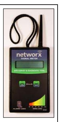
The AL-NSM Networx Signal Meter tool can help you perform a site survey test of the premises to find the optimum location for Gateways relative to Networx locks; as well as determine the optimum number of Gateways (or Expanders) needed for signal area coverage. See WI2092 or speak to your Alarm Lock sales representative for more information. TIP
GATEWAY LOCATION GUIDELINES
Before selecting a final mounting location for your Gateway, the following must be taken into consideration:
-
Gateways should be located within 175 feet (radially) from the intended wireless lock locations
- Open areas will increase range while concrete building construction, walls, ceilings and narrow corridors will decrease range
- ArchiTech series locks generally have shorter range to/from a Gateway
- Generally, the Gateway should be within approximately 75 feet (radially) from an AL-IME2-EXP Expander (see WI2156)
- Select a location that allows access to an RJ-45 network Ethernet cable connection
-
Gateways should be mounted in elevated areas; however mounting in a drop ceiling can adversely affect signal strength
- Preferred mounting position = 6 to 12" below standard 8-9 foot ceiling
- Gateways must be mounted vertically; horizontal "flat" mounting should be specifically avoided
- Although wood and wallboard construction can have little effect upon signal strength, concrete or brick can reduce signal strength by up to 35%. Steelreinforced concrete or metal lath and plaster can reduce signal strength as much as 90%!
- Do NOT mount close to electrical wiring or other metal obstructions such as pipes or conduits
- Installing in computer closets or server rooms can negatively impact signal strength
Helpful Tips
- In difficult installations wherein signal problems exist, the use of (multiple) AL-IME2-EXP Expanders throughout the premises is recommended. AL-IME2-EXP Expanders extend the coverage area of version 2 Gateways, allowing control of up to its rated maximum of 63 locks. Up to 7 Expanders can be added to one version 2 Gateway. For more information, see WI2156.
- We recommend obtaining or creating a layout of your intended system identifying all proposed installation locations, also noting building construction materials to assist in determining optimal Gateway installation locations
IMPORTANT: If you plan to use AL-IME2-EXP Expanders with your Gateway, be sure to read the " EXPANDER GROUP" DIALS section on page 3 before powering your Gateway.
The above guidelines and tips should be followed for each additional Gateway added to the system.
MOUNTING INSTRUCTIONS
The AL-IME2-POE rear housing must be mounted "up" as shown on the page 7 template; i.e. when the front housing is attached, its engraved Networx logo must be located at the lower right with the front housing positioned "up" in a conventional manner (the unit contains internal antennas that must be positioned vertically). Horizontal "flat" mounting of the enclosure is to be specifically avoided. As stated previously, the AL-IME2-POE Gateway only requires connection to an RJ-45 network Ethernet cable.
Mount as follows:
1. Insert a small flat-head screwdriver into the slots at the bottom and twist while applying inward pressure
(see Fig. 1; insert the screwdriver closer to the edges of the unit, as shown in the Fig. 1 "inset" image).
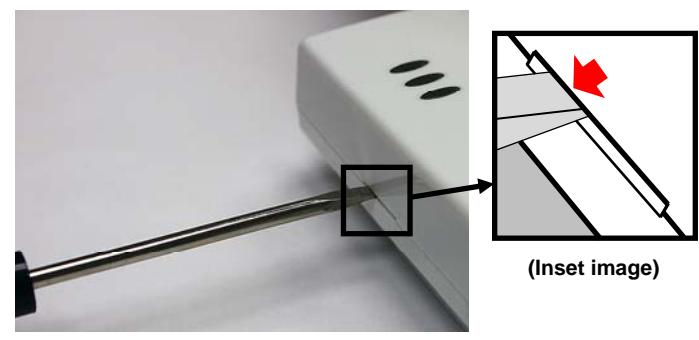
Fig. 1: To separate rear housing from cover (Inset: Insert flat-head screwdriver closer to the edges of the unit)
2. Using the rear housing as a mounting template, secure the unit to a wall or other flat surface using the hardware provided (see page 7 for printed template).
Shown in Fig. 2, the rear housing includes two mounting holes for single-gang ( A ) and four mounting holes for double-gang ( B ) electrical utility boxes, as well as four all-purpose holes ( C ) for mounting to drywall or other surfaces (use minimum #6 screws suitable for the surface).
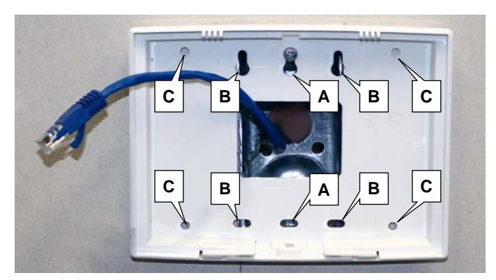
Fig. 2: Rear housing mounting holes for single-gang (A) and double-gang (B) electrical boxes, and four all-purpose holes (C)
CONNECTING TO A NETWORK
The AL-IME2-POE Gateway requires a connection from its Ethernet socket to a POE switch, router or injector using an RJ-45 cable (not a crossover cable). Upon connection, the Gateway automatically begins searching for a valid IP address from the network (see the POWER UP section on page 4).
IMPORTANT: Gateways can ONLY be discovered by DL-Windows when the PC running DL-Windows is on the same subnet as the Gateway. Refer to Subnet section for more information.

The following sub-sections refer to the DL-Windows software, therefore the following terminology may be better understood by referencing Ol383 (included with your Gateway).
Static IP Addresses
We recommend using static IP addresses for each Gateway:
- DL-Windows software performs faster; no wasted time re-locating Gateways that have had their IP addresses changed by DHCP
- Static IP addresses allow operation across subnets in large corporate networks (such as those that exist between buildings)
- Static IP addresses allow Emergency Commands (such as "Emergency Lockdown") to perform properly
Contact the Network Administrator
If you know the Gateway will be installed on a large corporate network that includes multiple subnets, we recommend you start by contacting the corporate network administrator and request the following:
- IP Address An address for each Alarm Lock Gateway device
- Subnet Mask Filtering data ("mask bits") as required by the aforementioned IP address
- Default Gateway The address of the physical device, such as a router, for the current subnet to which DL-Windows will be connected
Subnets
To improve security and processing performance, corporate networks are often divided into interconnected but separate "subnet" segments. The network administrator may decide to use routing tables or may specify blocks of addresses through which the two subnets can freely communicate in both directions. However, if the two subnets cannot freely communicate as in the illustration below, in order to communicate to the Gateway across the subnet, follow the steps below:
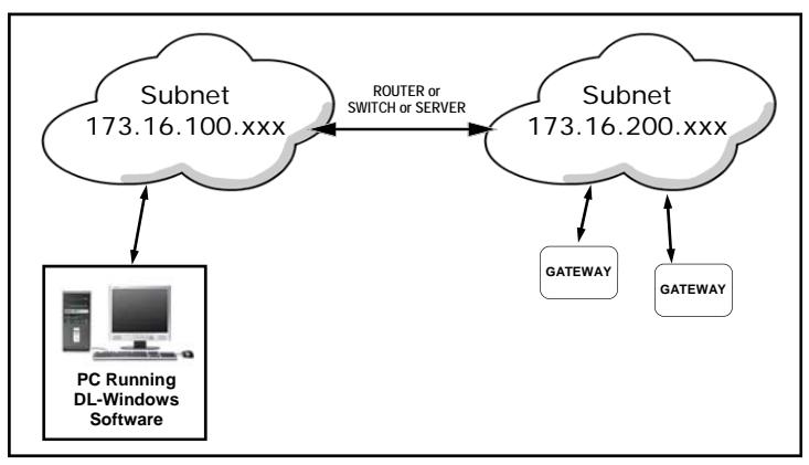
Fig. 3: Gateways on different subnets within a network
- Connect the Gateway to local network (DL-Windows on same subnet); Gateway receives valid IP address
- Using DL-Windows, Discover and add the Gateway to an Account
- Configure Gateway with the static IP address information of the subnet you plan to communicate with
- Disconnect from the local network remove power from the Gateway (Gateway will retain static IP information)
- Re-connect / re-apply power in the desired location / subnet
"EXPANDER GROUP" DIALS
Inside the Gateway are 2 rotary dials (see Fig. 4). These dials are used to set the "Expander Group" when you wish to add AL-IME2-EXP Expanders in your system (all AL-IME2-EXP Expanders include an identical set of dials). Therefore, the dial values set on your Gateway MUST then match the dial values set on your AL-IME2-EXP Expanders. IMPORTANT: Each Gateway in your system MUST be set to a different "Expander Group" value along with its associated Expanders. The "Expander Group" dial setting determines which Expanders are associated with which Gateway, thus preventing Gateways from discovering unintended Expanders. See WI2156 for more information about installing AL-IME2-EXP Expanders in your system.
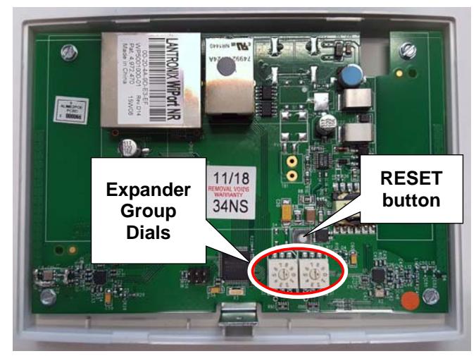
Fig. 4: "RESET" button and two "Expander Group dials"
Expander Group values of "00" through "99" are valid selections.
IMPORTANT: The small "selection arrow" on each dial must be pointing directly to the desired Group value. In Fig. 5 (below), the Group value is set to "50". Use a small flat-head screwdriver to turn the dials and make the selections. Be sure to orient the Gateway as shown above with the RESET button ABOVE the dials to ensure proper Group setting!
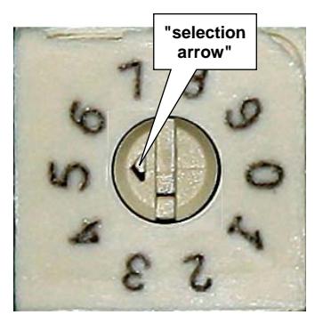
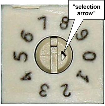
Fig. 5. Example: The above Expander Group dials are set to "50"
POWER UP
Connect RJ-45 (POE) Ethernet cable to the Gateway. Upon connection, the Gateway automatically begins searching for a valid IP address from the network.
Valid IP Address - LED Indication
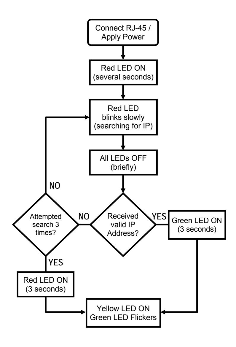
Upon power up, watch the 3 LEDs on the Gateway cover carefully to determine if the Gateway receives a valid IP address. Be patient; this process could take up to 1 minute. After applying power, the Red LED will blink slowly while searching for an IP address.
- If the GREEN LED turns on solid for 3 seconds , the Gateway received a valid IP address from the network! The Yellow LED will turn on solid and the Green LED will flicker indicating the Gateway is ready for Discovery by DL-Windows (not configured).
- If the RED LED turns on solid for 3 seconds (after 3 attempts to receive an IP address from the network), the Gateway was unable to receive a valid IP address from the network. However, the Yellow LED will still turn on solid and the Green LED will still flicker. Do not confuse this with the above valid IP address indication .
Refer to the flowchart for a visual representation of the above process:
Next, reset the Gateway as follows:
Reset the Gateway
IMPORTANT: Before securing the Gateway housing cover, ALWAYS reset the Gateway memory, even if the Gateway is new "out of the box" and/or has never been used previously.
After initial power up, press and hold the RESET button (see below for location); continue to hold the button until the red LED turns on solid. Now, release the button and the green LED will flicker rapidly.
Always reset the Gateway for new installations; you
can also reset the Gateway any time after the Gateway is powered. Two levels of reset exist, a "Normal" reset and "Factory" reset, as follows:
Normal Reset: Clears Gateway memory and user data allowing for re-discovery by DL-Windows. Press and hold the RESET button until the Red LED turns on solid, then release the button and the Green LED will start to flicker rapidly.
Factory Reset: Clears Gateway memory, user data and configuration data (such as static IP information), thus returning the unit to its original factory settings. Press and hold the RESET button, the Red LED turns on solid; keep holding until the Yellow LED also turns on solid. Release the button; the Yellow LED will remain on solid, and the Green LED will start to flicker rapidly, indicating a full factory reset.
Note: Resetting the Gateway (Normal or Factory) does NOT cause the Gateway to search for a new IP address. After a reset, power cycle the Gateway to initiate a new IP search .
GATEWAY LED INDICATIONS
| Yellow | Receiver On (normal operation) |
|---|---|
| Red | Transmitter On |
| Green | (Gateway Status) |
| Not configured - Rapid blinking / flickering | |
| Idle / configured - 1 blink per second | |
|
Lock Communication Fail - 2 blinks
(continuously) |
|
|
Expander Communication Fail - 4 blinks
(continuously) |
CLOSE HOUSING COVER
Close the housing cover by first engaging the hooks at the top, then snapping the bottom together. Secure the cover with the Bottom Screw provided as shown in Fig. 6.
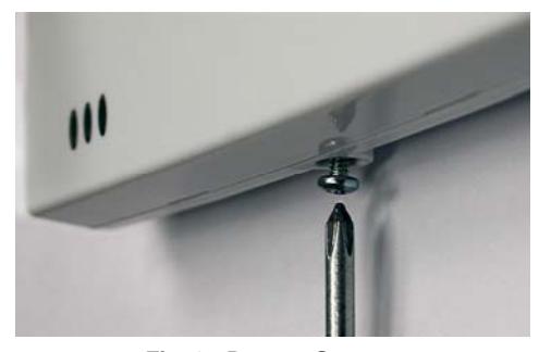
Fig. 6: Bottom Screw
Congratulations! You're finished! Now go to the DL-WINDOWS™ for Networx™ V5 USER'S GUIDE (OI383) for instructions about discovering your Gateway from DL-Windows.
NOTES
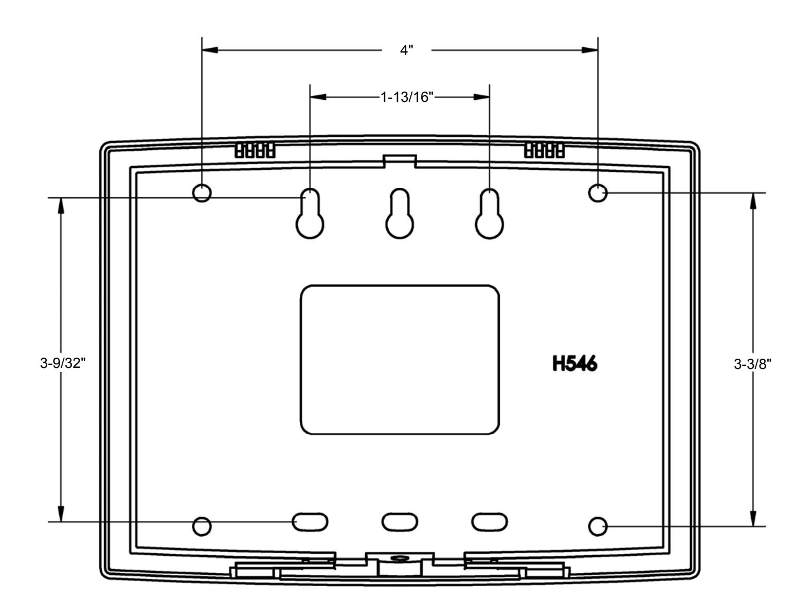
AL-IME2-POE Mounting Template
ALARM LOCK LIMITED WARRANTY
ALARM LOCK SYSTEMS, INC. (ALARM LOCK) warrants its products to be free from manufacturing defects in materials and workmanship for twenty four months following the date of manufacture. ALARM LOCK will, within said period, at its option, repair or replace any product failing to operate correctly without charge to the original purchaser or user.
This warranty shall not apply to any equipment, or any part thereof, which has been repaired by others, improperly installed, improperly used, abused, altered, damaged, subjected to acts of God, or on which any serial numbers have been altered, defaced or removed. Seller will not be responsible for any dismantling or reinstallation charges, environmental wear and tear, normal maintenance expenses, or shipping and freight expenses required to return products to ALARM LOCK. Additionally, this warranty shall not cover scratches, abrasions or deterioration due to the use of paints, solvents or other chemicals.
THERE ARE NO WARRANTIES, EXPRESS OR IM-PLIED, WHICH EXTEND BEYOND THE DESCRIPTION ON THE FACE HEREOF. THERE IS NO EXPRESS OR IMPLIED WARRANTY OF MERCHANTABILITY OR A WARRANTY OF FITNESS FOR A PARTICULAR PUR-POSE. ADDITIONALLY, THIS WARRANTY IS IN LIEU OF ALL OTHER OBLIGATIONS OR LIABILITIES ON THE PART OF ALARM LOCK.
Any action for breach of warranty, including but not limited to any implied warranty of merchantability, must be brought within the six months following the end of the warranty period.
IN NO CASE SHALL ALARM LOCK BE LIABLE TO ANY-ONE FOR ANY CONSEQUENTIAL OR INCIDENTAL DAMAGES FOR BREACH OF THIS OR ANY OTHER WARRANTY, EXPRESS OR IMPLIED, EVEN IF THE LOSS OR DAMAGE IS CAUSED BY THE SELLER'S OWN NEGLIGENCE OR FAULT.
In case of defect, contact the security professional who installed and maintains your security system. In order to exercise the warranty, the product must be returned by the security professional, shipping costs prepaid and insured to ALARM LOCK. After repair or replacement, ALARM LOCK assumes the cost of returning products under warranty. ALARM LOCK shall have no obligation under this warranty, or otherwise, if the product has been repaired by others, improperly installed, improperly used, abused, altered, damaged, subjected to accident, nuisance, flood, fire or acts of God, or on which any serial numbers have been altered, defaced or removed. ALARM LOCK will not be responsible for any dismantling, reassembly or reinstallation charges, environmental wear and tear, normal maintenance expenses, or shipping and freight expenses required to return products to ALARM LOCK. Additionally, this warranty shall not cover scratches, abrasions or deterioration due to the use of paints, solvents or other chemicals.
This warranty contains the entire warranty. It is the sole warranty and any prior agreements or representations, whether oral or written, are either merged herein or are expressly cancelled. ALARM LOCK neither assumes, nor authorizes any other person purporting to act on its behalf to modify, to change, or to assume for it, any other warranty or liability concerning its products.
In no event shall ALARM LOCK be liable for an amount in excess of ALARM LOCK's original selling price of the product, for any loss or damage, whether direct, indirect, incidental, consequential, or otherwise arising out of any failure of the product. Seller's warranty, as hereinabove set forth, shall not be enlarged, diminished or affected by and no obligation or liability shall arise or grow out of Seller's rendering of technical advice or service in connection with Buyer's order of the goods furnished hereunder.
ALARM LOCK RECOMMENDS THAT THE ENTIRE SYS-TEM BE COMPLETELY TESTED WEEKLY.
Warning: Despite frequent testing, and due to, but not limited to, any or all of the following; criminal tampering, electrical or communications disruption, it is possible for the system to fail to perform as expected. ALARM LOCK does not represent that the product/system may not be compromised or circumvented; or that the product or system will prevent any personal injury or property loss by burglary, robbery, fire or otherwise; nor that the product or system will in all cases provide adequate warning or protection. A properly installed and maintained alarm may only reduce risk of burglary, robbery, fire or otherwise but it is not insurance or a guarantee that these events will not occur. CONSEQUENTLY, SELLER SHALL HAVE NO LIA-BILITY FOR ANY PERSONAL INJURY, PROPERTY DAMAGE, OR OTHER LOSS BASED ON A CLAIM THE PRODUCT FAILED TO GIVE WARNING. Therefore, the installer should in turn advise the consumer to take any and all precautions for his or her safety including, but not limited to, fleeing the premises and calling police or fire department, in order to mitigate the possibilities of harm and/or damage.
ALARM LOCK is not an insurer of either the property or safety of the user's family or employees, and limits its liability for any loss or damage including incidental or consequential damages to ALARM LOCK's original selling price of the product regardless of the cause of such loss or damage.
Some states do not allow limitations on how long an implied warranty lasts or do not allow the exclusion or limitation of incidental or consequential damages, or differentiate in their treatment of limitations of liability for ordinary or gross negligence, so the above limitations or exclusions may not apply to you. This Warranty gives you specific legal rights and you may also have other rights which vary from state to state.