Alarm Lock AL-APB Auxiliary Power Booster User’s Guide
Open the original PDF document
View PDF

AL-APB Auxiliary Power Booster 345 Bayview Avenue, Amityville, New York 11701 USER'S GUIDE For Sales and Repairs 1-800-ALA-LOCK
For Technical Service 1-800-645-9440 or visit us at http://tech.napcosecurity.com/ (Note: Technical Service is for security professionals only) Publicly traded on NASDAQ Symbol: NSSC © ALARM LOCK 2019
OI403.aLF 5/19
DESCRIPTION
The AL-APB Auxiliary Power Booster is designed to unlock and allow entry into an ArchiTech series door lock that is unresponsive due to low batteries, dead batteries or an inoperative proximity reader.
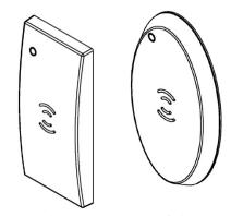
RECTANGULAR / OVAL PROXIMITY READER
The AL-APB works by reading and storing the proximity data of a valid cre-
dential and sending this data to the lock. Simply present a valid proximity credential to the AL-APB reader, place the front of the unit on the existing proximity reader and press a button. The AL-APB sends the proximity data while simultaneously powering the lock with its inductive Power Adapter (install the appropriate Power Adapter, either oval or rectangular, to fit the shape of the existing proximity reader on the door). Always install the Power Adapter such that it can be placed on the bottom edge of the proximity reader, as shown:
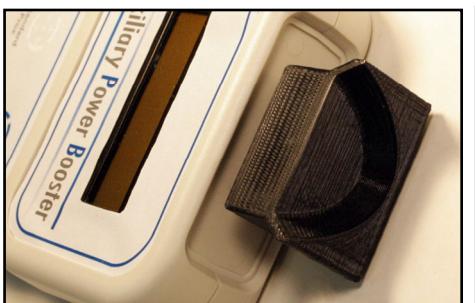
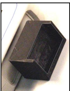
Install the Power Adapter so it can be placed on the bottom edge of the proximity reader (Oval shown at left, Rectangular at right)
REQUIREMENTS
The AL-APB requires two items:
- Four (4) AA batteries; use lithium batteries for longer life
- A valid proximity credential previously enrolled into the ArchiTech lock
TURNING ON / OFF
- Turn on: Press / release the left button.
- Turn off: Press and hold the left button for 5 seconds.
PLACE CARD ON PROPER TARGET (must appear)
Note: The above text must appear before the unit can be powered down. If the unit is "SENDING DATA...", simply press/release the right button, and the "PLACE CARD ON PROPER TARGET" will appear, then you can
press and hold the left button for 5 seconds to power off. Note: The AL-APB will automatically power off after about 15 minutes of non-use.
UNLOCK A DOOR
The AL-APB is equipped with left and right buttons and a 2-line LCD display to help guide you. Note: Before you begin, we recommend having the valid proximity credential in hand . To unlock an unresponsive door lock:
- 1. Insert either the oval or rectangular Power Adapter into the front of the AL-APB (see images at left).
- 2. Wake up the AL-APB : Press / release the left button.
PLEASE WAIT
AUXILIARY POWER BOOSTER
PLACE CARD ON PROPER TARGET
3. Present a valid credential to the reader located on the face of the unit. Be sure to hold the credential over the proper type, either " Standard " or " Smart " and listen for the double-chirp (indicates a successful read).
PROX DATA READ 000553A0F690 36
HOLD BOOSTER AGAINST READER
4. Simply place the Power Adapter flush against the bottom edge of the proximity reader. Observe the display:
SENDING DATA CHECK DOOR
Listen for the lock to unlock (it may take up to 1 minute for the lock to change its state). Open the door as soon as you hear the lock unlock.
If the following text appears but the lock does not unlock.
PROCESS COMPLETE
Press the right button to retry. If still not successful, wait 1-1½ minutes, and try again.
ADVANCED SETTINGS
DO NOT CHANGE these power and/or voltage settings except under the guidance of Alarm Lock Technical Support at 1-800-645-9440. To access the advanced settings:
1. Power the unit: Press and release the left button...
PLEASE WAIT AUXILIARY POWER BOOSTER V 1.7
2. When the version number is displayed, quickly press and hold BOTH buttons simultaneously...
CUSTOM SETUP
3. When the display reads CUSTOM SETUP, release both buttons.
SELECT MODE Hold Lft,Step Rt
4. When the display reads SELECT MODE, you have successfully accessed the advanced settings.
The above "SELECT MODE" screen will conveniently remain unchanged until you make your selections; otherwise the unit will time out and power down after about 15 minutes if you do not interact with the unit.
5. To step through each item, press and hold the left button, and press/release the right button. The items will repeat, as follows:
RF Power Voltage Setup Reset All Exit Setup
To select an item, simply release the left button.
For example, if you select the first item, "RF Power", the display will indicate your selection:
RF Power Hold Lft,Step Rt
To scroll through each setting within each item, press and hold the left button, and press/release the right button. Note: Selections with "**" asterisks = factory default setting. The available settings for each item are:
| RF Power | Voltage |
|---|---|
| -30 dBm | 50 Volts |
| -20 dBm ** | 75 Volts |
| -15 dBm | 100 Volts |
| -10 dBm | 125 Volts |
| -6 dBm | 150 Volts |
| 0 dBm | 175 Volts |
| +10 dBm | 200 Volts ** |
| 250 Volts |
Note: The dBm units (signal level relative to 1 milliwatt) is provided for those more familiar with signal readings expressed using standard radio communication terminology. The dBm units are expressed in negative numbers; therefore the higher the negative number, the weaker the signal. For example, a reading of -20 is stronger than -30.
The two other items include " Reset All " and " Exit Setup ". To reset all selections in all items back to their factory default settings (i.e. RF Power = -20 Dbm , Voltage = 200 Volts ), when Reset All appears, release the left button.
SELECT MODE Reset All
Defaults Loaded
To exit advanced settings, when Exit Setup appears, release the left button.
SELECT MODE Exit Setup
PLACE CARD ON PROPER TARGET
To proceed at this point, see " UNLOCK A DOOR " on the previous page.
SPECIFICATIONS
Power Source ............................. Four AA-size batteries. (Energizer "Ultimate" Lithium strongly recommended. Duracell Alkaline MN1500 may be used for a short period of time)
Typical Battery Life ................... 100 or more uses with Energizer "Ultimate" Lithium batteries. Note: If batteries are weak, "REPLACE BATTERIES IN THIS UNIT" will display. Replace with fresh batteries as soon as possible.
Dimensions (WxHxD) ................ 4 x 9½ x 1¼ inches ..................................................... (10.2 x 24 x 3.2 cm) Operating Temperature ............. 32°-120°F (0°-49°C) Weight ......................................... 16.6oz. (470g) approx, with batteries.