Alarm Kit Instructions i-ed01181_rev2
Open the original PDF document
View PDF

DEVICES COVERED IN THIS DOCUMENT:
- 4940 Alarm Kit (ALT, ALM, ALL)
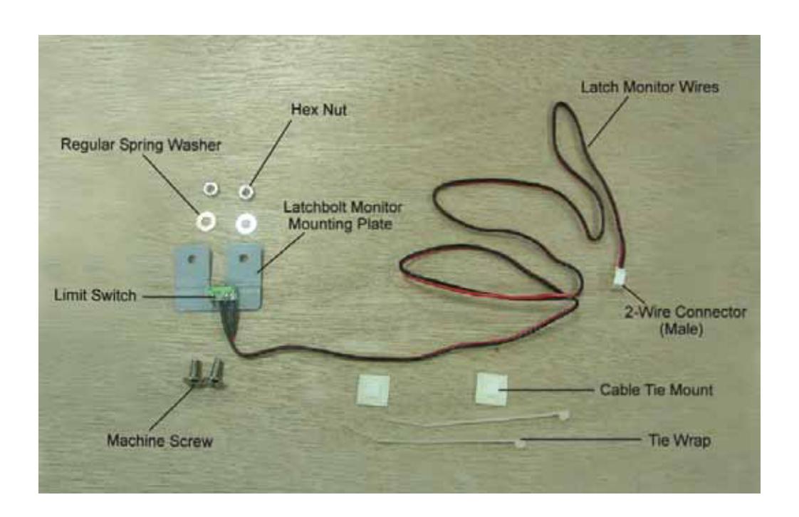
- 2-649-0168 Latch Monitor Switch
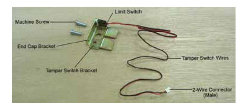
- 2-649-1090 Tamper Switch
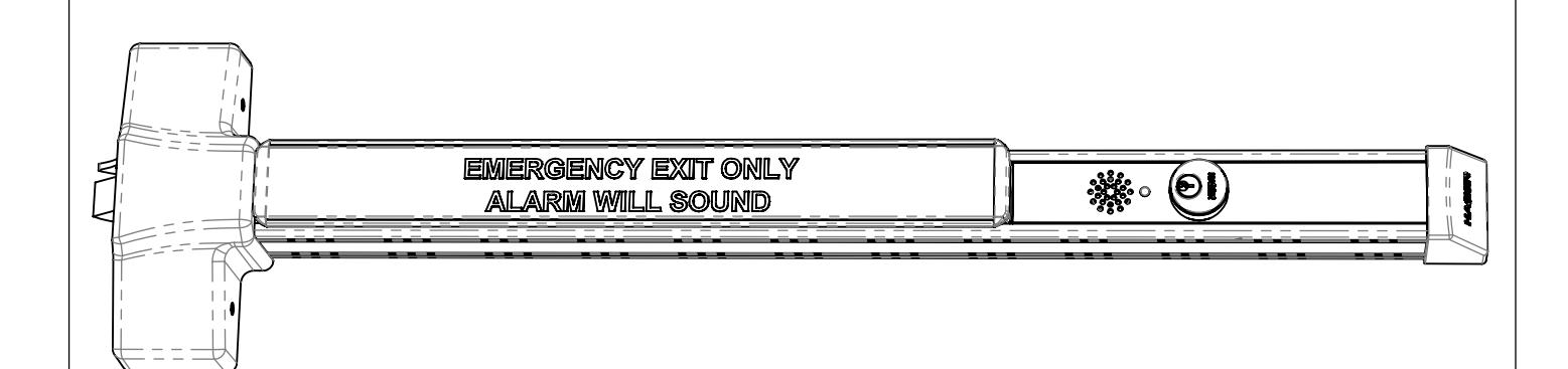
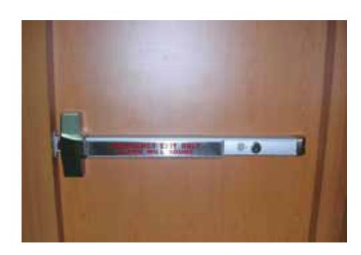
OVERVIEW

INSTALLING ALARM KIT
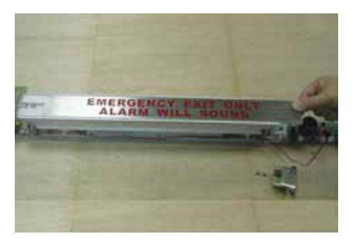
STEP ONE
STEP FOUR
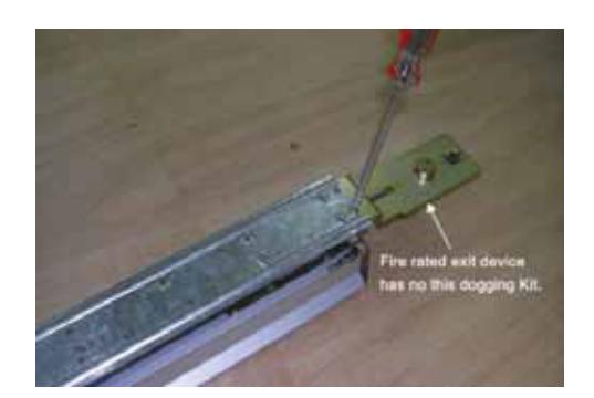
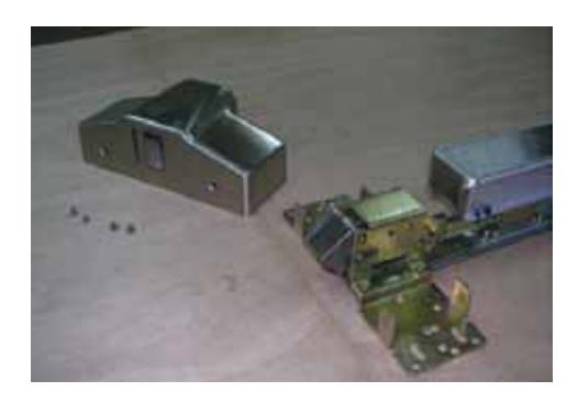
Disassemble device if it was installed on door. Remove dogging cover plate.
Turn device over and release two fixing screws of dogging kit.
STEP TWO
STEP FIVE
Remove head cover from device chassis.
Mount alarm kit on same position with dogging kit.

STEP THREE
Note: If installing the latch monitor switch, refer to page 6. If not, continue to Step 6.
Remove device mechanism housing.
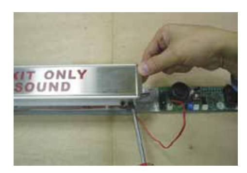
STEP SIX

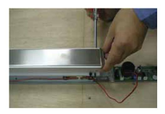
Release two fixing screws of push bar end cap.

STEP SEVEN
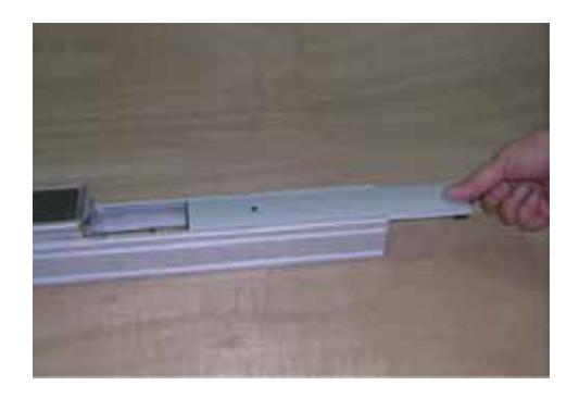
Slide push bar trim plate out of push bar.
STEP TEN
Slide mechanism housing back onto device.
STEP EIGHT
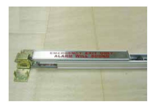
Slide in provided push bar trim plate with red printed cautionary note.
STEP ELEVEN
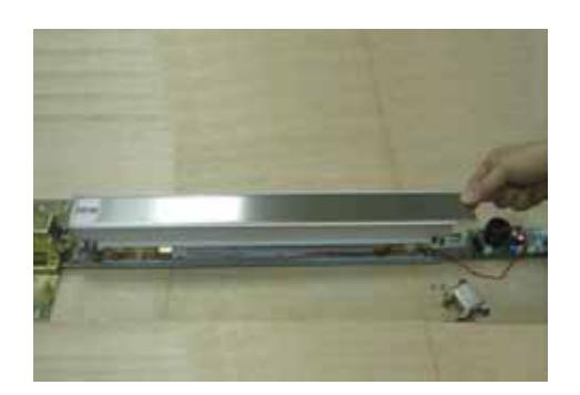
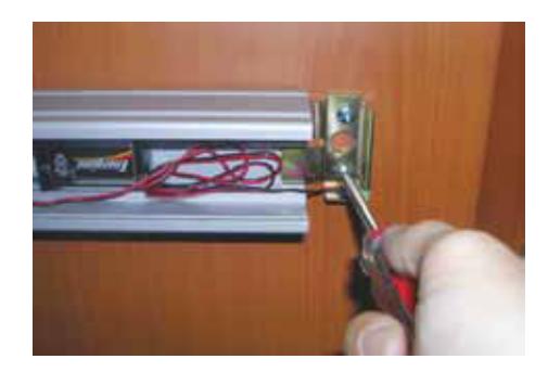
Install switch support plate and tighten by a switch nut.
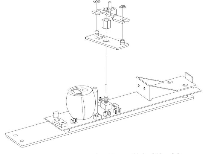
STEP NINE
Mount push bar end cap back.
Note: If installing tamper switch, refer to page 8. If not, continue to Step 10.
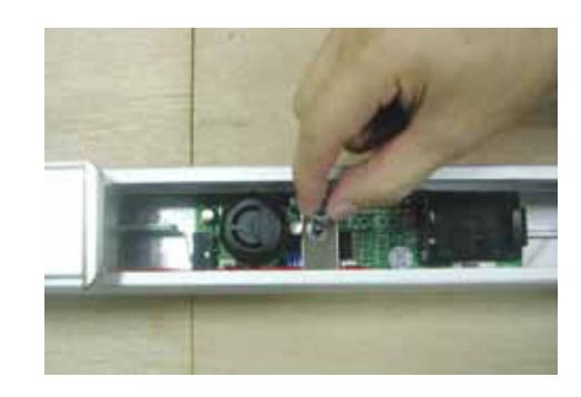

STEP TWELVE
Put one 9V lithium battery into battery housing as shown.
GENERAL INSTALLATION INSTRUCTIONS
| STEP ONE | STEP THREE |
|---|
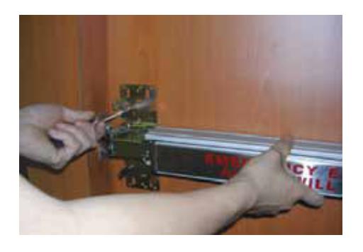
Install finished alarm device on door. For more details, see installation instructions and templates.

STEP TWO
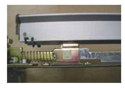
Install tamper switch bracket and end cap bracket together at same position.
Note: If not installing tamper switch, install standard end cap bracket.
STEP FOUR
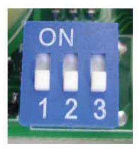
Set a length of alarm time on DIP switch.
To sound alarm for 1 minute, push Lever 1 to ON position.
To sound alarm for 3 minutes, push Lever 2 to ON position.
To sound alarm for 5 minutes, push Lever 3 to ON position.
To sound alarm continuously, push all levers to OFF position (factory default).

STEP FIVE
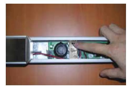
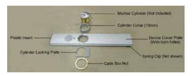
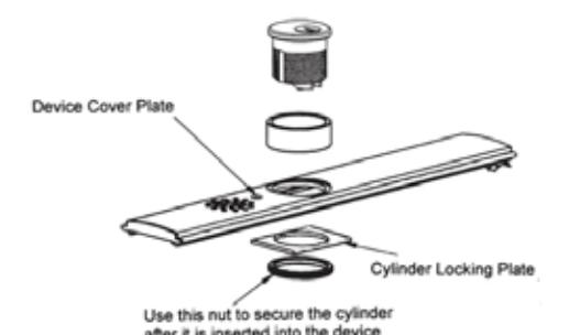
Install cylinder on provided device cover plate that has horn holes. Slide it onto device.
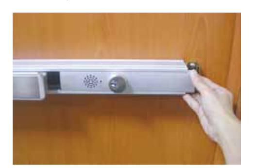
STEP SIX
Mount head cover and end cap, if removed.

INSTALLING LATCH MONITOR SWITCH
STEP ONE STEP TWO
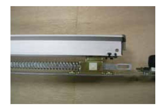
Turn device over and release two fixing screws as shown.
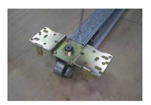
Place latchbolt monitor mounting plate here.

STEP THREE
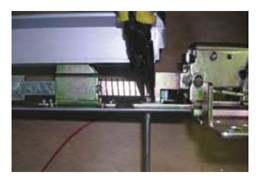
Use two mounting holes to install latchbolt monitor plate as shown.
STEP SIX
Stick second cable tie mount as shown.
STEP FOUR
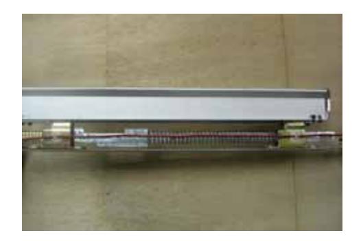
Secure latchbolt monitor plate with hex nuts and spring washers on both sides.
STEP SEVEN
Tighten latchbolt monitor wires by tie wraps on two cable tie mounts.
STEP FIVE
Stick one cable tie mount as shown.
STEP EIGHT
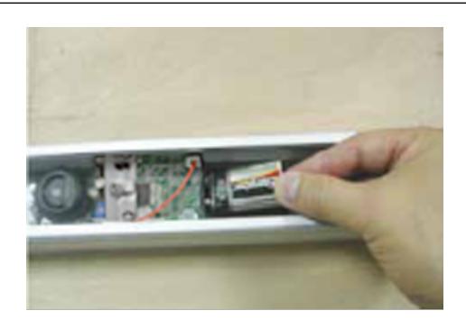
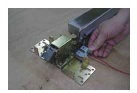
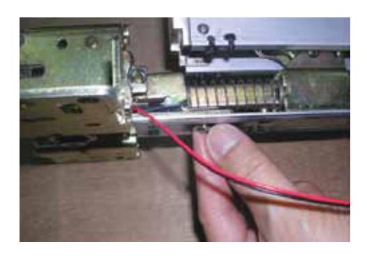
Insert the two wire connector of latchbolt monitor switch.
Note: After completion of latchbolt monitor switch, return to Step 6 on page 2 for futher installation instructions.

INSTALLING TAMPER SWITCH
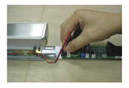
STEP ONE
Insert the 2-wire connector of end cap tamper monitor switch.
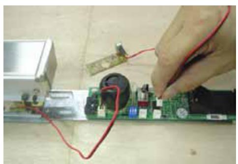
Note: After completion of tamper switch, return to Step 10 on page 3 for further installation instructions.
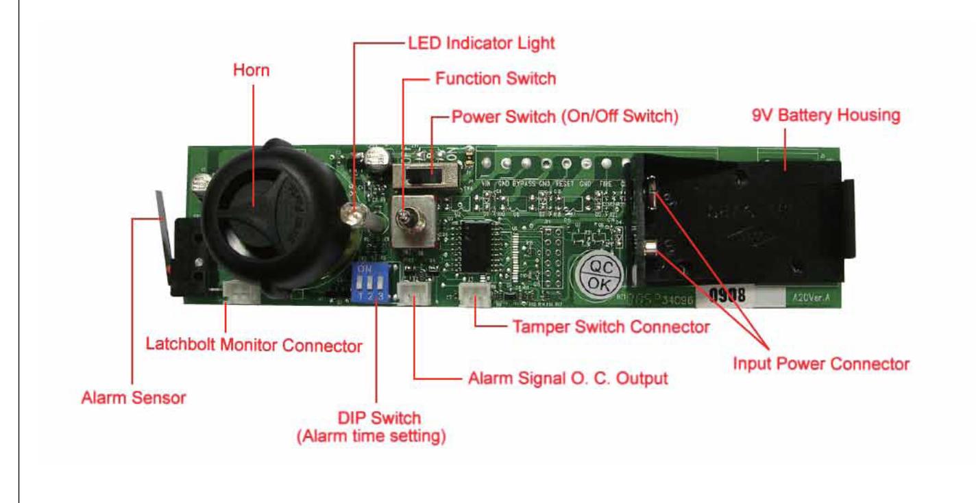
LED INDICATOR INFORMATION
- 1. Red Alarm mode (alarm will sound when push bar is depressed)
- 2. Green Alarm is disarmed
- 3. Blue Service mode (no alarm will be actuated when push bar is depressed)
- 4. Alternating red and green flashes Low battery signal in alarm mode (change battery as soon as possible)
OPERATIONAL INFORMATION
- 1. Turn key clockwise for one click, the LED will turn red to indicate "Alarm On."
- 2. Turn key counterclockwise one click to deactivate alarm when alarm is sounded, the LED will turn green for two seconds, then it will resume red light. Green light indicates "Alarm Off."
- 3. Turn key counterclockwise two clicks, the LED will turn blue that indicates "Service" mode for maintenance.
- 4. In case of low battery, turn off the power switch before replacing battery.
PRODUCT SPECIFICATIONS
Power: 9V 6LR61 (9V lithium battery)
Power Consumption: 150mA (max) Operating Temperature: -10C to 55C
Relative Humidity: 20% to 95% (non-condensing) Dimension: 168 mm (l) x 41 mm (w) x 36 mm (h)
Weight: 57 g (battery not included) Volume: 103 dB (at 10 cm distance away)
Output Port: Alarm signal O.C. Output (remote control provided)
REV 2 27390050 Page 8 of 8