Alarm Controls Exit Device Model SREX-100 Installation Instructions
Open the original PDF document
View PDFYOUR SOURCE FOR QUALITY SECURITY EQUIPMENT
MAGNETIC LOCKS
REQUEST TO EXIT STATIONS
DIGITAL KEYPADS
PUSHBUTTON CONTROL STATIONS
PNEUMATIC TIME DELAY STATIONS
VANDAL RESISTANT PUSH PLATES
MORTISE CYLINDER STATIONS
EXPLOSION-PROOF STATIONS
VANDAL RESISTANT STATIONS
EIGHT ZONE ANNUNCIATORS
CUSTOM GRAPHIC ANNUNCIATORS
PUSH BARS
RELAYS

ASSA ABLOY, the global leader
ACTIVE INFRARED REQUEST TO EXIT SENSOR
MODEL SREX-100 OPERATING INSTRUCTIONS

in door opening solutions
PN:111 713
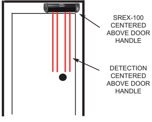
The SREX-100 is an active infrared request to exit sensor for interior applications located within the protected premise. It is U.L. listed as a request to exit device under the U.L. UL294 and the CAN/ULC-S319 standard. The SREX-100 is rated a "class 1" as per the CAN/ ULC-S319 standard. The SREX-100 is designed to mount over the door header so that its detection pattern is placed directly over the door handle. When the user reaches for the door handle the exit device releases allowing the person to exit. The active detection curtain is well defined to keep the door secure while rejecting parallel traffic and objects placed under it.
SPECIFICATION
- OPERATING VOLTAGE: 12 OR 24 VOLTS AC/DC, AUTO VOLTAGE SELECTION
- CURRENT DRAW: 155 MA., (SOUNDER OFF), 200 MA., (SOUNDER MAXIMUM VOLUME)
- RELAY CONTACT RATING: 1.3 A. @ 30 VOLTS DC OR 24 VOLTS AC
- RELAY CONTACT ARRANGEMENT: DOUBLE POLE-DOUBLE THROW, (2 FORM C)
- TEMPERATURE: FOR U.L. LISTED INSTALLATIONS +32 F TO +120 F, (0 C TO +49C)
- HUMIDITY: 0% TO 93% NON-CONDENSING FOR ULC-S319 INSTALLATIONS, 0% TO 85% NON-CONDENSING FOR UL-294 LISTED INSTALLATIONS.
- REQUEST TO EXIT INPUT: NORMALLY-OPEN DRY CONTACTS
- KEYPAD OR CARD READER INPUT: NORMALLY-CLOSED DRY CONTACTS
- DOOR POSITION SWITCH INPUT: NORMALLY-OPEN DRY CONTACTS
- SIZE: 6.875" L (174.63mm) x 1.875" H (47.63mm) x 2" W (51mm)
- MATERIAL: BLACK ANODIZED ALUMINUM AND ABS PLASTIC
- WIRING INTERFACE: 14 PIN CONNECTOR WITH 4 FEET OF CABLE
- CERTIFICATIONS: UL/CUL 294/S319, FCC PART B
- THE SREX-100 HAS A THREE YEAR WARRANTY
NOTE:
FOR U.L. LISTED INSTALLATIONS THE SREX-100 SHOULD ONLY BE POWERED BY A U.L. 294 LISTED POWER SUPPLY, AS WELL AS CONNECTED TO A U.L. LISTED ELECTRICAL LOCKING (EL) DEVICE. FOR CAN/ULC-S319 LISTED INSTALLATIONS THE SREX-100 SHOULD ONLY BE POWERED BY A ULC--S319 LISTED POWER SUPPLY AS WELL AS CONNECTED TO A ULC-S319 LISTED ELECTRICAL LOCKING (EL) DEVICE, CARD READER/KEYPAD AND DOOR/REX SWITCHES.
THE USE OF ANY ADD-ON, EXPANSION, MEMORY OR OTHER MODULE MANUFACTURED OR SUPPLIED BY THE MANUFACTURER'S REPRESENTATIVE WILL INVALIDATE THE CAN/ULC-S319 CERTIFICATION.
WHEN USED WITH ELECTRIC STRIKES ON SUPERVISED PORTALS, REQUEST-TO-EXIT DE-VICES SHALL BY-PASS PORTAL ALERTS CAUSED BY EXITING. WHEN USED WITH ELECTRO-MAGNETIC LOCKS ON SUPERVISED PORTALS, REQUEST-TO-EXIT DEVICES SHALL SIGNAL THE ACCESS CONTROL UNIT TO RELEASE THE ELECTROMAGNETIC LOCKS AS WELL AS TO BYPASS PORTAL ALERTS CAUSED BY EXITING.
TERMINAL AND LEADS COMPLY WITH CSA, C22.1, CANADIAN ELECTRICAL CODE, PART I, SAFETY STANDARD FOR ELECTRICAL INSTALLATIONS.
FOR U.L. 294 AND NFPA 101 SECTIONS 7.2.6.2.1 WIRE THE LOCKING DEVICE FOR FAIL-SAFE OPERATION.
CAN/ULC-S319 LIMITS THE RATED OUTPUT OF THE AUDIBLE SIGNAL DEVICE, (STATED AS A SOUND PRESSURE LEVEL), (SPL), FROM 70 dBA TO A MAXIMUM OF 100 dBA AT 1 METER. UL-294 LIMITS THE RATED OUTPUT OF THE AUDIBLE SIGNAL TO A MINIMUM OF 85 dBA AT 10 FEET.
THIS DEVICE COMPLIES WITH PART 15 OF THE FCC RULES. OPERATION IS SUBJECT TO THE FOLLOWING TWO CONDITIONS: (1) THIS DEVICE MAY NOT CAUSE HARMFUL INTER-FERENCE, AND (2) THIS DEVICE MUST ACCEPT ANY INTERFERENCE RECEIVED THAT MAY CAUSE UNDESIRED OPERATION.
TECHNICAL ASSISTANCE
IF TECHNICAL ASSISTANCE IS REQUIRED CALL 1 800 645-5538
TYPICAL INSTALLATION WIRING
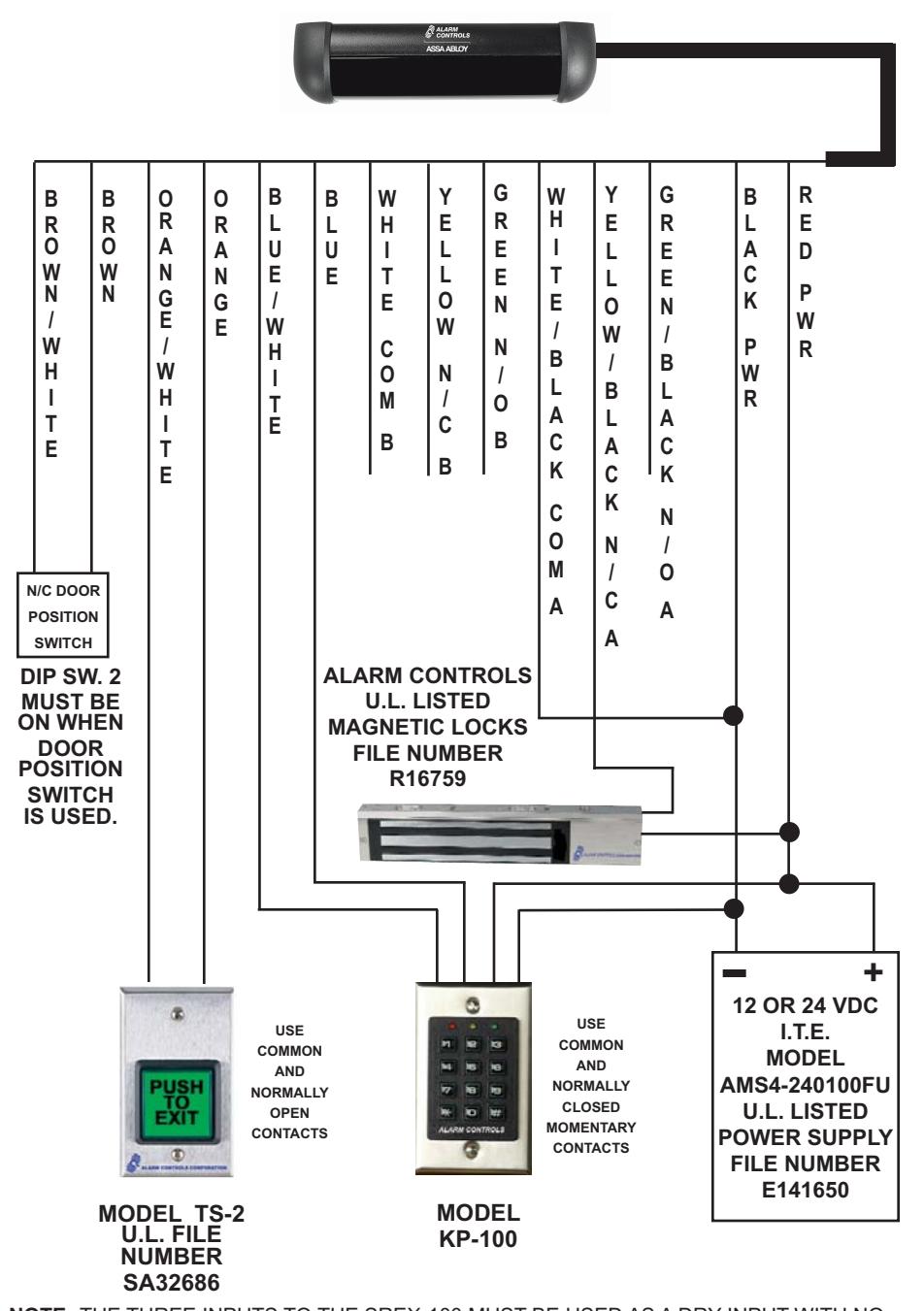
NOTE: THE THREE INPUTS TO THE SREX-100 MUST BE USED AS A DRY INPUT WITH NO VOLTAGE APPLIED FROM THE CARD READER, DOOR POSITION SWITCH OR THE REQUEST TO EXIT STATION.
SREX-100 INSTALLATION
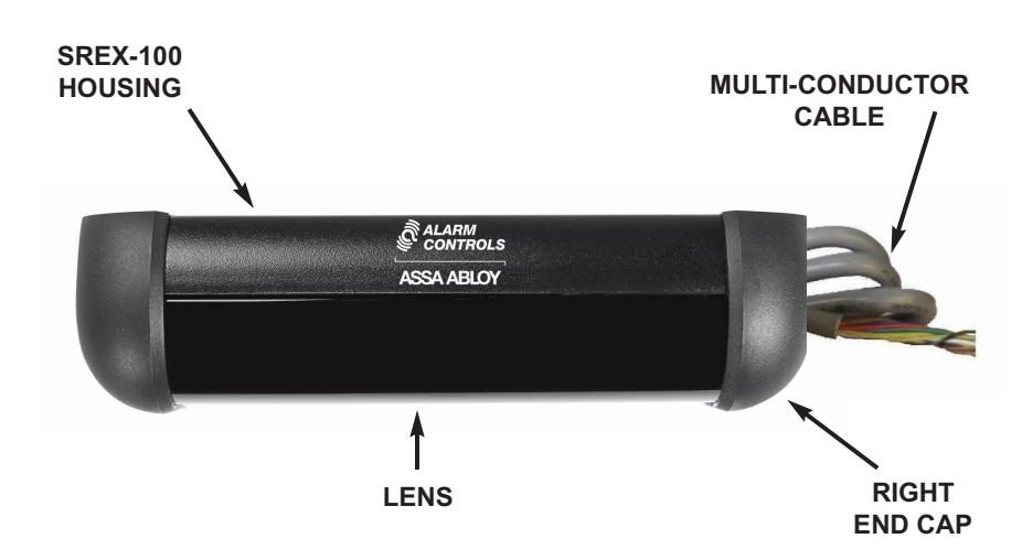
PREPARING THE SREX-100 FOR MOUNTING
- NOTE: The SREX-100 and devices connected to it must be mounted inside the protected area to be UL-294 and ULC-S319 compliant.
- STEP 1. Remove the Phillips head screw holding the right end cap. Take off the right end cap only.
- STEP 2. Slide the lens out of the housing.
- STEP 3. Slide the PCB with clips attached from the housing. Do not remove clips.
- STEP 4. Position the SREX-100 drill template on door frame or above door frame over door handle.
- STEP 5. A 5/16" diameter hole is required in door frame or mounting surface to allow cable entry. This hole is located at the right side of the housing thru the elongated hole.
- STEP 6. Fasten the SREX-100 housing with the two TEC screws provided. It may be necessary to drill a 1/8" pilot hole for ease of screw installation.
- CAUTION: ESD electrostatic discharge: The circuit board is vunerable to damage by electrostatic discharge. Before handling PCB dissipate your body's charge.
LED INDICATORS
GREEN Power ON and no detection.
RED Object in detection zone or input activated.
Hand in detection zone or request to exit input activated..
YELLOW Relay active.
FLASHING When sensor is or any of the enabled inputs are in constant
YELLOW detection for more than 10 seconds sensor will return to normal
when viewing field is clear.
BUZZER SOUNDS
When DIP SW 5 is in the ON position the buzzer will be enabled. BUZZER BEEPING Sensor is blocked for more than 10 seconds.
BUZZER ON STEADY DIP SW 2 is in timer mode, (Off). If the sensor is activated or
the REX input is closed or the card reader/keypad input is used. DIP SW 2 is in relock mode, (ON). Door position
COMPLETING THE INSTALLATION
- STEP 1. Make sure that the sensor releases the locking device.
- STEP 2. Test the detection height of the sensor.
- STEP 3. . Test the detection zone parallel to the door and in front of the door handle.
- STEP 4. Snap the PCB into the housing. The top of the PCB goes into the housing first.
TROUBLE SHOOTING THE INSTALLATION
If the SREX-100 is detecting erratically the sensor beams are reflecting off the handle. Adjust the angle of the sensor so the IR beams are in front of the handle.
TYPICAL DOOR INSTALLATION
PAGE 5 PAGE 2
CABLE COLOR CODE
|
C
A B L E W I R E C O L O R |
C
O F U N T I N |
|---|---|
|
R
E D |
1
2 O R 2 4 V A C / D C , A U T O S E N S I N G |
|
B
L A C K |
1
2 O R 2 4 V A C / D C , A U T O S E N S I N G |
|
W
H I T E / B L A C K S T R I P E |
C
O M M O N C O N T A C T R E L A Y A |
|
G
R E E N / B L A C K S T R I P E |
N
/ O C O N T A C T R E L A Y A |
|
O
/ C S Y E L L W B L A K T R I P E |
/
C C O C N N T A T R E L A Y A |
|
W
H I T E |
C
O M M O N C O N T A C T R E L A Y B |
|
G
R E E N |
N
/ O C O N T A C T R E L A Y B |
|
Y
E L L O W |
N
/ C C O N T A C T R E L A Y B |
|
B
L U E |
C
/ A R D R E A D E R K E Y P A D I N P U T |
|
B
L U E / W H I T E S T R I P E |
C
A R D R E A D E R / K E Y P A D I N P U T |
|
O
R A N G E |
R
E Q U E S T T O E X I T N / O I N P U T |
|
O
R A N G E / W H I T E S T R I P E |
R
E Q U E S T T O E X I T N / O I N P U T |
|
O
B R W N |
/
C O O O S O S C N D R P I T I N W I T H |
|
B
R O W N / W H I T E S T R I P E |
N
/ C D O O R P O S I T I O N S W I T C H |
NOTE: The SREX-100 contains a double pole-double throw relay and the two sets of relay contacts are referred to as A and B.
The Card Reader/Keypad and the Door Position Switch are dry inputs.
ADJUSTMENT OF SENSOR FIELD
The SREX-100 is factory pre-set at the five degree angle. If there is an obstruction in the sensor field preventing a clear view of the door handle it will be necessary to change the viewing angle. Un-plug the connector and slide the PCB from the housing with the clips attached. Do not remove the clips from the PCB! Change the viewing angle to the zero degree angle. It is recommended that the sensor be powered and both hand and walk tested. If the sensor is detecting erratically, the IR beams may be reflecting off the door handle and the viewing angle should be adjusted outward. Slide the PCB back into the housing and leave the right end cap off until all final adjustments have been made.
ZERO DEGREES FIVE DEGREES TEN DEGREES
THIS SIDE
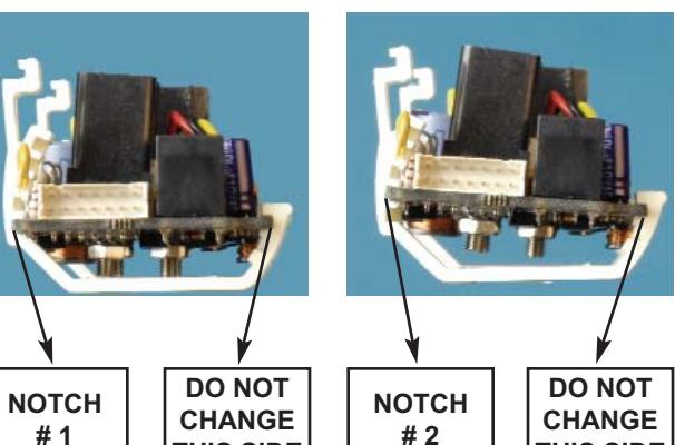
THIS SIDE
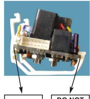
NOTCH # 3
DO NOT CHANGE THIS SIDE
ADJUSTMENT OF SENSOR
After the SREX-100 has been wired and powered the sensor can now be adjusted to the installation requirements.
DETECTION RANGE
The detection distance is adjusted by the RNG, (range), potentiometer located at the upper left hand side of the PCB. The range is 20 to 48 inches.
Turning the potentiometer clockwise increases the range, turning the potentiometer counterclockwise decreases the range.
RELAY ON TIME
The relay on time is adjusted by the TIME potentiometer which is the center potentiometer located at the upper left hand side of the PCB. The relay on time range is 1/2 to 60 seconds. The Time potentiometer is non-linear with the first 10 seconds covered by the first half of the potentiometer and 11 to 60 seconds covered by the second half of the potentiometer. Turning the potentiometer clockwise increases the relay on time, turning the poteniometer counterclockwise decreases the relay on time.
BUZZER VOLUME
The buzzer volume is controlled by the VOL potentiometer located at the upper right hand side of the PCB. Turning the potentiometer clockwise increases the buzzer volume, turning the potentiometer counterclockwise decreases the buzzer volume.
DIP SWITCH SETTINGS
SWITCH 1 ON FAIL-SAFE MODE
SWITCH 1 OFF FAIL-SECURE MODE
When the SREX-100 is in constant dectection, more than 10 seconds, It will go into a fail-safe or fail-secure mode depending upon the switch setting.
SWITCH 2 ON RELOCK MODE, DOOR POSITION
When a normally-closed door contact is installed the door will relock after the door is opened and then closed.
SWITCH 2 OFF TIMER MODE
The door will relock after the preset relay on time.
SWITCH 3 ON DOOR POSITION RELOCK TIME IS A FIXED 10 SECONDS
SWITCH 3 OFF DOOR POSITION RELOCK TIME IS A FIXED 30 SECONDS
SWITCH 4 ON DOOR UNLOCK TIMER
If switch 2 is in the off position,(timer mode), then door will remain unlocked as long as there is activity in the detection range. If there is no activity then the timer will restart and relock the door after the preset time.
SWITCH 5 ON BUZZER ENABLED, THE BUZZER IS NOT INTENDED TO BE A
BURGLARY ALARM
SWITCH 5 OFF BUZZER DISABLED
SWITCH 6 ON CARD READER OR KEYPAD INPUT IS ENABLED
SWITCH 6 OFF CARD READER OR KEYPAD INPUT IS DISABLED
SWITCH 7 ON BUZZER SOUNDS WHEN N/C CARD READER INPUT IS OPEN
SWITCH 7 OFF BUZZER DOES NOT SOUND WHEN N/C CARD READER INPUT IS
CLOSED