Alarm Controls Electric Strike Model AES-100 Installation Instructions
Open the original PDF document
View PDFAES-100
Electric Strike Installation Instructions and Technical Support UL 1034 · Grade 1

Alarm Controls 19 Brandywine Drive Deer Park, NY 11729 800.645.5538 www.alarmcontrols.com
ASSA ABLOY, the global leader in door opening solutions
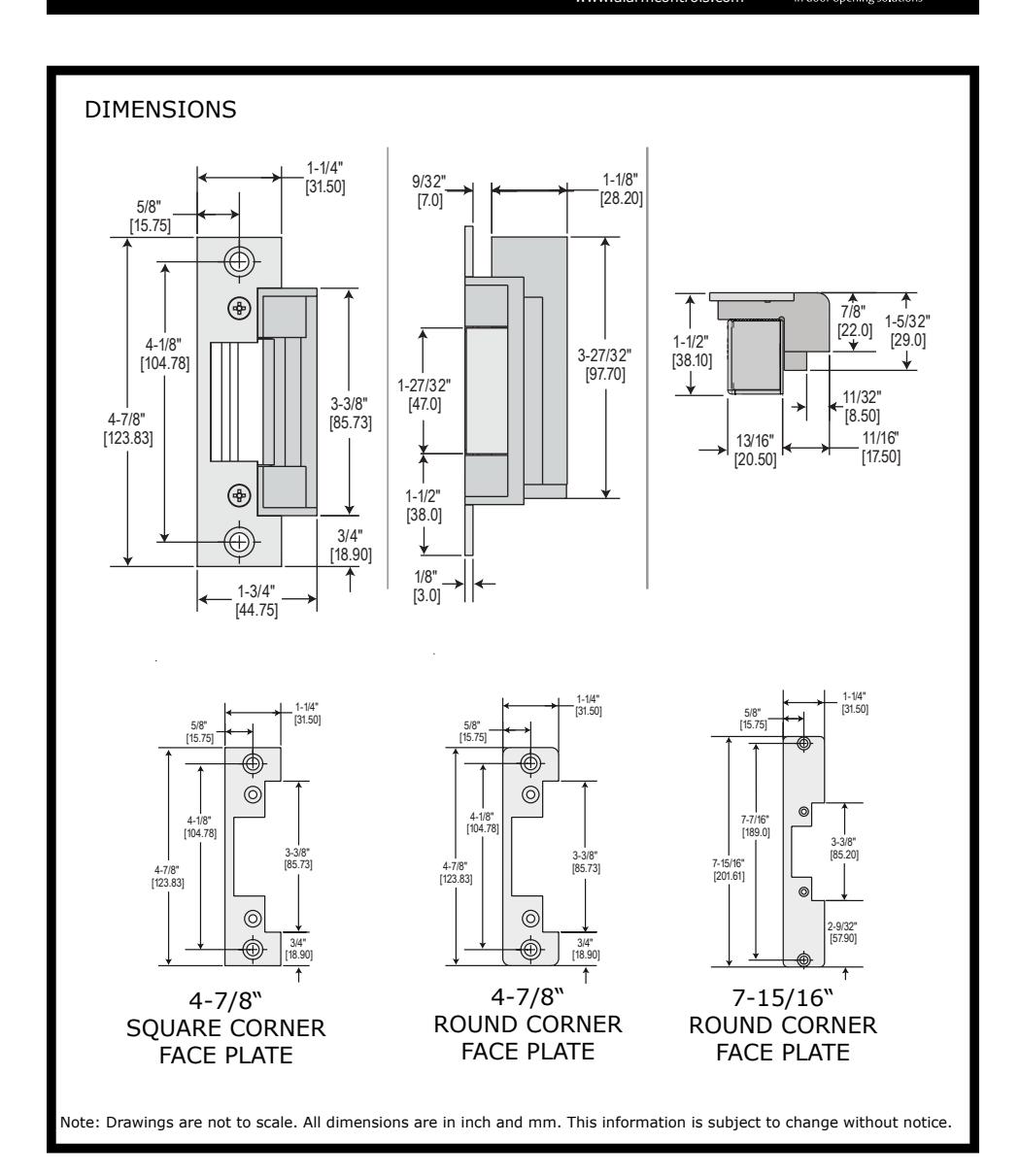
INSTALLATION INSTRUCTIONS
- 1. Prepare door jamb per appropriate template detail.
- 2. Install mounting tabs using #10-32 screws. Do not tighten. Set tabs for 1/8" thick face plate.
- Connect wires coming from the low voltage power source (see wiring diagrams and electrical specifications on page 3).
- NOTE: It is important to allow enough space behind the electric strike in the jamb cut-out for the wires. Bunching the wires inside the electric strike body may cause the unit to not operate properly.
- Install electric strike and option face plate to jamb using #12–24 machine screws or wood screws provided in the option package.
- Secure #10-32 screws holding mounting tabs (when applicable).
FIG. 1: DOOR JAMB DESCRIPTION
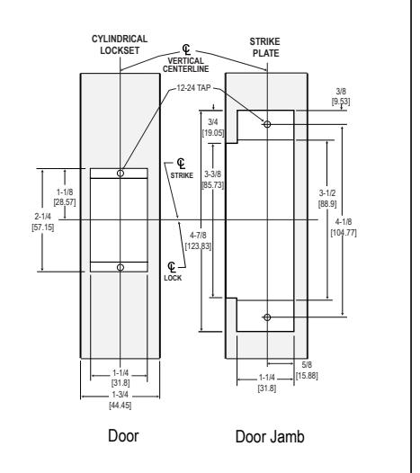
FIG. 2: JAMB INSTALLATION
Cutout dimensions for 4-7/8" Faceplate. Note: 1020 has radius corners.
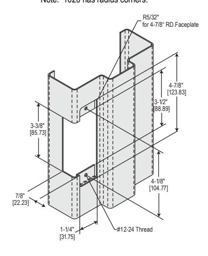
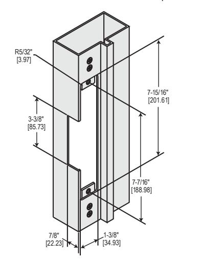
FIG. 3: JAMB INSTALLATION
Cutout dimensions for 7-15/16" Faceplate.
RETROFIT JAMB PREPARATION
TO FIND VERTICAL CENTERLINE
When Jamb:
- is not squared
- is warped
-
has heavy weather stripping
- conditions are not ideal
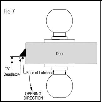
- 1. To determine the location of the Vertical Centerline of the mounting screw holes, first measure the distance from the outside face of the door to the face of the latchbolt (distance "A") (see FIG. 7).
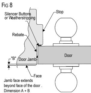
- 2. Close the door and measure the distance from the outside face of the door jamb (distance "B") (see FIG. 8). Do not force the door against the stop, close gently .
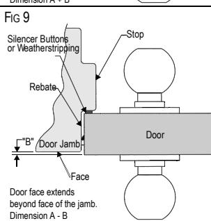
- 3. If the jamb face extends beyond the face of the door, add A and B (see FIG. 8). If the door extends beyond the jamb face, subtract B from A (see FIG. 9).
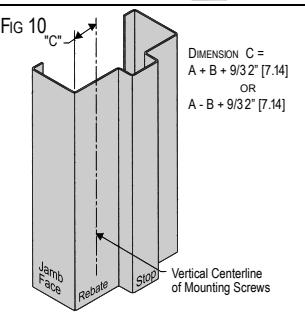
- 4. Using the dimension obtained add 9/32" [7.14 mm] (see FIG. 10). The resulting dimension "C" is the distance from the jamb face along the rebate to the mounting hole centerline of the Alarm Controls AES-100 Series Electric Strike.
Vertical Centerline:
Dimension A ± Dimension B + 9 /32" [7.14 mm] = Dimension C
TO FIND HORIZONTAL CENTERLINE
1. Mark the location of the lock centerline on the jamb face, as shown in figure 1 on page 1 .
ELECTRIC STRIKE TROUBLE-SHOOTING GUIDE
If the electric strike does not operate properly after installation, the following problems may need to be corrected. Please read carefully before calling for technical service.
Step 1. If the electric strike does not operate properly, open the door and re-energize the electric strike. If the electric strike operates properly with the door held open, the lockset may be pre-loading or binding the keeper of the electric strike.
Solution: The horizontal relationship between the lockset and the electric strike will have to be adjusted to eliminate the binding between the bolt of the lock and the electric strike keeper (also see note 2.)
Step 2. If the electric strike does not oper ate with the door open, remove the electric strike from the jamb leaving the wiring connected and re-energize the electric strike. If the electric strike operates properly outside of the jamb, then the problem may be from a tight-fitting jamb cutout pinching the sides of the electric strike together.
Solution: The electric strike cutout in the door jamb needs to be slightly enlarged.
Step 3. If all mechanical problems have been eliminated without successful electric strike operation check the following electrical problems:
- a. Examine the power supply or transformer to verify that the output voltage is at the listed rating
- b. Verify that the power wires leading to the electric strike are a large enough gauge to handle the current requirements. Note: Some voltage may be lost when using smaller gauge wires over long distances.
- c. Using a multimeter: Verify that the input voltage is within the recommended limits (+/- 10%)
- d. Confirm that the input voltage at the installation site is DC or properly rectified AC.
- e. Verify that all peripheral devices such as bridge rectifiers, SMART-Pacs, buzzers, LEDs etc. are properly connected.
- f. Check that the switch, key pad, etc., meets the voltage requirements for the system.
Note 1: A quick way to determine if an electric strike is defective is to install it in a site where another electric strike has been installed and working properly . Another way is to use an alternative power source to test the electric strike (i.e. a DC battery pack.)
Note 2: If the voltage is slightly too low to operate the electric strike, a 35 volt, 220 micro farad capacitor may be installed across the bridge rectifier (positive to positive, negative to negative) to provide an initial boost of power to the unit. This is also helpful to overcome slight pre-loading conditions (as in step 1.)
WIRING DIAGRAMS AND GENERAL SPECIFICATIONS
CAUTION! Before connecting any device at the installation site, verify input voltage and current using a multimeter. Many power supplies and transformers operate at higher levels than listed. Any input voltage exeeding 10% of solenoid rating may cause severe damage to the unit and will void the warranty.
GENERAL INFORMATION
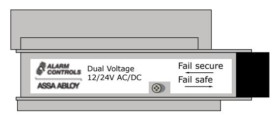
This electric strike is equipped with a field selectable 12 V DC/AC and 24 V DC/AC dual voltage solenoid. 12V is preselected.
WIRING AND VOLTAGE SELECTION
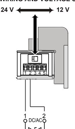
12 V/0.2 A 24 V/0.1 A
Strike solenoid
|
MINIMUM WIRE GAUGE
REQUIREMENTS |
Solenoid Voltage | |
|---|---|---|
| 24 VDC | 12 VDC | |
| 200 feet or less | 18 gauge | 14 gauge |
| 200 - 300 feet | 18 gauge | 12 gauge |
| 300 - 400 feet | 16 gauge | 12 gauge |
Alarm Controls electric strikes are not polarity sensitive.
FAIL SAFE/FAIL SECURE SELECTION
SPECIFICATIONS
AES-100 (fail secure)
|
ELECTRICAL RATINGS
FOR SOLENOID |
Continuous Duty | Operating Temperature | -10°C to +40°C, 14°F to +104°F | |||
|---|---|---|---|---|---|---|
| 12 VDC | 24 VDC | 12 VAC | 24 VAC | MECHANICAL RATINGS | ||
| Resistance in Ohms | 58 | 230 | 58 | 230 | Static Strength | 1500 lbs - force |
| Watts Seated | 2.5 | 2.64 | 1.56 | 1.68 | Dynamic Strength | 70 ft - lbs - force |
| Amps Seated | .21 | .11 | .13 | .07 | Endurance | 250 000 cycles |
Solenoids are rated at +/- 1 0% indic ated value
Limited Lifetime Limited Warranty