Alarm Controls APS-300 Series 1224 Power Supply Installation Instructions
Open the original PDF document
View PDFAPS-300 Series 12/24 Power Supply 9.8VDC-13.7VDC @ 2.8 Amps max / 20.0VDC-27.5VDC @ 1.4 Amps max Power-limited
Features APS-300 Series:
- Small Self Contained Efficient
- Universal AC Input 110-240VAC
- Operates under Brown Out conditions
- 9.8VDC-13.7VDC, 2.8A/20.0VDC-27.5VDC, 1.4A Selectable Continuous Duty
- Input and Output Surge Protection
- Power Limited Output with Thermal Protection
- AC and DC LED's
- Quality Manufactured in the USA with a lifetime Warranty
- Outputs are Power Limited
- Provided in Standard Enclosure 14"x 8.5"x 3.5"
- Precise Battery Regulation for all sealed Lead Acid Battery(s)
- Battery Online, No Drop or Switch Over with AC Power Fail
- Reverse Battery Protection
- Comes with plug in battery cable assembly
- UL and cUL tested to Standards UL 603 Burglar Alarm Power Supplies, UL 294 Access Control Units, and ULC-S318-96 Canadian Standard for Power Supplies for Burglar Alarm Systems
- Relay "C" Contacts Indicates AC Power Status
- LTW Limited Warning of stand by battery(s)
- Battery Disconnect on depleted Battery(s)
Ordering examples:
| APS-300 |
Supervised Power Supply/Charger module with
Standard Enclosure 14" x 8.5" x 3.5" |
|---|---|
| APS-3004C |
APS-300 with one PD-4C, four output PTC
protected distribution board |
| APS-300FT | APS-300 with one PDFT fire relay module |

Alarm Controls Corporation 19 Brandywine Drive Deer Park, NY 11729
500-33315_A Installation specifications subject to change without notice
Phone: (800) 645-5538 info@alarmcontrols.com www.alarmcontrols.com
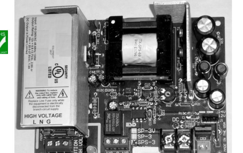
Description
The APS-300 Series Power Supplies are heavy duty self contained, efficient clean off-line switching power supplies that are selectable between 9.8VDC-13.7VDC at 2.8 Amps, and 20.0VDC-27.5VDC at 1.4 Amps. With the universal AC input, these supplies may be connected anywhere in the world with no plug-in transformer or any alterations. These power supplies have exceptional brown out capability with operation down to 60VAC. The extensive filtering system provides a very clean DC output that can power the most sensitive electronic controls and reader where a linear power supply is recommended. All of the supplies are power limited and thermally protected. All output faults are self restoring.
The APS-300 series have a precision lead acid battery(s) charger that obtains maximum battery life while providing a 9.8VDC-13.7VDC or 20.0VDC-27.5VDC uninterruptible power supply. The APS-300 Series are protected against Battery(s) reversal, shorting or overloading. Before connecting AC and battery(s), set 12V/24V selector jumpers to the desired voltage.
Caution , damage will occur if jumpers are moved with DC output load or Battery connected. Confirm proper voltage before connecting devices.
The APS-300 has the additional supervisory features of a set of form "C" relay contacts that indicates AC power status and a special electronic circuit that limits the output current to provide power limiting and load disconnect when battery is depleted.
Specifications
AC Input: L, N, G - 3P Orange Terminal block
Safety block with recessed hardware insulation that will accept up to 12AWG
L= Line, N= Neutral, and G = Ground
AC Input Rating ....................... 110-240VAC/47-63Hz 130W
Note: The Ground connection on the APS-300 is connected to the enclosure with a metal standoff.
AC LED Indicator (Next to AC Input Terminal)
The AC indicator is a green LED, which is illuminated when AC is present.
AC Line Primary Fuse
Fuse: GMA-2 5mm x 20mm 2A 250VAC
Replace this fuse only while the equipment is electrically disconnected from the branch-circuit supply. The proper size 2A fuse must be used.
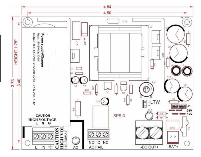
DC VOLTAGE SELECTOR JUMPER J1
The selector jumper J1 selects the voltage to 12 or 24VDC. As marked on the PCB, jumping 1&2 and 3&4 sets the supply to 12V range. Jumping 2&3 sets the supply to the 24V range.
CAUTION To prevent damage, remove DC load and battery(s) connections before switching selector J1 jumpers.
DC OUTPUT: 2P Terminal block
| Output voltage Range: 12V/24V | |
|---|---|
| 9.8VDC-13.7VDC/20.0VDC-27.5VDC | |
| Output voltage typical AC ON 13.65/27.30VDC | |
| Output continuous current 12V/24V 2.8A/1.4A |
| Current Overload Short Circuit Protection Yes | |
|---|---|
| Thermal runaway Protection Yes |
Current Overload and Thermal shutdown will auto-restart without removing load.
| Power limiting Yes |
|---|
|
Ambient operating temp. range32o
F(0o ) to 120oF (49o C) |
|
Storage Temperature60o
F to 190o F |
| Switching Frequency 132KHz |
| DC LED Indicator (Adjacent to DC Output) Red |
| Battery Connector: (Header plug marked [–Bat+]) |
|
The battery charger is set to charge 12V or 24V sealed or wet
lead acid batteries. Two 12V batteries are connected in |
lead acid batteries. Two 12V batteries are connected in series for 24V with a provided wire assembly p/n: WA-24SW. A 15" Battery cable assembly p/n: WA-15IBAT is provided that plugs from module battery connector to the battery. Red (+) 12VDC, Black (–) Neg.
Each of the 3 wires listed above that connect to the standby Batteries are covered with special clear tubing that provides additional insulation to ensure proper separation or Power Limited and NON Power Limited wires.
Supports any type of lead acid Battery(s)
| 12v 4AH-18Ah | |
|---|---|
|
UL evaluated with 18Ah on 12V and (2) 9Ah on 24V sealed
lead acid battery(s) |
| Battery(s) PTC self resetting Circuit Breaker 3A PTC | |
|---|---|
| Battery(s) Reverse hookup protection Yes |
To estimate the recharge time in hours for depleted battery(s), multiply the AH rating times 4 (Ah x 4). As an example, a 24V system with two depleted 12v 7Ah batteries would take about 28 hours to re-charge.
APS-300 Series Installation continued
APS-300 Supervision features:
DC Output Electronic Power Limited .............................. Yes This feature limits the output current to a maximum peak of 6 Amps to comply with UL Power Limiting requirement.
AC Status Output Relay: 3P Terminal block
AC Fail form "C" contacts rating .......................... 2A, 24VDC
Three position AC fail terminal block marked "NO, C, NC" are shown in the Normal, energized, "AC ON" condition.
Using these relay contacts as a switch with a proper DC power source the AC power loss can be locally annunciated as required with Amber or Red Led indicator or sounding device. The contacts may also be used to annunciate, AC failure to a Listed Burglar Alarm or Access Control panel.
Trouble / LTW Limited Time Warning of stand by batteries 95% of Battery has been depleted .
Output, 2 position header .1" spacing ( +&- ) ...... ( -) sinks 3mA. The LTW circuit "MUST" be connected either for local or remote annunciation with an Amber or Red LED to indicate DC Trouble or you may annunciate the LTW by connecting the (-) negative open collector output to an appropriate input of a UL Listed Burglar Alarm or Access control panel. When DC Power is normal, the (-) negative output is an open circuit with the LED OFF. When the DC output voltage drops to a point where the standby battery has been 95% depleted, the LTW (-) turns the LED ON to indicate trouble. The LED remains ON after the Stand by battery has been electrically removed from the DC Output.
The Figure LTW Led below shows the hook up on an LED. The following parts (not provided) will be needed to connect the LED to the LTW Header Output.
1 Connector housing .1" spacing with ramp Molex
P/N: 22-01-2021
2 Female connecters for housing Molex
P/N: 08-50-0113
Wire to connect LED connectors are rated for 22-30AWG
Figure LTW LED

Low Battery Disconnect (Battery cut-off)
12v/24v ............................................ 9.8VDC/VDC/19.6VDC
APS-300 Physical Dimensions
For Indoor Use Only
Module Dimensions ....................... 4.84"L x 3.73"W x 2.25"H Height includes required 5/8" #6 FF Hex aluminum standoffs, not provided with module only.
Mounting Holes Center to Center ................ 4.50"W x 3.41"H APS-300 Dimensions…… ........................... 14"W x 9"H x 3.5" APS-300 Weight ........................................................... 6.7Lbs
Standards
RoHS Compliant Lead Free – Not evaluated by UL
UL 603 Power Supplies for Use with Burglar Alarm Systems.
UL 294 Access Control System Units.
ULC-S318-96 Power Supplies for Use with Burglar Alarm Systems.
APS-300 Series Power Supply/Charger Installation Guide
The APS-300 with standby battery(s) provides an uninterruptible 9.8VDC-13.7VDC or 20.0VDC-27.5VDC power source. When use with optional Power Distribution modules PD4C or PDFT, it can provide multiple fused outputs or Fire Interface. The DC output on the APS-300 power supply is Power Limited. This makes all subsequent outputs power limited.
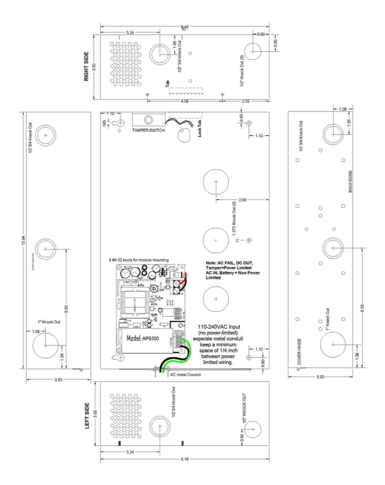
- 1. The installation of this power supply shall comply with the National Electrical Code (ANSI/NPFA 70), the Canadian Electrical Code, Part 1, and be in accordance with any additional requirements imposed by the local authority having jurisdiction.
- 2. For use in Indoor Location Only, Mount the Power Supply in desired location. Using the two keyholes on the upper end and the two or three holes along the bottom, mount the enclosure to the wall with appropriate fasteners.
- 3. Select output voltage by shifting the jumper J1 for 12VDC or 24VDC. Only change output voltage when AC is OFF and Batteries are not connected . The APS-300 Series has a continuous output rating of 9.8VDC-13.7VDC at 2.8 Amps or 20.0VDC-27.5VDC at 1.4 Amps. If a power distribution product is used, the total current draw of these devices must be subtracted from the available current rating. See selection table below or individual data sheets. Connect AC Line voltage, 110-240VAC with Earth Ground to the Orange AC input Terminal block. This wiring must be run in separate metal enclosed wiring system only. Note, Ensure all wiring is of appropriate gauge for device being powered. All Power Limited circuits must be separated by a minimum of .25" from Non-power Limited circuits.
- 4. Connect DC devices to the Output Terminals. Observe polarity. On the distribution boards Negative is identified with a (-) or (COM). The Positive is identified with (+) or (HOT). Exit the DC wiring out any of the other available knock outs keeping all the low voltage wiring away from the high voltage wiring and battery leads.
- 5. If supervision is desired, connect N/C Tamper switch and AC fail form "C" contacts to Security system for annunciation.
- 6. Add the current draw of the distribution boards to your load calculation to ensure your power requirements are within the unit's continuous power rating. Always check the spec sheet; but as a rule, each LED draws 6mA and each relay draws 20mA.
- 7. Confirm with Amp meter that your total continuous current conforms to the output current rating and that each output rating is proper for the powered device(s).
- 8. Connect AC fail contacts to annunciate AC Status condition.
- 9. Connect appropriate standby battery(s). Remove AC and confirm battery output to test standby battery(s). Mark installation date on Battery with permanent marker.
- 10. Each protected output on the optional power distribution board PD4C has a Green Status LED. Green ON indicates ready.
- 11. To reset a tripped PTC Circuit Breaker, you may have to turn power off on outputs, or remove faulted circuit output for up to 2 minutes. This allows the PTC re-settable circuit breaker to cool and reset to its normal "ON" condition.
- 12. For installation and use of optional PD4C and PDFT, see separate enclosed instructions.
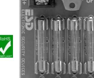
CAUTION: Replace fuses as marked
When calculated your total DC current be sure to add the current of any distributions options you are using. Be sure your normal continuous DC current draw does not exceed the marked rating of the supply. Select 12/24 J1 only with AC off and Batteries disconnected.
Battery Selection
The table below shows typical standby time in hours for various loads and batteries. The table works for either 12V or 24V batteries. The APS-300 has been evaluated by UL with an 18Ah sealed lead acid battery for 12V and (2) - 9AH batteries for 24V to meet the 4 hour stand by requirement.
Note: UL requires a minimum of 4 hours of standby time for Commercial Mercantile Burglar Alarm. The table below has the required battery size highlighted (*) to provide this 4-hr stand by time under a full rated load.
Approximate Battery Standby Time Table with a reserve of 3 Amps for 5 minutes for Alarm
AH = Amp Hours Capacity at a 20 hour rate - Hrs = Hours
|
Total Output
Amps |
4Ah Battery
Standby |
7Ah Battery
Standby |
9Ah Battery
Standby |
18Ah Battery
Standby |
24Ah
Standby |
|---|---|---|---|---|---|
| 1A | 2.92 Hrs | 5.32 Hrs | 7.79 Hrs | 15.89 Hrs | 23.65 Hrs |
| 1.4A* | 2.09 Hrs | 4.75 Hrs | 5.56 Hrs* | 12.61 Hrs | 16.89 Hrs |
| 2A | 1.46 Hrs | 1.3 Hrs | 3.46 Hrs | 7.94Hrs | 10.64 Hrs |
| 2.8A* | 1.04 Hrs | 1.9 Hrs | 2.47 Hrs | 5.04 Hrs* | 7.60 Hrs |
The Battery recharge time is 2.6 hours for each 1 Ah Amp Hour of battery capacity with either 12V or 24V batteries. The minimum battery capacity is 4Ah and the practical limit is 24Ah UL evaluated with an 18Ah battery on the 12V configuration and (2) 9Ah batteries on the 24V configuration. Please see the Figures for 12V configurations and 24V configurations below in this document. UL Listed systems require that if standby batteries are to be used they must have a 4 hour capacity under the full rated load.
Recommended Maintenance
The power supply and stand by battery(s) should be tested at least once a year as follows:
- 1. Check LED's for normal state. AC ON Green and DC ON Red.
- 2. Check output voltage with normal load. With AC ON for 12V setting, DC output voltage should read between 12.83VDC-13.69VDC and 27.1 - 27.4VDC on the 24V setting.
- 3. Check DC Output Amps to be sure it complies with output rating.
- 4. Disconnect AC input. AC LED should be off, and the DC LED's should remain normal.
- 5. Check DC Output to be above 11.5VDC for 12v setting and 23.0VDC for 24V setting. This checks standby batteries to be operational. Sealed lead acid batteries have a typical life of 3 to 5 years. Test battery by itself as outlined in your battery instructions to be sure the Amp hour capacity is within proper range.
- 6. Re Apply AC and verify AC LED ON.
PDFT Fire Transfer Relay with EOL Trigger
Features:
- Non Latching or Latching mode
- 12 or 24VDC Operation
- Reverse polarity protected
- Normally ON & Normally OFF Output
- Output LED's indicate condition
-
Outputs can be Triggered with:
- 1. N/O or N/C Switch with Supervised (EOL)
- 2. N/C Switch with (OVR) over ride
- 3. N/C Switch with AUX-IN auxiliary
- 4. Ground on any trigger input when (GRN) Jumper is enabled
- Form C Contacts Indicates Trigger Status
- 12 Amp Transfer Relay Contacts
- Lifetime Warranty Made in the USA
- UL Listed Sub Assembly for Access Control and Burglar Alarm Systems

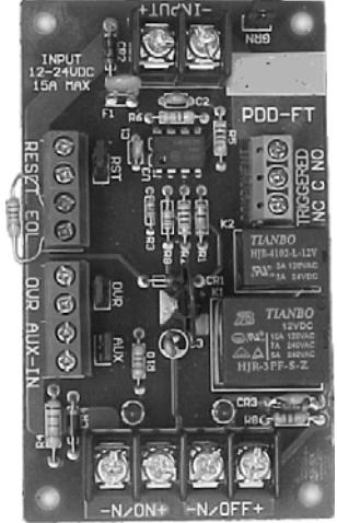
Description
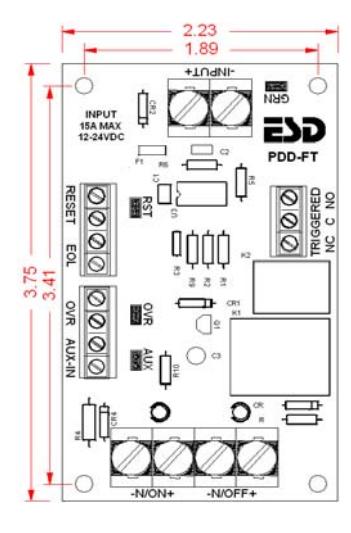
The PDFT transfers the input power from the normally ON output pair "-N/ON+" too the normally OFF output pair "- N/OFF+" when triggered. The unit is triggered when the supervised (EOL), end of line resistor is opened or shorted. The triggered form C user contacts indicate the state of the trigger. A typical application of the PDFT is to place a distribution board on one or both of the outputs, one of our power supplies on the Input, then connecting the EOL at a fire alarm panel to transfer the power from one distribution board to another when the Fire alarm panel is in the alarm condition. The transferred power would be used to unlock doors, shut down air systems, or return elevators to an exit floor.
Specifications / Instructions
Input Power "-INPUT+": 2 Pos. Terminal block with self clamping screws will accept multiple 12awg wires – Operates with 12 or 24vdc input. The input current is 70ma to control relays plus whatever output load is. The positive side of the power is connected to the swing arm of the transfer relay which directs the power to the proper output.
Output Power: 4 Pos. Terminal block Self clamping screws will accept multiple 12awg wires. "-N/ON+" are normally ON output power. This output is ON when the PDFT is not triggered. "-N/OFF+" is normally OFF. This output is ON when this unit is triggered. The transfer relay is rated at 15A@12v and 12A@24vdc.
Power LED's: A red LED above each output indicates which output is ON.
Input Trigger EOL: 2 Pos. Terminal block – Will accept 14- 28awg wire. This input must see the 2.2K ohm end of line resistor to be in the normal set condition. A change in resistance of + or – 60% will cause the trigger relays to drop out in the Triggered mode. This change in resistance is caused by the supervised wire between the EOL at the Fire panel and the PDFT being shorted or opened. The EOL supervises the pair of wires.
Input Trigger OVR: 2 Pos. Terminal block - Will accept 14- 28awg wire. This pair is normally closed, can be connected to an override switch. When OVR is open, unit will trigger.
Input Trigger AUX-IN: 2 Pos. Terminal block - Will accept 14-28awg wire. This pair is normally closed and can be connected to an auxiliary device. When AUX-IN is open, unit will trigger.
RESET 2 Pos. Terminal block – Will accept 14-28awg wire. When this pair is shorted, input triggers do not latch. If pair is open, the input triggers will latch until alarm is corrected and RESET is momentary closed to reset trigger.
Jumpers RST – OVR – AUX are jumpers with handles to short adjacent terminal blocks that are not used. You may move the jumper to one header to open short to enable adjacent terminals.
Jumper GRN – This jumper is used to enable ground supervision in the inputs. If the jumper is connected to both headers, and the mounting hole adjacent to jumper is connected to ground with a star washer, a ground on any of the input triggers will cause a trigger.
Trigger Status Terminal block - Will accept 14-28awg wire. Form C Contact with a 3 Amp rating will indicate the condition of trigger. C and NO are normally open in the normal energize not triggered state. C and NC are normally closed in the normal energized not triggered state. These contacts may be used to provide feedback to the FACP or other annunciating devices.
Module dimensions ....................... 2.23"W x 3.75"L x .8"H Mounting holes dimensions ........................ 1.89" x 3.41" Weight : ....................................................................... 2.2oz
UL Approvals for PDFT UL 294 – Access Control System Unit
UL 603 – Power supplies for Use with Burglar-Alarm Systems ULC S318-96 – Power supplies for Burglar Alarm Systems ULC S533-02 – Standard for Egress Door Securing and Releasing Devices.

Alarm Controls Corporation 19 Brandywine Drive Deer Park, NY 11729
500-33320_A Installation specifications subject to change without notice
Phone: (800) 645-5538 info@alarmcontrols.com www.alarmcontrols.com
PD4C Power Distribution Modules
PD4C
Multi Output
Low Voltage Power Distribution Modules
Life Time Warranty
Features/Specifications:
- Converts a single AC or DC (12 or 24v) Input to 4 PTC protected outputs
- Off/On switch disconnects load from output
- PTC circuit breaker ratings are holding current at 130oF per UL Standards
- Main Power Green/Red LED Indicates AC, DC or Reversed DC Input on PD4C
- Each output has a green status LED indictor
- Current Draw is 6ma max per LED
- Circuit Breaker Models with Rated Output 1.42 Amps or below are Power Limited
- All Input Terminal blocks and output terminal blocks on the PD4C module are rated 40A with a wire range of 10 – 18AWG
- Output Terminal blocks on the PDB4C are rated 10A with wire range 16-30AWG
- Size: PD4C 3 3/4"H x 2 1/4"W x 1"D Mounting: 3 7/16"H x 1.7/8"W
PD4C

UL 294 – Access Control System Unit UL 603 – Power Supplies for Use with Burglar-Alarm Systems ULC S318-96 – Power supplies for Burglar Alarm Systems ULC S533-02 – Standard for Egress Door Securing and Releasing Devices
| PD4C |
4 PTC Circuit Breaker Outputs with status LED's with
700mA fuses |
|---|

Alarm Controls Corporation 19 Brandywine Drive Deer Park, NY 11729
500-33325_A Installation specifications subject to change without notice
Phone: (800) 645-5538 info@alarmcontrols.com www.alarmcontrols.com