Aiphone WB-CA WB-CE Instructions
Open the original PDF document
View PDF

WB-CA, WB-CE
Stainless Steel Wall Mount Box with Assistance or Emergency Signage and a Light Cage
-INSTRUCTIONS-
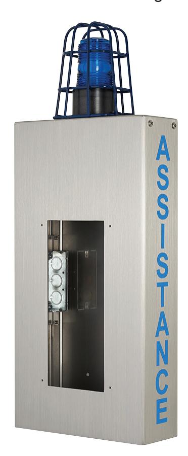
The WB-CA wall box comes with "ASSISTANCE" in reflective blue lettering on both sides of the box. A blue beacon/strobe light is mounted on top enclosed in a vandal resistant cage.
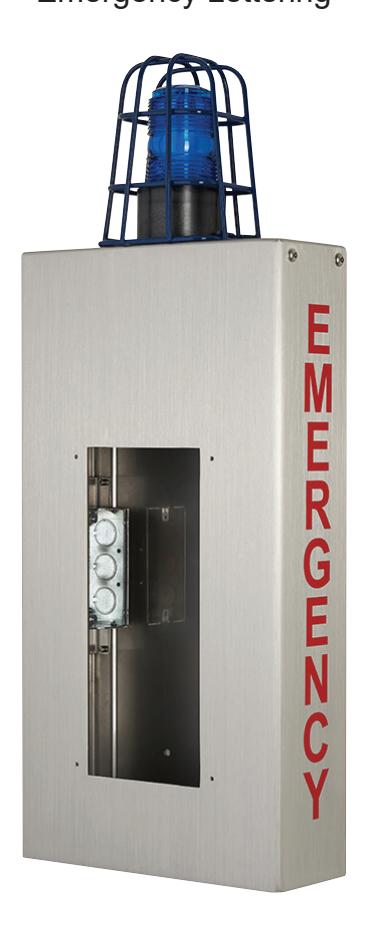
The WB-CE wall box comes with "EMERGENCY" in reflective red lettering on both sides of the box. A blue beacon/strobe light is mounted on top enclosed in a vandal resistant cage.
The WB-CA and WB-CE are made of 12-Gauge stainless steel and are weather/vandal resistant. The narrow 4" depth of the wall box allows it to meet all ADA mounting requirements. The blue beacon/strobe light requires a 24V DC power source, not included. Each box includes a UL Listed electrical box for installing an AC outlet, and a bracket to install a power supply internally. Compatible emergency /assistance sub stations include the IX-DVF-2RA*, IX-DVF-RA*, IX-SSA-2RA*, IX-SSA-RA*, IS-DVF-2RA*, IS-SS-2RA-R, and IS-SS-RA-R. * Stations available with French signage option. Please visit our website for more information (www.aiphone.com/home).
WB-CA Wall Box with Caged Light and Blue Assistance Lettering
WB-CE Wall Box with Cage Light and Red Emergency Lettering
MOUNTING/WIRING:
The WB-CA/WB-CE wall box comes pre-assembled with the beacon/strobe light and the cage attached. Mount the box to the wall, then wire the beacon/strobe light, power, and intercom sub station. Two screws are provided for mounting the power supply bracket to the internal bracket. Complete the installation by mounting the intercom sub station to the wall box. See below for additional information.
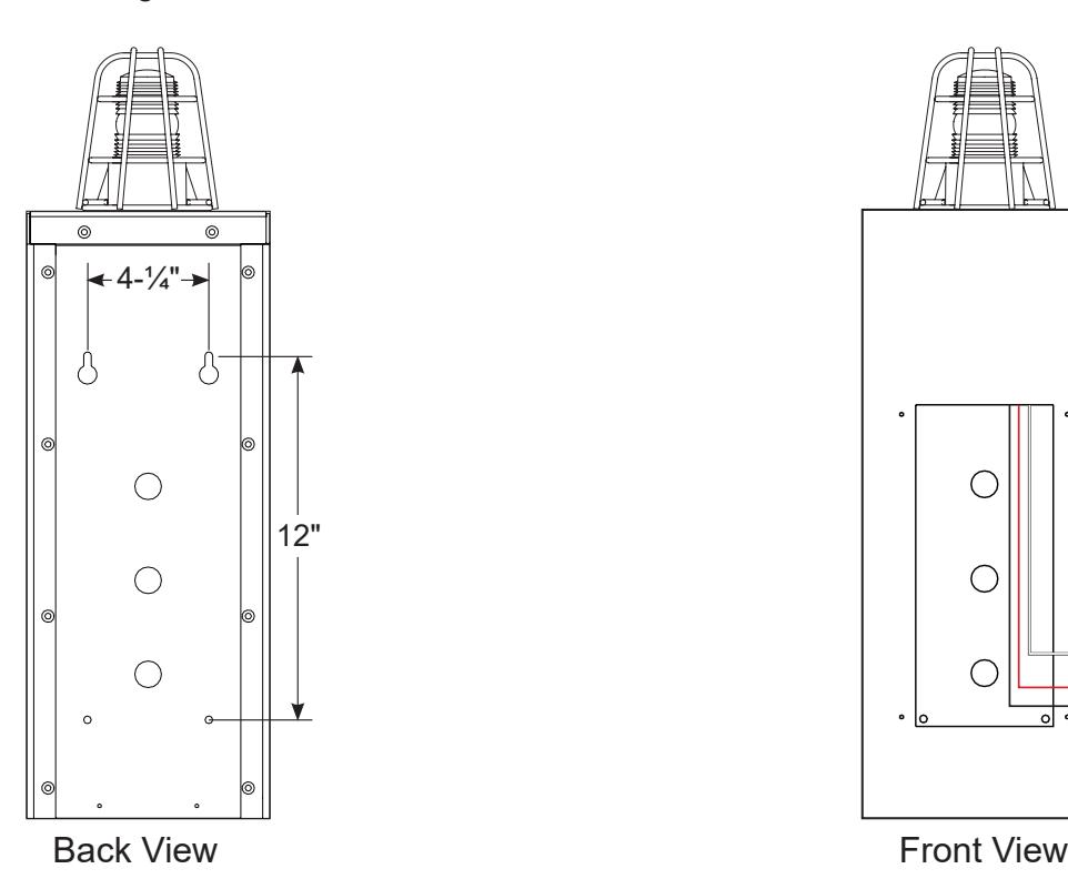
Secure the wall box to any flat surface using mounting hardware suitable for the surface you are mounting to. Top mounting holes are 4-¼" apart and top to bottom mounting holes are 12" apart. There are 3 knockouts on the back and 2 underneath for routing wire.
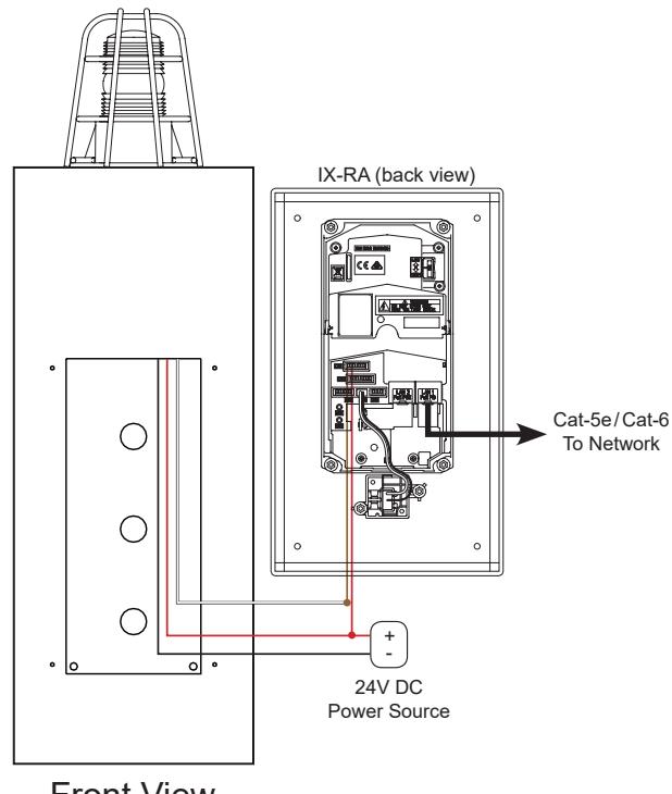
Connect the red and black wires from the beacon/strobe light to a 24V DC power source. Red to positive and black to negative. Connect the white trigger wire to the N/O side of relay 1 or 2 on the sub station. Connect the common of relay 1 or 2 to the positive of the 24V DC power source. See the sub station's installation manual for its complete wiring and dip switch setting options.
Relay 1 connection is shown in example above. Relay 1 must be enabled during the station programming process.
SPECIFICATIONS:
Surface box:
Mounting: Surface mount directly to wall Mounting Height: 48" AFF for camera to be at 60"
44" AFF for call button to be at 48"
Material: 12-Gauge Stainless Steel Color: Polished Stainless Steel
Dimensions:
Box only 20" H x 10- 9 ⁄16 " W x 3-⅞" D Including cage 26" H x 10- 9 ⁄16 " W x 3-⅞" D
Beacon/strobe light:
Voltage: 24V DC Current: 200mA
Wiring: Black: Ground
Red: +24V DC White: Trigger
Operating Temp: -40°F to 149°F