Aiphone RY-IP44 with ISIP Programming Manual Installation Instructions
Open the original PDF document
View PDF

RY-IP44
Input/Output Network Adaptor
Programming Manual For use with IS-IP Series
ATTENTION:
This manual is for programming the RY-IP44 wiht the IS IP Series only. Refer to the IS IP Network Direct Installation and Setting Manuals for complete installation/programming information.
For instructions featuring the RY-IP44 with the IX2 Series, visit www.aiphone.com/IX2-RYIP44 For instructions featuring the RY-IP44 with the IPW-1A, visit www.aiphone.com/IPW1A-RYIP44
Package Contents
- RY-IP44
- Programming Manual
- 6 Screw Terminal Blocks
- MAC Address Label
Installation Requirements
- General understanding IS-IP Series programming
- 9-30V DC power supply (sold separately)
- Unique IP address for each adaptor
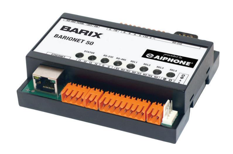
Overview / Description
The RY-IP44 is a Barix Barionet 50 with proprietary firmware installed for the device to function with the Aiphone IS-IP Series stations.
The 4 relay outputs can be programmed to trigger for door release, while calling, while communicating, or while calling and communicating.
The 4 contact inputs can be programmed to trigger a call with the IS-IP system. Examples of when this could be used are: an invalid card swipe, motion detector activation, or selective calling from multiple call buttons
The RY-IP44 is not a PoE device and requires a dedicated 9-30V DC power supply. Use the Aiphone PS-1208UL power supply (sold separately).
Creating the SIF.ini File
Important:
The intercom system should be fully programmed and operational prior to programming the RY-IP44 adaptor.
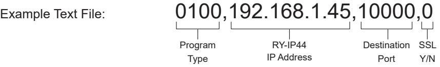
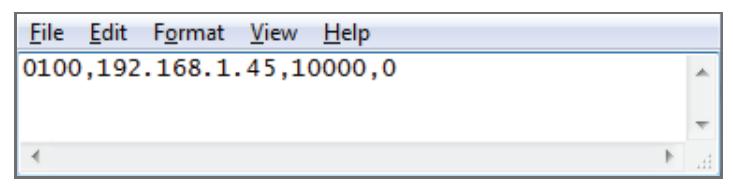
Creating a simple line of code, in the form of a .ini file, is required to allow an IS-IP station to communicate to the RY-IP44. The example below is shown using a common text editor (i.e. Notepad), and saving it with an .ini extension.
Program Type: A binary number between 0100 and 1111.
RY-IP44 IP Address: IP address assigned to the RY-IP44 (Must be unique for each RY-IP44).
Destination Port: Port number assigned on the RY-IP44. The default port is 10000. This can be
set in the range from 1 to 65535 (Must be unique for each RY-IP44).
SSL Y/N : This device does not use SSL. Input 0 for no.
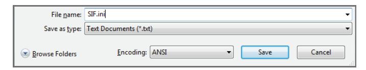
Save the SIF file with a .ini extension (.ini must be typed manually) to a location on the PC being used for programming the IX Series or IS-IP Series stations. This file must be uploaded to each device associated with the RY-IP44 using the instructions that follow.
Uploading SIF.ini File
Upload the SIF.ini file to each IS-IP Series station associated with the RY‑IP44 adaptor. ! Note that the IP address for each station will be unique for your network settings.
Important:
The intercom system should be fully programmed and operational prior to uploading the SIF.ini file.
- A. Open a web browser and type https://[ip address]/sif in the address bar. [ip address] = static IP address assigned to the station being programmed.
- B. A security certificate error message will appear. Select "Continue to the website."
- C. Enter the administrator ID and password.
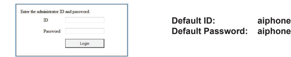
Default Password: aiphone
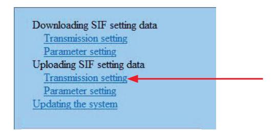
D. Select Transmission setting under Uploading SIF setting data from the menu on the left side of the screen.
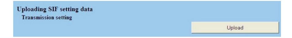
E. Click the Upload button. A new window will open.
- F. Click the Browse button and navigate to the .ini file saved on the PC.
- G. Click the Upload button. A message will appear stating the settings will not be applied until the system is updated.
- H. Click Updating the system from the menu on the left. Click the Update button and the unit will update and restart itself.
- I. Repeat this process for each door and master station associated with the RY-IP44 adaptor.
Configuring the RY-IP44 (assigning IP address and system use)
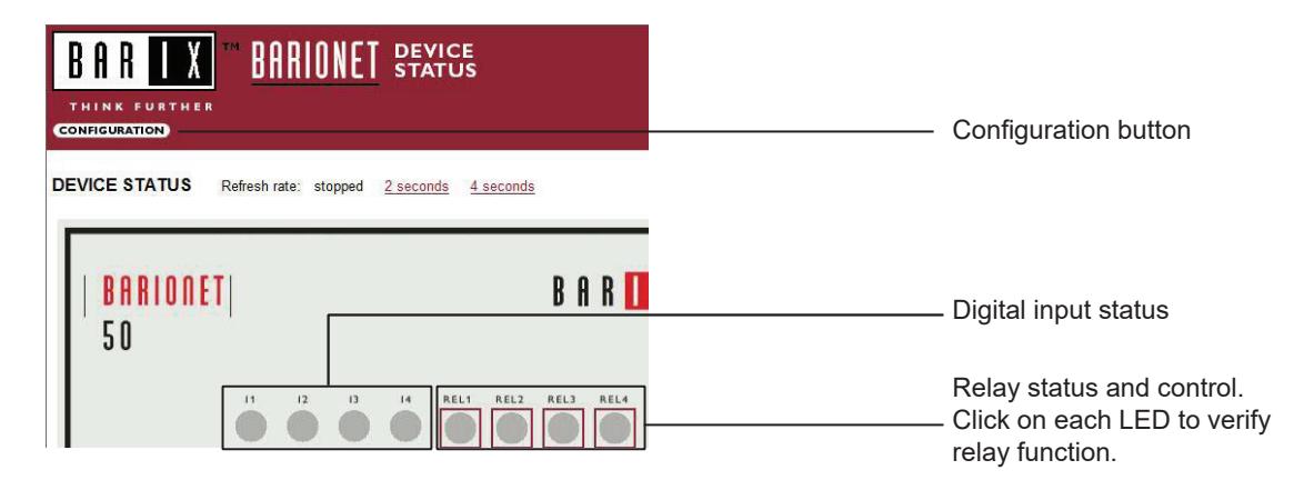
The RY-IP44 has a default IP address of 192.168.1.45. Open a web browser and point the address bar to 192.168.1.45 for access to the adaptor. The first screen to appear will be the Device Status screen.
Click the CONFIGURATION button to open the Device Configuration screen. This is where a unique IP Address , Netmask , and Gateway can be assigned to the adaptor. Consult with your IT department for these settings.
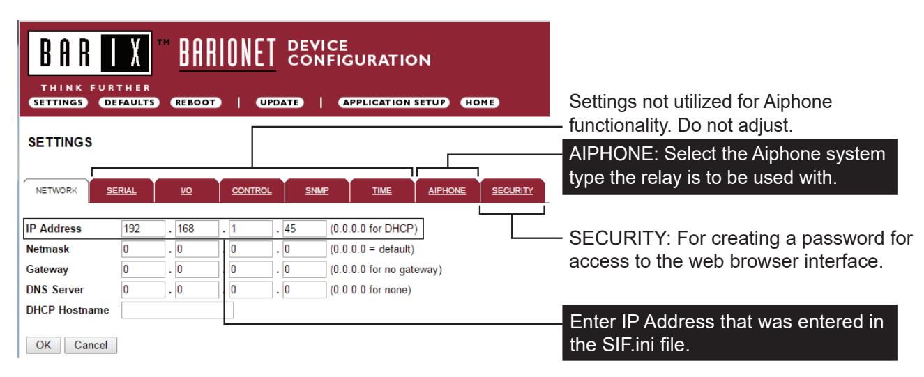
The Aiphone system type that the adaptor is being integrated with will need to be selected. Click the AIPHONE tab. Use the drop down by System Type to select the appropriate system. Enter the SIF Socket Local Port number that was assigned in the SIF.ini file (Destination Port). When done, click OK. Click Reboot on the next screen to restart the adaptor.
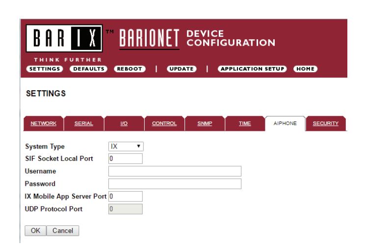
System Type : Select IS
SIF Socket Local Port : Enter the port number that was entered in the SIF.ini file. Leave at "0" to use default 10000 port.
Username & Password : Enter system's username and password. Leave blank if using default (aiphone).
Linked Stations Table
The RY‑IP44 has 4 relays that can be programmed to trigger when a specific door station is calling, while in communication, or while calling and communicating. The relays can also be programmed for door release from one or multiple IP master station(s).
Set the RY-IP44 for use with the IS-IP Series (refer to page 5).
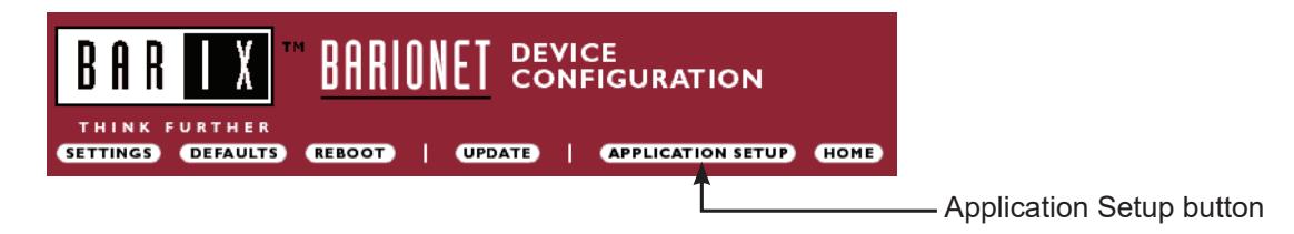
From the Device Configuration screen, click APPLICATION SETUP .
Linked Stations Table:
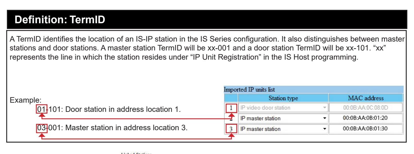
Enter the IP address and TermID for each IS-IP station in the IS configuration. This table is used as a reference for each station in the system that will be able to communicate with the RY-IP44 adaptor.
| N. IP ADDRESS | Term ID | N. IP ADDRESS | Term ID | ||||||||||
|---|---|---|---|---|---|---|---|---|---|---|---|---|---|
| 1 | 192 | . 168 | . 0 | . 41 | 05 | - 001 | 17 | 0 | . 0 | . 0 | .0 | 00 | - 000 |
| 2 | 0 | .0 | . 0 | . 0 | 00 | - 000 | 18 | 0 | . 0 | . 0 | . 0 | 00 | - 000 |
| 3 | 0 | . 0 | . 0 | . 0 | 00 | - 000 | 19 | 0 | . 0 | .0 | . 0 | 00 | - 000 |
| 4 | 0 | .0 | .0 | . 0 | 00 | - 000 | 20 | 0 | . 0 | . 0 | . 0 | 00 | - 000 |
| 5 | 0 | . 0 | . 0 | . 0 | 00 | - 000 | 21 | 0 | . 0 | .0 | .0 | 00 | - 000 |
| 6 | 0 | .0 | . 0 | . 0 | 00 | - 000 | 22 | 0 | .0 | . 0 | . 0 | 00 | - 000 |
| 7 | 0 | . 0 | . 0 | . 0 | 00 | - 000 | 23 | 0 | .0 | .0 | .0 | 00 | - 000 |
| 8 | 0 | . 0 | . 0 | . 0 | 00 | - 000 | 24 | 0 | . 0 | . 0 | . 0 | 00 | - 000 |
| 9 | 0 | . 0 | . 0 | . 0 | 00 | - 000 | 25 | 0 | . 0 | . 0 | .0 | 00 | - 000 |
| 10 | 0 | .0 | . 0 | . 0 | 00 | - 000 | 26 | 0 | . 0 | . 0 | . 0 | 00 | - 000 |
| 11 | 0 | . 0 | . 0 | . 0 | 00 | - 000 | 27 | 0 | . 0 | .0 | .0 | 00 | - 000 |
After inputting each IP address and TermID, click Apply Settings at the bottom of the page to save the settings to memory. Return to the Application Screen or reboot adaptor by clicking the Reboot button. Rebooting must occur to update adaptor settings.
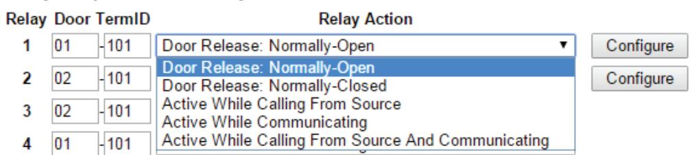
Relay Output Programming
Relay Functionality:
Enter the TermID for the door station to be associated to the relay. Select the relay action from the drop down menu.
Relay Action options:
- Door Release Normally-Open
- Door Release Normally-Closed
- Active while Calling from source
- Active while in Communication with source
- Active during Calling and Communication
When the relay action is set for the "Door Release" options, the relay will trigger when the associated door station is in communication, and a master station within the configuration list requests door release.
When the relay action is set for any of the "Active While" options, the relay will trigger when the associated door station calls or communicates at any priority level.
After the Door TermID and Relay Action has been set, click Apply Settings at the bottom of the screen to save the settings to memory. Return to the Application Screen or reboot adaptor by clicking on the Reboot button.
To program a master station to control door release, click on the Configure button. A new window will open and the table shown below will be populated based on the entries made in the Linked Stations Table (see page 8).
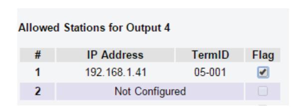
Check the Flag box beside each master station that will be "allowed" to trigger this relay for door release. Once all master stations have been checked, click Apply Settings at the bottom of this window to save the settings to memory. Reboot to update adaptor settings.
Note: The IS-SOFT software master stations can NOT be enabled for door release using the RY-IP44.
Input Programming
The RY‑IP44 adaptor has 4 inputs that can be programmed to trigger a call-in from a specific door station to a specific master station or group of master stations (max. 20). The RY‑IP44 inputs can have different calling rules than the default calling rule set under Advanced Station Settings in the IS Host Programming.
Choose the Call-In priority level for each input using the Priority drop down menu. Enter the target IP address of the door station for remote call-in.
Click Apply Settings to save the changes. Do not reboot the adaptor at this time. Click APPLICATION SETUP to return to the Application Configuration screen.
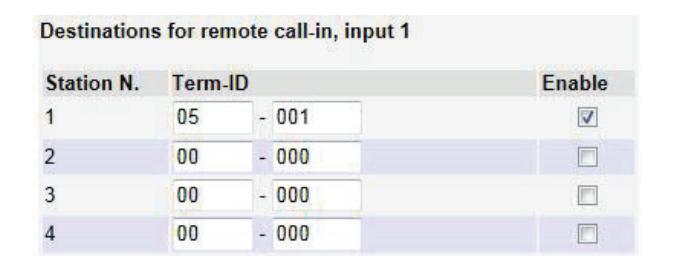
- Click on Destinations next to the input being configured. A new window will open.
- Enter the TermID for each master station to be called (see page 8 for TermID information). A maximum of 20 master station TermID's can be entered.
- Check the Enable box beside each TermID entered to allow the master to be called.
- Once all master station TermID's have been entered and enabled, click Apply Settings at the bottom of this window to save the settings to memory. Reboot to update adaptor settings.
RY-IP44 Dimensions
Depth: 1-1/4"
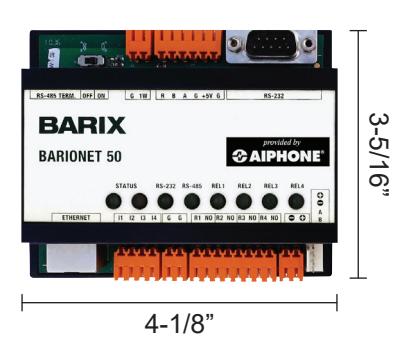
Mounting:
The RY-IP44 adaptor mounts to an Aiphone W-DIN11 mounting rail (sold separately).
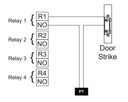
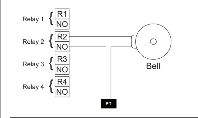
RY-IP44 Wiring
= Power Transformer (use proper power for the strike, mag lock, or external signaling device being used).
Relay contact rating: 30V DC, 0.5A.
Door release:
External signaling:
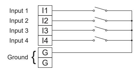
Inputs:
Connect a normally open (N/O) contact across any input and ground.
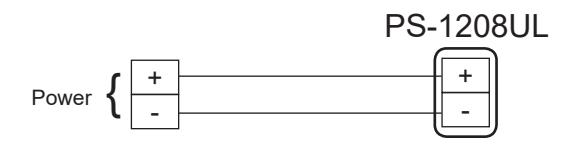
Power:
Use a 9-30V DC (300mA @ 12VDC) power supply to power the RY-IP44 adaptor. Use the Aiphone PS-1208UL power supply (sold separately).
FCC WARNING:
This device complies with Part 15 of the FCC rules.
Operation is subject to the following two conditions:
- (1) This device may not cause harmful interference.
- (2) This device must accept any interference that may cause undesired operation.
- For proper regulatory compliance, the drain wire should be disconnected at the power supply end of the cable.
- Changes or modifications not expressly approved by the party responsible for compliance could void the user's authority to operate the equipment.