Aiphone RY-IP44 with IPW1A Programming Manual Installation Instructions
Open the original PDF document
View PDF

RY-IP44
Input/Output Network Adaptor
Programming Manual For use with the IPW-1A
ATTENTION:
This manual is for programming the RY-IP44 with the IPW-1A only. Refer to the IPW-1A Installation and Operation Manuals for complete installation/programming information.
For instructions featuring the RY-IP44 with the IX2 Series, visit www.aiphone.com/IX2-RYIP44 For instructions featuring the RY-IP44 with the IS IP Series, visit www.aiphone.com/ISIP-RYIP44
Package Contents
- RY-IP44
- Programming Manual
- 6 Screw Terminal Blocks
- MAC Address Label
Installation Requirements
- General understanding of IPW-1A programming
- 9-30V DC power supply (sold separately)
- Unique IP address for each adaptor
Overview / Description
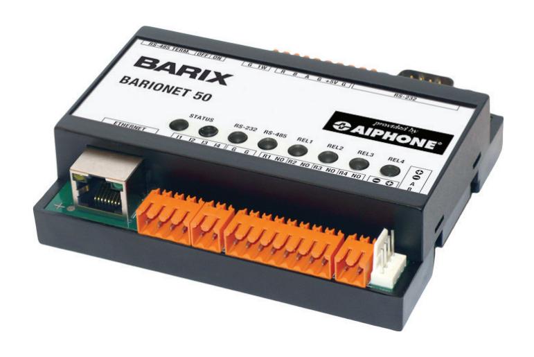
The RY-IP44 is a Barix Barionet 50 with proprietary firmware installed for the device to function with the Aiphone IPW-1A system.
The 4 relay outputs can be programmed to trigger for door release, while calling, while communicating, or while calling and communicating.
The RY-IP44 is not a PoE device and requires a dedicated 9-30V DC power supply. Use the Aiphone PS-1208UL power supply (sold separately).
Configuring the RY-IP44 (assigning IP address and system use)
The RY-IP44 has a default IP address of 192.168.1.45. Open a web browser and point the address bar to 192.168.1.45 for access to the adaptor. The first screen to appear will be the Device Status screen.
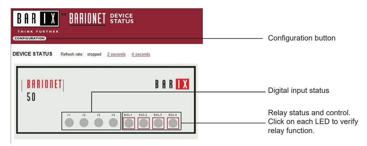
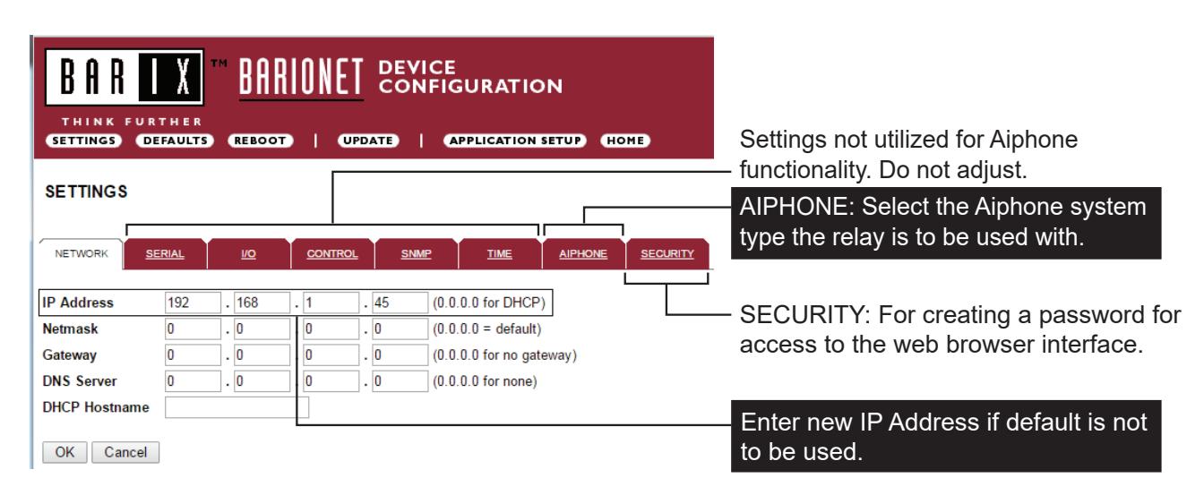
Click the CONFIGURATION button to open the Device Configuration screen. This is where a unique IP Address , Netmask , and Gateway can be assigned to the adaptor. Consult with your IT department for these settings.
Configuring the RY-IP44 (continued)
The Aiphone system type that the adaptor is being integrated with will need to be selected. Click the AIPHONE tab. Use the drop down by System Type to select the IPW-1A system. Enter a UDP Protocol Port number or leave at 0 to use the default (1724). When done, click OK. Click Reboot on the next screen to restart the adaptor.
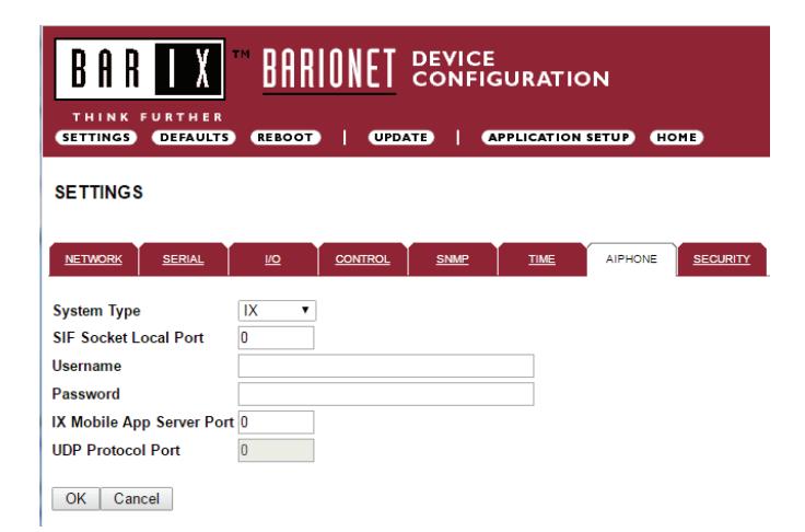
System Type : Select IPW-1A
UDP Protocol Port : Enter "0" if default port (1724) is to be used. Port 1724 is the default port on the IPW-1A stations for UDP messaging.
Relay Output Programming
The RY-IP44 has 4 relays that can be programmed to trigger while calling, while in communication, or while calling and communicating with a specific door station. The relays can also be programmed for door release.
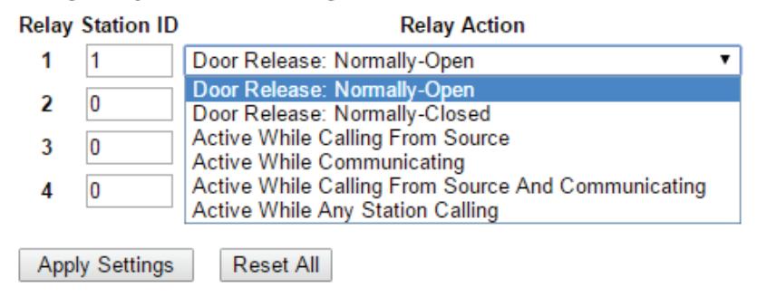
Relay Action options:
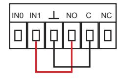
- Door Release Normally-Open • Door Release - Normally-Closed } *Relay will trigger when the PC master station pushes the door release button.
- Active while Calling from source
- Active while in Communication with source } Relay will trigger when the associated door station calls or communicates.
- Active during Calling and Communication
-
Active While Any Station Calling } Relay triggers when any station calls. No assignment required.
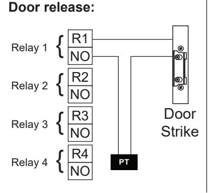
- * When using the RY-IP44 for door release, the relay on the IPW-1A must be set to door release and the relay must be jumpered to the sensor input as shown below.
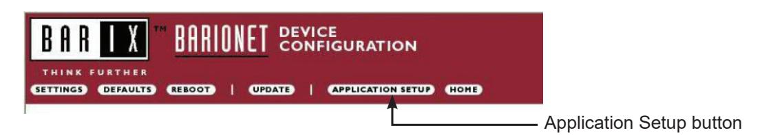
From the Device Configuration screen, click APPLICATION SETUP .
Relay Output Programming (continued)
Enter the Station ID for the IPW-1A to be associated with each relay on the RY-IP44. Select the relay condition from the Relay Action drop down menu. When done, click on Apply Settings . Click Reboot on the next screen to restart the adaptor with the applied settings.
Relay Output Functionality
RY-IP44 Dimensions

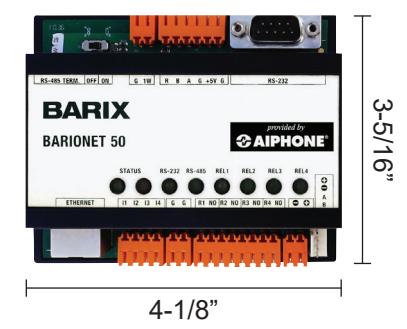
Mounting:
The RY-IP44 adaptor mounts to an Aiphone W-DIN11 mounting rail (sold separately).
RY-IP44 Wiring
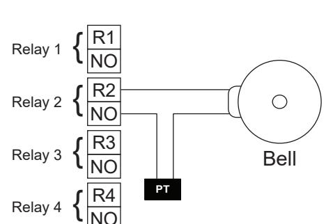
PT = Power Transformer (use proper power for the strike, mag lock, or external signaling device being used). Relay contact rating: 30V DC, 0.5A.
External signaling:
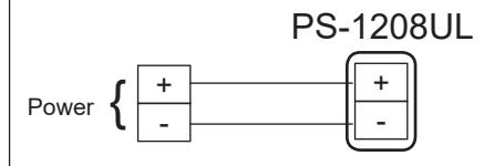
Power:
Use a 9-30V DC (300mA @ 12VDC) power supply to power the RY-IP44 adaptor. Use the Aiphone PS-1208UL power supply (sold separately).
FCC WARNING:
This device complies with Part 15 of the FCC rules.
Operation is subject to the following two conditions:
- (1) This device may not cause harmful interference.
- (2) This device must accept any interference that may cause undesired operation.
- For proper regulatory compliance, the drain wire should be disconnected at the power supply end of the cable.
- Changes or modifications not expressly approved by the party responsible for compliance could void the user's authority to operate the equipment.