Aiphone Paging Communicating System MC-604A Installation Instructions
Open the original PDF document
View PDF

MARKET-COM PAGING/COMMUNICATION SYSTEM
MC-60/4A MC-60/4B
INSTALLATION & OPERATION MANUAL
1 SYSTEM OUTLINE & COMPONENTS
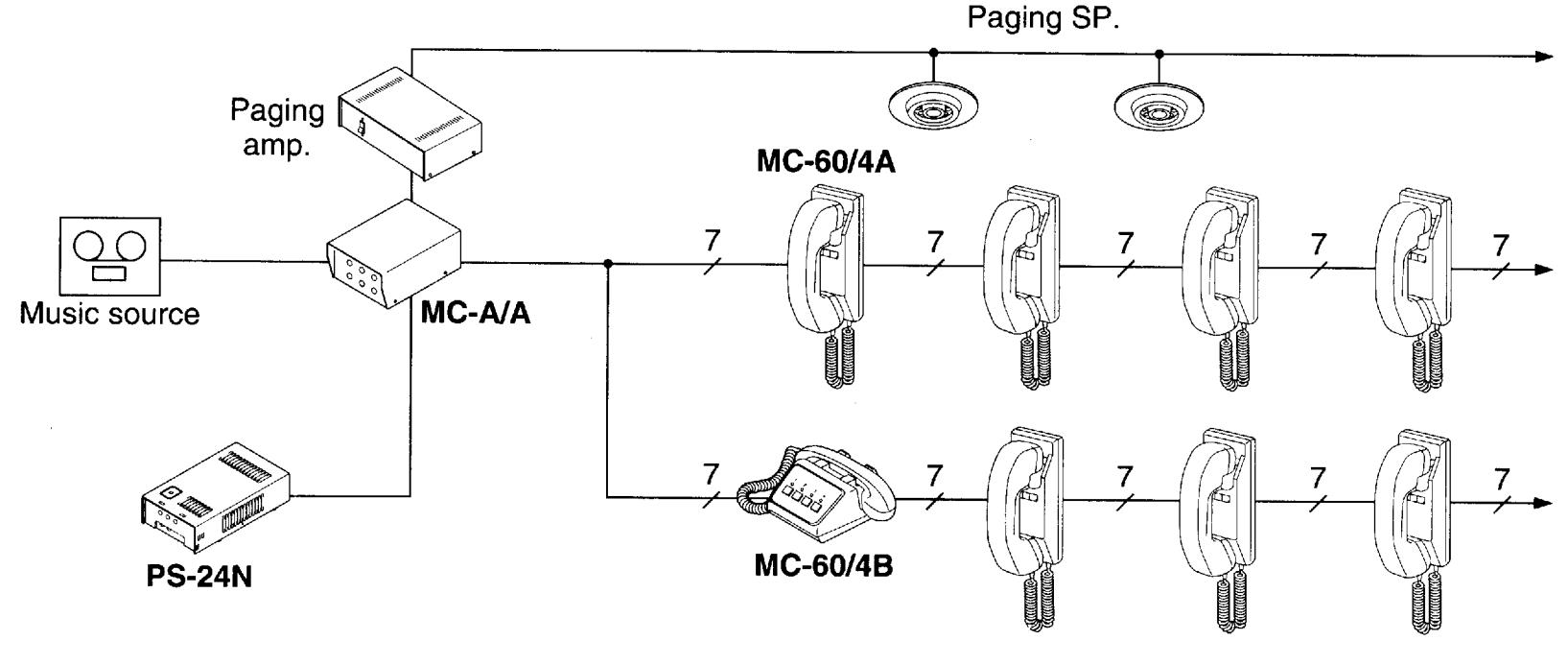
The MC-60/4 is a paging and communication system designed for retail stores, factories, and warehouses. The Market-Com locates individuals quickly through paging, and has two-way communication between any station in the system. The system is equipped with 4 communication channels, capacity of up to 60 stations, and incorporates paging and background music.
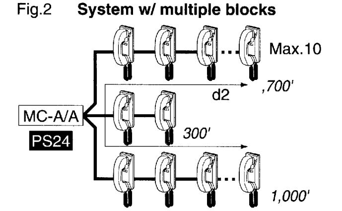
★MC-A/A holds max. 6 blocks of 10 MC-60/4A's.
Package contents
- Market-Com station (MC-60/4A or MC-60/4B)
- Package of screws
- Installation & Operation Manual
■ Components available
| MC-60/4A | MC-60/4B | MC-A/A | PS-24N |
|---|---|---|---|
| Wall-mount | Desk use | Market-com adaptor | Power supply |
• For MC-60/4A;
MCS-12: 12" checkstand pedestal (US only) MCS-23: 23" checkstand pedestal (US only)
MC-S6: Desk stand for MC-60/4A (1 pce per MC-60/4A as required)
• For paging & music;
PG-20C: Paging amplifier, 20W, wall mount with built-in paging adaptor (US only) PG-50C: Paging amplifier, 50W, wall mount with built-in paging adaptor (US only) PG-100C: Paging amplifier, 100W, wall mount with built-in paging adaptor (US only)
SP-5N: Ceiling speaker, 70V, 4W (US only) SSB-2: Ceiling support bracket for SP-5N AH-16TN: Horn speaker, 70V, 16W (US only) AH-32TN: Horn speaker, 70V, 32W (US only)
2 NAMES & FEATURES -
MC-60/4A
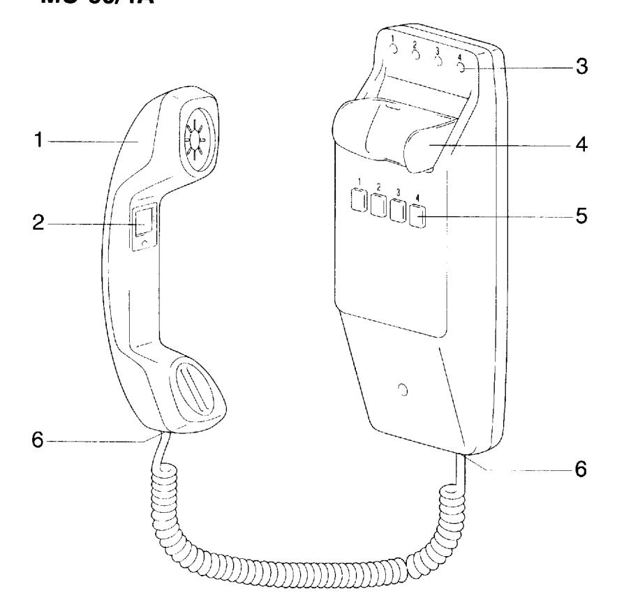
- 1 Handset
- 2 PAGE button
- 3 Channel occupied LED (4)
Ch.1 .....Red
Ch.2.....Green
Ch.3.....Yellow
Ch.4 .....Orange
- 4 Handset cradle
- 5 Channel selector button (4)
- 6 Jack (4 cond.)
MC-60/4B
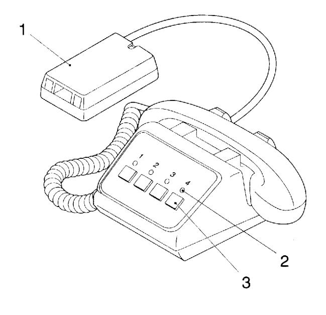
- 1 Terminal box w/1.5m, ,5' cord
- 2 Channel occupied LED (4)
Ch.1 .....Red
Ch.2.....Green
Ch.3.....Yellow
Ch.4.....Orange
3 Channel selector button (4)
■ Features
- Max. 60 stations per system
- 4 communication channels
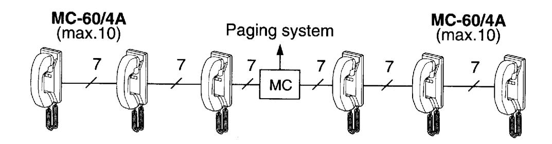
- Easy-to-run 7 conductor cable throughout the system, wired in blocks of up to 10 stations per block from adaptor/amplifier
- Illuminated LED indicates which channel is being used
- Conference calling for up to 3 stations
- Background music can be incorporated
- Automatic music muting during announcement
- Phone style coil cord with reinforced jacks (MC-60/4A)
- Durable handset cradle
3 PRECAUTIONS ON INSTALLATION & WIRING
- ★ Do not attempt to install or connect wires on MC-60/4 equipment while system's power supply is turned on.
- ★ MC-60/4 masters and related equipment are designed for indoor use only. Do not install outdoors.
- ★ Do not connect any other power source than specified on terminals 1/+ and 5/-. Doing so can damage the MC-60/4 equipment.
- ★ Do not open any MC-60/4 system components. Ask qualified personnel.
- ★ All the products of other manufacturers, power supply, buzzer, etc. used for MC-60/4 are not within our warranty, and must be used under manufacturer or distributor's specifications and warranty.
-
★ Do not mount MC-60/4 equipment in the following places, as it may cause the system to malfunction:
- High or extreme cold temperature areas: under direct sunlight, near equipment that varies in temperature, near an air-conditioner, inside refrigerating warehouse, etc.
- Places subject to moisture or humidity extremes.
- Places subject to environmental conditions, such as dust, oil and chemicals, etc.
- ★ MC-60/4 is an electrical appliance, which must not be subjected to water and or any other liquid.
-
★ Weather conditions, such as lightning storms, may cause damage to MC-60/4 equipment. It is suggested to take protective measures as follows;
- When a DC power supply is used: On the power supply with grounding terminal, be sure to take the terminal to earth ground. In this case, it is not necessary to connect a surge-arrester.
- If no grounding terminal is available, install the SA-1 surge arrester on the power supply line.
- Before MC-60/4 is actually installed, the contents of this Manual must be thoroughly read and understood.
4 WIRING
Actual Terminal Location
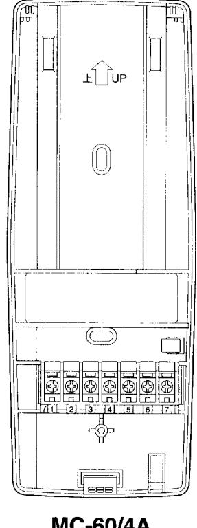
MC-60/4A Chassis inside view
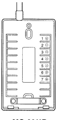
MC-60/4B Terminal box inside view
Connect all number terminals in parallel from station to station.
- 1 Power supply (+24V DC)
- 2 Paging signal
- 3 Talk channel 2
- 4 Talk channel 1
- 5 Power supply (–24V DC)★
- 6 Talk channel 3
- 7 Talk channel 4
- ★ When more than 7 conductor cable is used, connect extra wires on 5 terminal to avoid crosstalk.
■ Wiring diagram
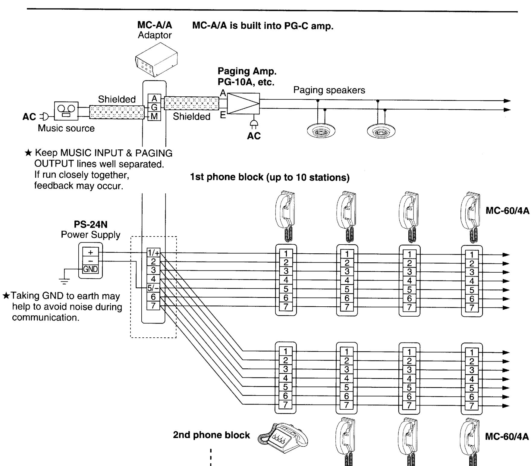
★When using PG-C Amplifiers ;
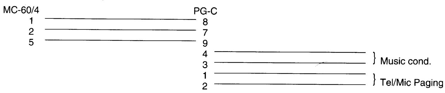
Up to 6 blocks
★Set dip switch 7 to ON position and switch 8 to OFF position.
MOUNTING
Mounting guidelines
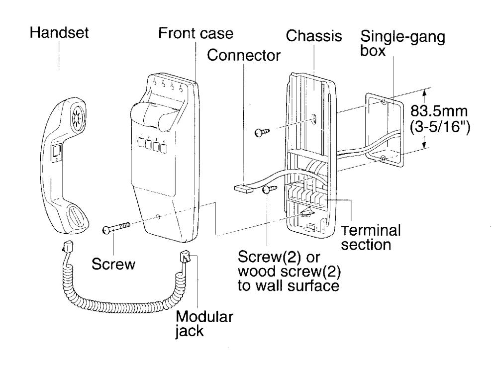
The MC-60/4A is designed for wall or pedestal mounting only.
- 1. Loosen screw on the bottom of the front case, and remove the unit by sliding the front case upward from the back chassis, then pull away. Disconnect the intercom from the back chassis by unplugging the multi-pin connector. Do not force the unit open. (Set the intercom unit aside while making wire terminations so as not to mar or scratch the unit.)
- 2. Install the back chassis to a single gang box or mounting ring, or directly to the wall.
- 3. All wiring terminations are done on the back chassis directly onto the screw terminal section. Designate a color code for wire numbers 1-7, and connect wires accordingly. Connect all like terminals together with matching wires.
- 4. Wiring is done in a daisy-chained method with up to 10 stations on a run.
- 5. When wiring is completed, reattach the intercom to the back chassis by plugging in the multi-pin connector. Align from the top and slide downward into position. Tighten screw at the bottom of the front case.
MC-60/4B
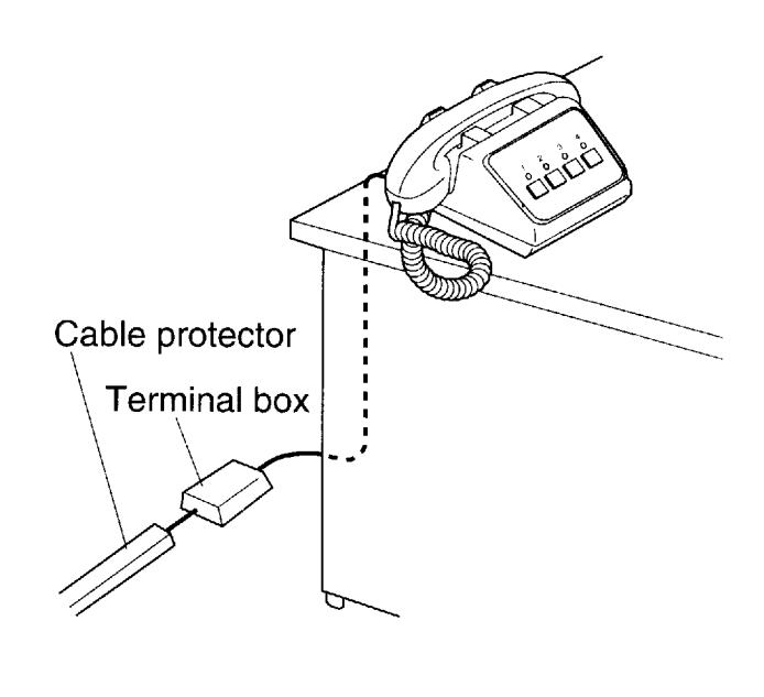
★ Install terminal box and cable in non-trapping manner.
6 OPERATIONS
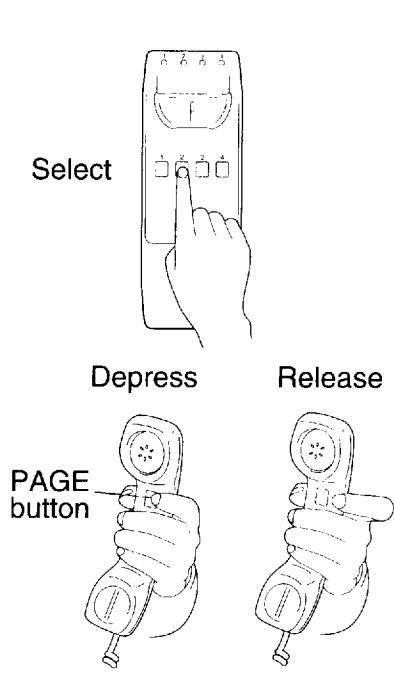
When an LED at the top of the station is lit, that channel is in use. Select another channel that is not in use. When any one station has a channel selected, the corresponding LED will be lit on all other stations. If responding to a call, select the station number that was requested by the person paging.
Calling
Select the channel number (1-4). Page & request a person to join in on a selected channel. Release
PAGE button and wait for reply.
When being paged
Go to the nearest MC-60/4 station, and select the channel you were requested on.
Conference calling
Call for up to 2 persons to a conference call on your selected channel. If more than 3 people join in,
communication volume may be affected.
• Music muting
When a station starts paging, pretone will sound and the music will be muted. When the page is completed.
the music will return.
★ Firmly depress channel number button in every operation.
7 TECHNICAL PRECAUTIONS
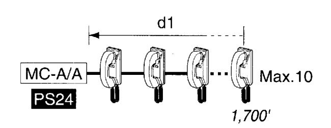
★ Make wiring blocks in a manner that wiring length of any two blocks added together does not exceed 1,700' w/ 22AWG either.
Fig.1 System w/ single block
- ★ The MC-60/4 is rated to operate at temperatures between 0°C ~ +40°C (32°F ~ 104°F).
- ★ Clean the MC-60/4 equipment with a soft cloth dampened with neutral household cleanser. Never use any abrasive cleaner or cloth.
8 SPECIFICATIONS
* Power source: DC24V. Use PS-24N power supply
* Consumption: Max. 70mA (in paging mode)
* Calling: By paging
* Communication: Enters each channel after pressing a channel selector button.
* Talk channel: 4 channels
* Station capacity: Max. 60 stations (in 6 blocks each with 10 MC-60/4 stations max. per block)
* Wiring: 7 conductors in loop (do not use twisted paired cable)
Use specified type No. 852207 (USA only), 420172 or line capacitance rating less than 25pF/feet.
* Dimensions: MC-60/4A: 9-1/4"H "W "D;
MC-60/4B : 4"H 8-7/8"W 7-1/2"D; 102H 225W 190D(mm)
* Weight: MC-60/4A: 1.06 lbs. (480g)(approx.). MC-60/4B: 2.65 lbs. (1.2kg)(approx.).
* Wiring distance:
Max. distance from MC-A/A to farthest MC-60/4 of a block (d1 in above Fig. 1)
| 24AWG | 22AWG | 18AWG | 0.5mm ∳ | 0.65mm ϕ | 1.0mm ϕ |
|---|---|---|---|---|---|
| 1,000' | 1,700' | 4,000' | 300m | 500m | 1,200m |
Also applies to farthest MC-60/4's of different blocks (d2 in above Fig.2)
★ Total wiring distance must not exceed 5,000'(1,500m) per system, regardless of wire size. Total wiring distance is the total length of all wiring blocks added together.
·i· ·i· ·i· ·i· ·i· ·i· ·i· ·i· ·i· ·i·
From MC-A/A to power supply PS-24N
| 18AWG | 0.5mm ϕ |
|---|---|
| 32' | 10m |
WARRANTY
Aiphone warrants its products to be free from defects of material and workmanship under normal use and service for a period of one year after delivery to the ultimate user and will repair free of charge or replace at no charge, should it become defective upon which examination shall disclose to be defective and under warranty. Aiphone reserves unto itself the sole right to make the final decision whether there is a defect in materials and/or workmanship; and whether or not the product is within the warranty.
This warranty shall not apply to any Aiphone product which has been subject to misuse, neglect, accident, or to use in violation of instructions furnished, nor extended to units which have been repaired or altered outside of the factory. This warranty does not cover batteries or damage caused by batteries used in connection with the product.
This warranty covers bench repairs only, and any repairs must be made at the shop or place designated in writing by Aiphone.
--------------------------------------
Aiphone will not be responsible for any costs incurred involving on site service calls.
COMMUNICATION SYSTEMS AIPHONE HOME, BUSINESS, INDUSTRY. Printed in Japan (E)