Aiphone NIM Series Operation Manual 2
Open the original PDF document
View PDFNIM system
OPERATION MANUAL
Thank you for selecting Aiphone for your communication needs.
* Please make sure to read this manual for safe and correct use of the system, and keep it in a safe place for future reference.
Please note that images and illustrations depicted in this manual may differ from the actual product.
Contents
|
Introduction
3 |
|---|
|
Precautions
3 |
|
WARNING
3 |
|
CAUTION
3 |
|
GENERAL PRECAUTIONS
3 |
|
NOTICES
3 |
|
GETTING STARTED
4 |
|
System confi guration
4 |
|
Part names
6 |
|
Master station
6 |
|
Sub station
7 |
|
Call button, wall jack
8 |
|
Corridor light, reset button
9 |
|
Software
10 |
| USING THE SYSTEM (AT THE |
| MASTER STATION)11 |
| Answering a call11 |
| When receiving a single call11 |
|
When receiving multiple calls
12 |
|
Calling sub stations
13 |
|
Calling a single sub station
13 |
|
Paging
14 |
|
Adjusting volume
15 |
| Adjusting receiving volume |
|
and ringtone volume
15 |
|
USING THE SYSTEM (AT A SUB
STATION) |
16 |
| Answering a call | 16 |
| Calling the master station | 16 |
| APPENDIX | 17 |
| Technical precautions | 17 |
| Troubleshooting | 17 |
| Specifi cations | 17 |
|
Warranty
Back cover |
Introduction
- The NIM system is a communication system designed for applications in facilities such as hospitals, offi ce buildings, factories, schools, and prisons. Various types of equipment enable you to confi gure a system that meets your needs for not only general purpose internal communications, but also for calling and communication in health care or various commercial applications. This system also allows you to check the call history by connecting a PC installed with the specifi ed application software.
- The NIM system is telecommunication equipment, not to be used as Medical Equipment.
Precautions
Prohibited Do not dismantle unit Keep unit away from water Be sure to follow the instruction
WARNING
Negligence could result in death or serious injury.
- 1. Do not dismantle or alter the unit. Fire or electric shock could result.
- 2. Keep the unit away from water or any other liquid. Fire or electric shock could result.
- 3. High voltage is present internally. Do not open the case. Electric shock could result.
- 4. For power supply, use Aiphone power supply model specifi ed for use with system. If non-specifi ed product is used, fi re or malfunction could result.
- 5. Do not connect any non-specifi ed power source to the +, terminals. Also, do not install two power supplies in parallel to a single input. Fire or damage to the unit could result.
- 6. Do not connect any terminal on the unit to an AC power line. Fire or electric shock could result.
- 7. Keep AC cord from being marred or crushed. If the AC cord is damaged, fi re or electric shock could result.
- 8. Do not plug or unplug unit with wet hands. Electric shock could result.
- 9. Periodically check for and remove dust on the power plug. If dust is left, it could cause the power plug to heat up, resulting in fi re.
- 10. Do not put any metal or fl ammable material into the unit through the openings. Fire, electric shock, or unit trouble could result.
CAUTION
Negligence could result in injury or damage to property.
- 1. Do not put anything on the unit or cover the unit with cloth, etc. Fire or unit trouble could result.
-
2. Do not install the unit in any of the following locations. Fire, electric shock, or unit trouble could result.
- * Places under direct sunlight or places near heating equipment that varies in temperature.
- * Places subject to dust, oil, chemicals, hydrogen sulfi de (hot spring).
- * Places subject to moisture and humidity extremes, such as bathrooms, cellars, greenhouses, etc.
- * Places where the temperature is quite low, such as inside a refrigerated area or in front of an air conditioner.
- * Places subject to steam or smoke (near heating or cooking surfaces).
- * Where noise generating devices such as dimmer switches or inverter electrical appliances are close by.
- * Locations subject to frequent vibration or impact.
- * Locations subject to extremely powerful electric fi elds.
GENERAL PRECAUTIONS
- 1. The unit is inoperative during power failure.
- 2. In areas where broadcasting station antennas are close by, this system may be affected by radio frequency interference.
- 3. Keep the intercom wires more than 30cm (12'') away from AC 100-240V wiring. AC induced noise and/or unit malfunction could result.
- 4. Do not connect any devices other than the Aiphone Models covered in this Manual.
- 5. All the units, except for Sub station, fl ush mount (NI-JA), are designed for indoor use only. Do not use at outdoor locations.
- 6. Using a mobile phone or professional-use radio equipment such as walkie-talkie close to the system may cause a malfunction.
- 7. If there are loud noises around the unit (such as music playing or children crying), the sound may break up and be diffi cult to hear.
NOTICES
- We will under no conditions be liable for damage that occurs due to the inability to communicate due to malfunctions, problems, or operational errors in this product.
- We will under no conditions be liable for any damages or losses resulting from this product's contents or specifi cations.
- This manual was created by Aiphone Co., Ltd., all rights reserved. Copying a part of or this entire manual without prior permission from Aiphone Co., Ltd. is strictly forbidden.
- Please note that images and illustrations depicted in this manual may differ from the actual ones.
- Please note that this manual may be revised or changed without prior notice.
- Please note that product specifi cations may be changed for the sake of improvement without prior notice.
- This system is not intended for life support or crime prevention. It is just a supplementary means of conveying information. Aiphone will under no conditions be liable for loss of life or property which occurs while the system is being operated.
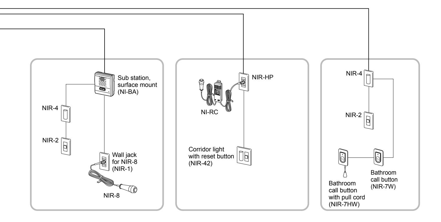
System configuration
The following is <u>a system configuration example</u>. You can select needed equipment to configure a system to meet your application needs.
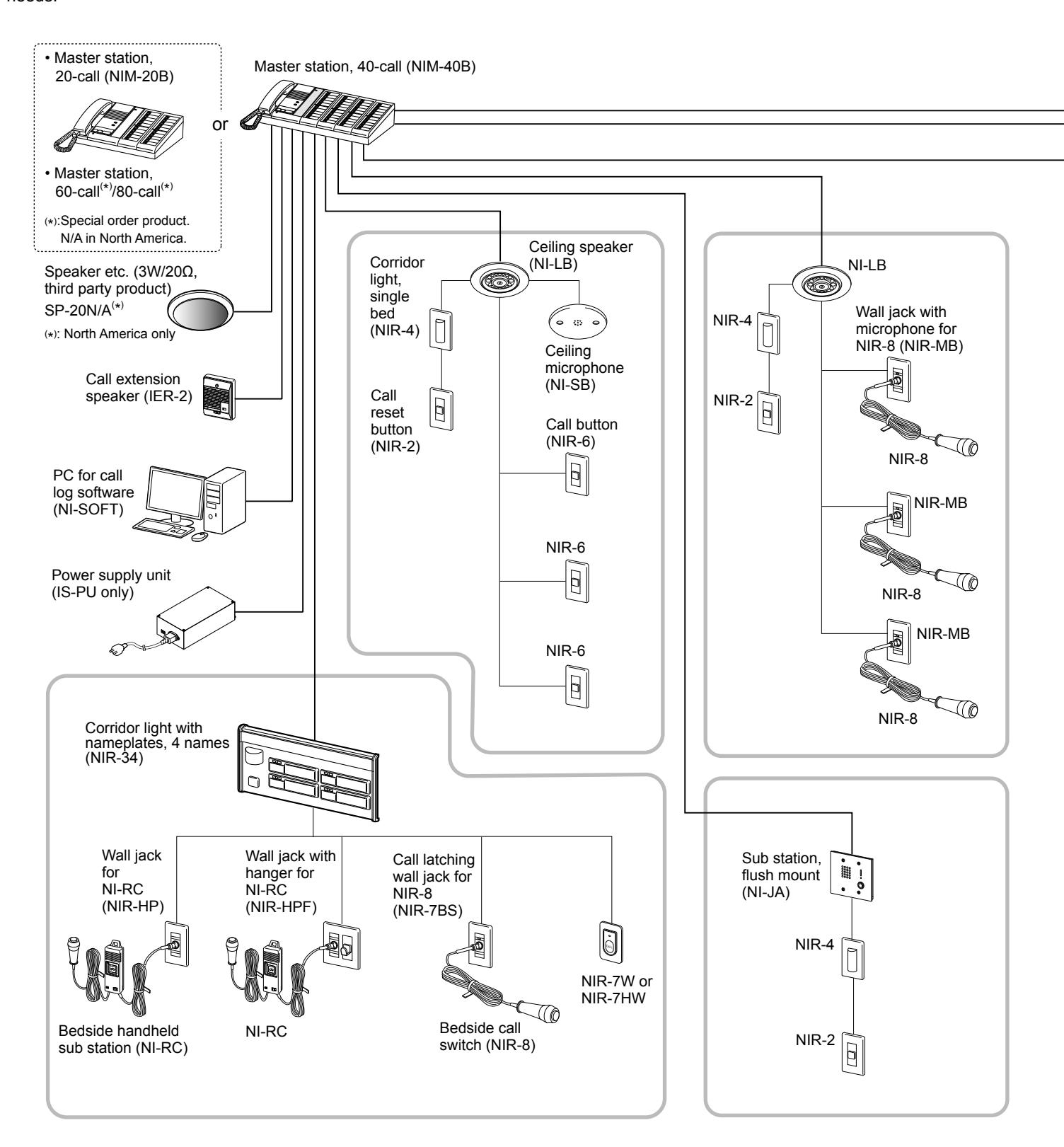
NOTE: The above example may differ from actual product.
■ Maximum number of stations in a single system
The maximum number of sub stations differs depending on the master station model.
| Master station | Developed commutes (Otro) | ||
|---|---|---|---|
| Model | Qty | Sub station (Qty) | Personal computer (Qty) |
| NIM-20B | 1 | 20 | 1 |
| NIM-40B | 1 | 40 | 1 |
| Master station, 60-call (*) | 1 | 60 | 1 |
| Master station, 80-call (*) | 1 | 80 | 1 |
(*): Special order product.
N/A in North America.
■ Communication methods
The following two methods are available on the master station.
| Method | Communication style | Description |
|---|---|---|
| Using handset | Voice-actuated communication | The communication mode is VOX, half duplex. When speaking into the handset, voice is transmitted to the other station. When listening, the voice from the remote station is heard through the handset. |
| Hands-free | Push-to-Talk | To speak, press and hold the TALK button. To listen, release the TALK button. |
Part names
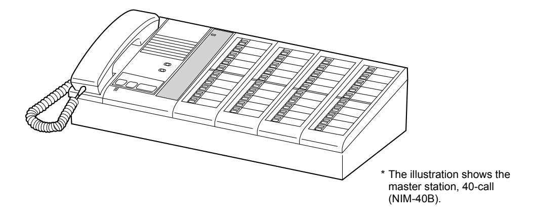
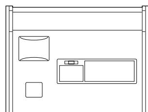
Master station
The following master station models are available.
| Model | Description | Model | Description |
|---|---|---|---|
| NIM-20B | Supports up to 20 sub stations. | Master station, 60-call (*) | Supports up to 60 sub stations. |
| NIM-40B | Supports up to 40 sub stations. | Master station, 80-call (*) | Supports up to 80 sub stations. |
(*): Special order product. N/A in North America.
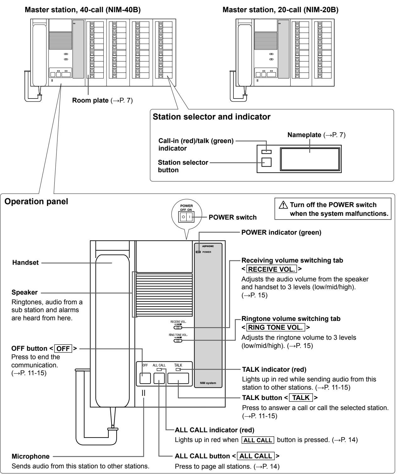
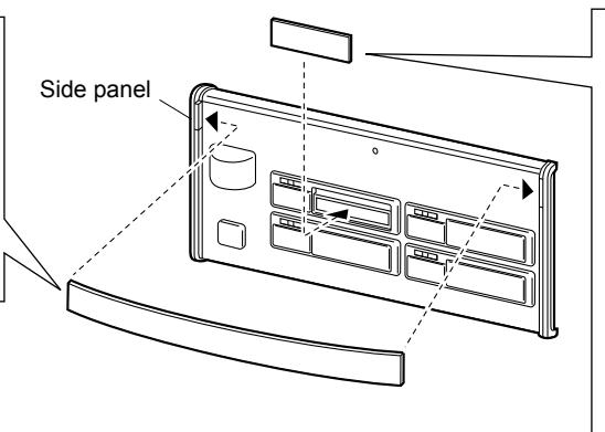
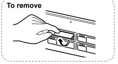
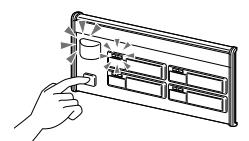
■ How to use the magnetic room and name plates
Room plate (included)
- Write information (e.g. room 1 number) on the plate in the corresponding positions.
- Attach the plate on the 2 corresponding position.
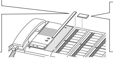
Nameplate (included)
- Write information (e.g. name) on 1 the plate.
- Attach the plate on the 2 corresponding position.
NOTES:
- Use an oil-based pen (a grease marker) to fi ll in the plate.
- When rewriting, be sure to remove the plate from the panel fi rst, and then wipe away the current contents with a soft cloth dampened with rubbing alcohol. Do not use thinner.
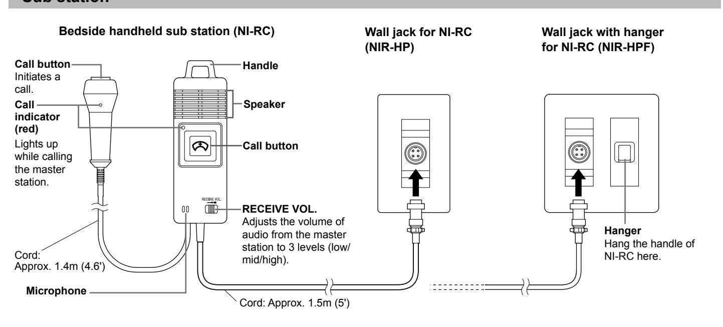
Sub station
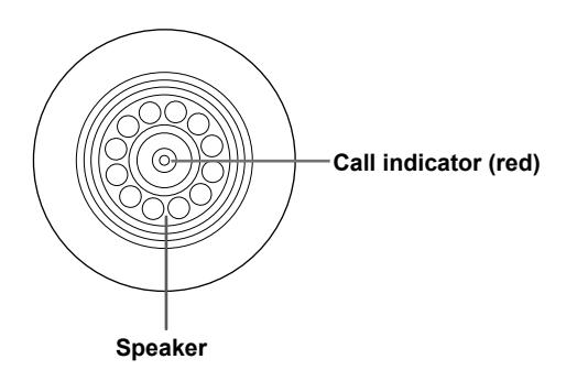
Ceiling speaker (NI-LB) Ceiling microphone (NI-SB)
Sub station, fl ush mount (NI-JA) Sub station, surface mount (NI-BA)
Call button, wall jack
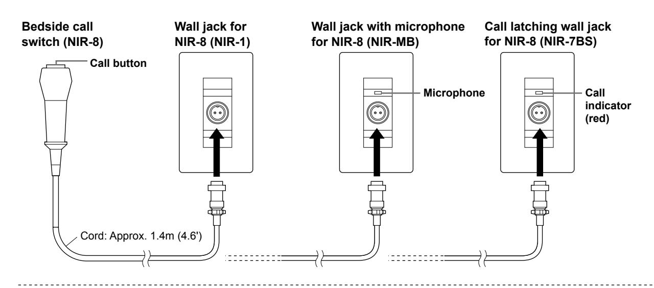
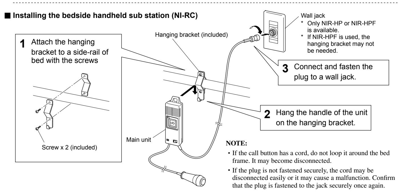
■ Connecting the bedside call switch (NIR-8)
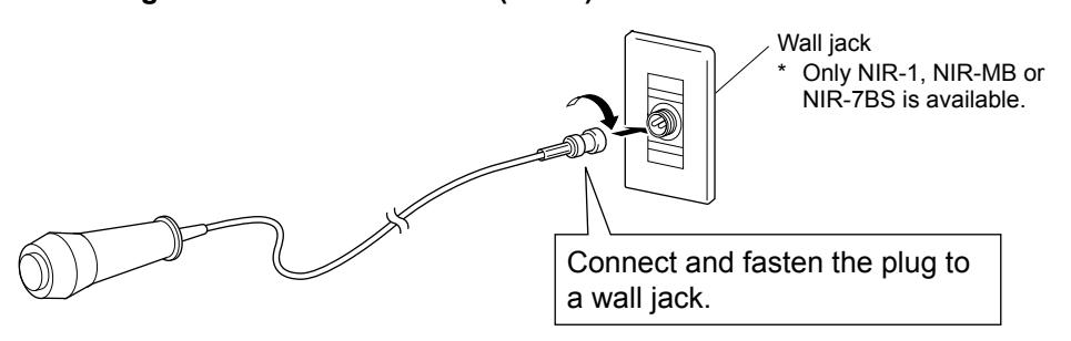
- If the call button has a cord, do not loop it around the bed frame. It may become disconnected.
- If the plug is not fastened securely, the cord may be disconnected easily or it may cause a malfunction. Confi rm that the plug is fastened to the jack securely once again.
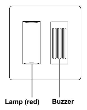
Corridor light, reset button

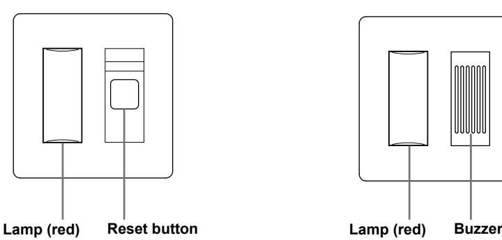
Corridor light with buzzer (NIR-4BZ)
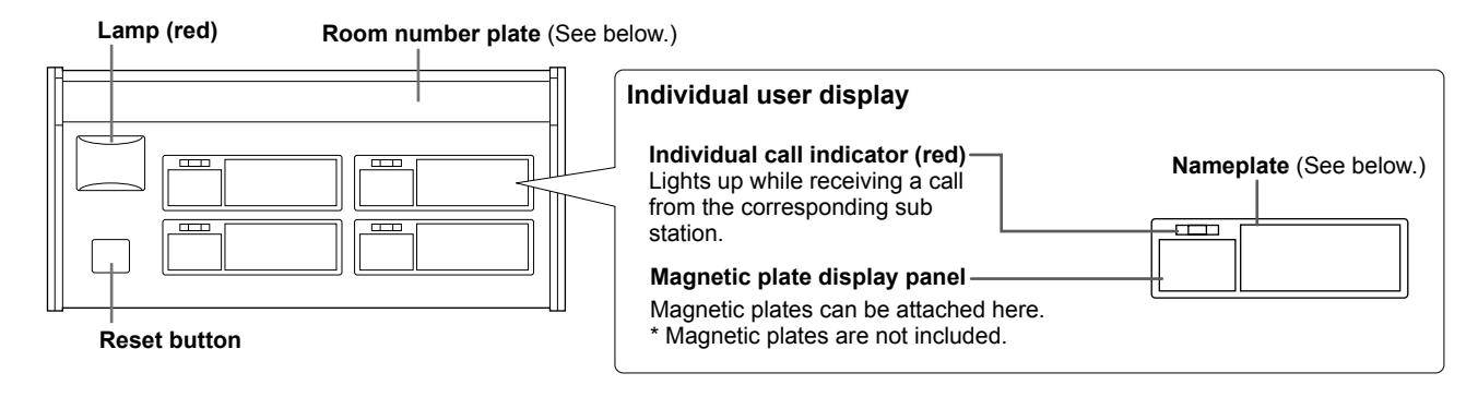
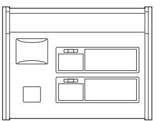
Corridor light with nameplates, 4 names (NIR-34)
Corridor light with nameplates, 2 names (NIR-32) Corridor light with nameplate, 1 name (NIR-31)
■ How to use the room number plate and magnetic nameplates
Room number plate (included)
- Write the room number on the 1 plate.
- Attach the plate to the corridor 2 light by putting both ends of the plate into the side panels of the corridor light.
Nameplate (included)
- Write the name of station, 1 user, etc. on the plate.
- Attach the plate to the 2 corresponding position.
NOTES:
- Use an oil-based pen (a grease marker) to fi ll in a plate.
- When rewriting, be sure to remove the plate from the panel fi rst, and then wipe away the current contents with a soft cloth dampened with rubbing alcohol. Do not use thinner etc.
Software
CD-ROM (NI-SOFT)
Call history management software.
RS232C cable
Connects the PC installed with the NI-SOFT to the master station.

* When extending the RS232C cable, the distance between the master station and the PC should be 15m (50') or less.
USING THE SYSTEM (AT THE MASTER STATION)
Answering a call
When receiving a single call
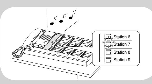
The following operations can be performed.
- The ringtone sounds.
- The call-in/talk indicator for the calling station blinks red.
- If a corridor light is installed at the sub station, it also lights up.
- If the call extension speaker IER-2 is installed, it sounds the same ringtone as the master station.
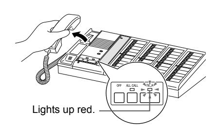
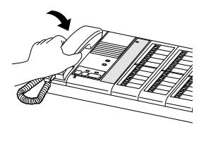
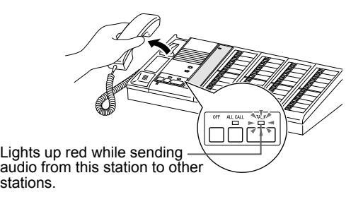
■ Answering with handset
Pick up the handset and talk 1 with the caller.
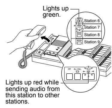
- * Corridor light and indicators on the equipment other than the master station turn off at the start of talking.
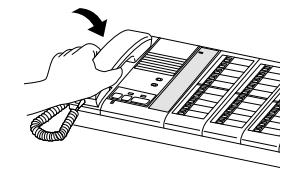
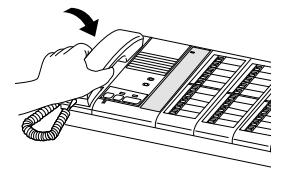
- To end the communication, 2 hang up the handset.
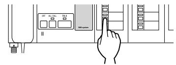
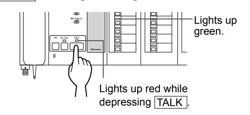
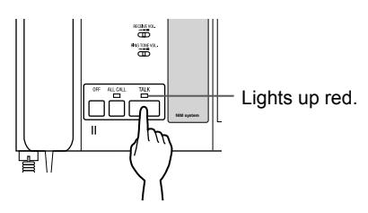
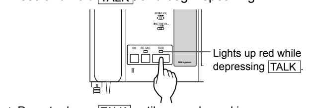
■ Answering in Push-to-Talk mode
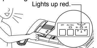
1 Press TALK and begin talking with the caller.
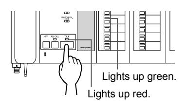
To speak
Press and hold TALK while speaking.
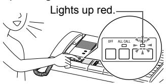
To listen to the caller Release TALK while listening.
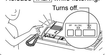
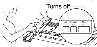
- * Corridor light and indicators on the equipment other than the master station turns off at the start of talking.
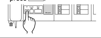
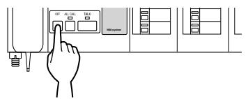
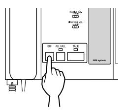
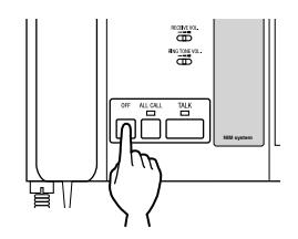
- To end the communication, 2 press OFF .
■ Going to the calling location directly
Go to the calling location and 1 press the reset button for the calling station.
The call indicator on the calling station and the corresponding indicators on the master station turn off.
* When two or more call indicators are lit on a corridor light, pressing the reset button turns off all the indicators.
- Communication will end automatically after 90 seconds.
- Confi rm the calling station before pressing the reset button. The indicators on the master station and corridor light will turn off when the reset button is pressed.
- Pressing OFF while talking ends the communication and turns off the indicators. Be sure to confi rm the calling station before pressing OFF .
- There is communication only if a sub station or speaker/microphone is installed in the calling location.
- When a new call comes in during communication, the call-in/talk indicator for the corresponding station blinks red and the ringtone sounds at a low volume.
- When you pick up the handset while communicating in Push-to-Talk mode, you can continue communicating by using the handset.
When receiving multiple calls
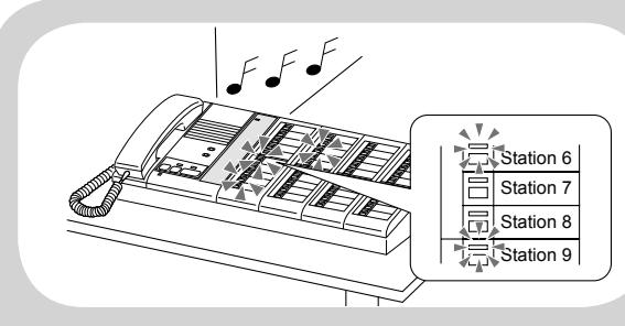
- The ringtone sounds.
- The call-in/talk indicators for the calling stations blink red.
- * Up to 10 calls are received on the master station at the same time. The 11th and subsequent calls are cancelled.
- * The call indicators on the stations of the 6th to 10th calls and the corresponding corridor lights do not light up.
- The corridor light installed at the sub station will light up during call-in.
- If the call extension speaker IER-2 is installed, it sounds the same ringtone as the master station.
The following operations can be performed.
■ Answering with handset
Press the selector button of 1 the calling station.
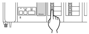
- * If the handset is picked up without selecting the calling station, the fi rst-come call is received.
- Pick up the handset and talk 2 with the caller.
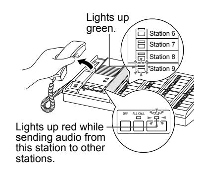
- * Corridor light and indicators on the equipment other than the master station turns off at the start of talking.
- To end the communication, 3 hang up the handset.
The call-in/talk indicator for the caller turns off.
- * To answer the next call, press OFF with the handset still off hook.
- * The ringtone sounds and the callin/talk indicators for other calls blink red. To answer another call, repeat step 1 - 3 .
■ Answering in Push-to-Talk mode
Press the station selector 1 button of the calling station.
- * If this step is skipped, the fi rstcome call is automatically selected.
- 2 Press TALK and begin talking with the caller.
To speak
Press and hold TALK while speaking.
To listen to the caller Release TALK while listening.
- * Corridor light and indicators on the equipment other than the master station turns off at the start of talking.
- To end communication, press 3 OFF .
The call-in/talk indicator for the caller turns off.
* The ringtone sounds and the callin/talk indicators for other calls blink red. To answer another call, repeat step 1 - 3 .
■ Going to the calling location directly
Go to the calling location and 1 press the reset button for the calling station.
The call indicator on the calling station and the corresponding indicators on the master station turn off.
* When two or more call indicators are lit on a corridor light, pressing the reset button turns off all the indicators.
- Communication will end automatically after 90 seconds.
- Confi rm the calling station before pressing the reset button. The indicators on the master station and corridor light will turn off when the reset button is pressed.
- Pressing OFF while talking ends the communication and turns off the indicators. Be sure to confi rm the calling station before pressing OFF .
- There is communication only if a sub station or speaker/microphone is installed in the calling location.
- When a new call comes in during communication, the call-in/talk indicator for the corresponding station blinks red and the ringtone sounds at a low volume.
- When you pick up the handset while communicating in Push-to-Talk mode, you can continue communicating by using the handset.
Calling sub stations
Calling a single sub station
Press the station selector button for the sub station to be called. 1
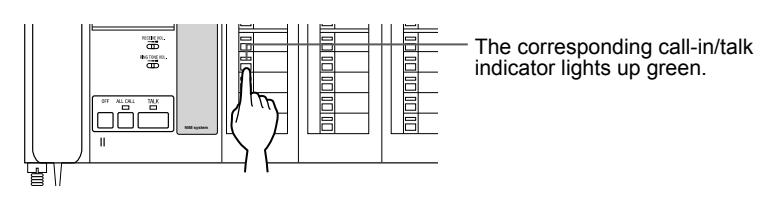
The following operations can be performed.
■ Talking with handset
Pick up the handset and talk with the user of the 2 sub station.
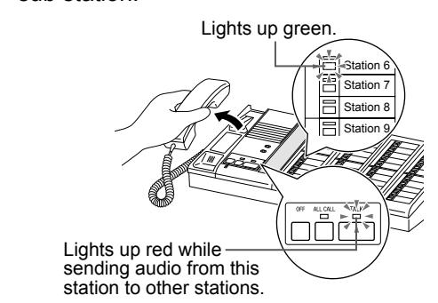
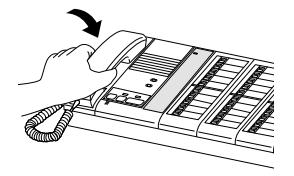
To end the communication, hang up the handset. 3
The call-in/talk indicator for the target sub station turns off.
■ Talking in Push-to-Talk mode
2 Press TALK and begin talking.
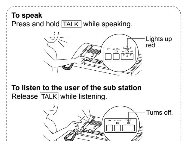
3 To end the communication, press OFF .
The call-in/talk indicator for the target sub station turns off.
- Communication will end automatically after 90 seconds.
- When a call comes in while you are talking with another station, you can answer it after ending the current communication.
- There is communication only if a sub station or speaker/microphone is installed in the calling location.
Paging
You can page all stations or only the selected stations simultaneously.
[When paging all stations]

■ Speaking with handset
Pick up the handset and begin speaking 2 .
A notice sound is heard at all the sub stations.
To end the paging, hang up the handset. 3
■ Speaking in Push-to-Talk mode
2 Press and hold TALK , and begin speaking.
* Do not release TALK until you end speaking.
A notice sound is heard at all the sub stations.
3 To end the paging, press OFF .
- Paging will end automatically after 90 seconds.
- When a call comes in while you are paging another station, you can answer it after ending the paging.
- Paging is possible only if a sub station or speaker/microphone is installed in the calling location.
- If a third party speaker is installed, it makes the same sound as the sub station.
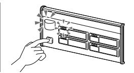
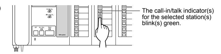
[When paging only the selected stations (Group Call)]
-
Press the station selector button(s)
1
for the sub station(s) to be called.
- * Up to 5 stations can be selected.

■ Speaking with handset
Pick up the handset and begin speaking 2 .
To end the paging, hang up the handset. 3
The call-in/talk indicators for the target sub stations turn off.
■ Speaking in Push-to-Talk mode
2 Press and hold TALK , and begin speaking.
- * Do not release TALK until you end speaking.
- 3 To end the paging, press OFF .
The call-in/talk indicators for the target sub stations turn off.
NOTES:
- Communication will end automatically after 90 seconds.
- When a call comes in while you are talking with another station, you can answer it after ending the current communication.
- There is communication only if a sub station or speaker/microphone is installed in the calling location.
- While speaking on the master station (the TALK indicator is lit), audio from the selected sub stations will not be heard at the master station.
- Audio from the selected sub stations will be heard simultaneously at the master station when the TALK indicator is turned off.
- Audio from each of the selected sub stations will be heard at the master station only.
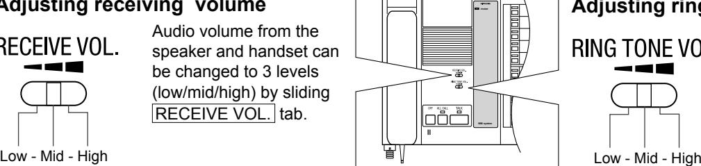
Adjusting volume
Adjusting receiving volume and ringtone volume
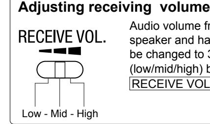
Audio volume from the speaker and handset can be changed to 3 levels (low/mid/high) by sliding RECEIVE VOL. tab.
Adjusting ring tone volume
The ringtone volume can be changed to 3 levels (low/mid/high) by sliding RING TONE VOL. tab.
USING THE SYSTEM (AT A SUB STATION)
Answering a call
When receiving a call from the master station;
A pretone is heard from the speaker, and the caller speaks.
* The type of speaker differs depending on the equipment used in your application.

Answer the caller by talking 1 .
Communication continues until the call is ended at the master station.
* Communication will end automatically after 90 seconds.
Calling the master station
Press the call button 1 .
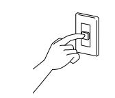
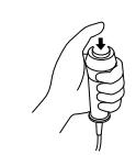
- * The type of call button differs depending on the equipment used in your application.
- When the master station answers, begin talking. 2
Communication continues until the call is ended at the master station.
* Communication will end automatically after 90 seconds.
- You cannot talk with the master station if no microphone/speaker is installed at your location.
- Talk into the microphone on the equipment.
- When calling the master station, confi rm that the call indicator on the equipment your are using is lit.
Technical precautions
Cleaning:
Clean all units with a soft cloth and gentle cleaner. Do not spray cleaner directly on unit. Do not use an abrasive cleaner or cloth.
Troubleshooting
If the system fails to operate normally, check the following points to determine whether the fault can be corrected by the simple measures suggested. If it cannot be corrected, or if the fault is not listed in the "Symptom" column, disconnect the power cord and contact the system supplier or service center for help.
| Symptom | Cause | Remedy |
|---|---|---|
|
The master station does
not operate. |
The power switch on the back of the master station is
in the OFF position. |
Turn on the power switch. (→ This manual,
page 6) |
| No ringtone |
Specifi cations
Master station, 20-call (NIM-20B) Master station, 40-call (NIM-40B) Master station, 60-call ( *) Master station, 80-call ( *)
| Power source |
48V DC (supplied from the power supply
unit) |
|
|---|---|---|
| Ambient temperature | 0 - 40°C (+32°F - +104°F) | |
| Communication | Handset: Voice-actuated communication | |
| VOX: Push-to-Talk (PTT) | ||
| Material |
Panel: Plastic
Chassis: SPCC |
|
| Color |
Panel: White
Chassis: Green mist |
|
| NIM-20B |
330 (W) x 230 (H) x 140 (D) mm
13" (W) x 9-1/16" (H) x 5-1/2" (D) |
|
| NIM-40B |
480 (W) x 230 (H) x 140 (D) mm
18-7/8" (W) x 9-1/16" (H) x 5-1/2" (D) |
|
| Dimensions |
*)
60-call( |
630 (W) x 230 (H) x 140 (D) mm
24-13/16" (W) x 9-1/16" (H) x 5-1/2" (D) |
|
80-call(
*) |
780 (W) x 230 (H) x 140 (D) mm
30-11/16" (W) x 9-1/16" (H) x 5-1/2" (D) |
|
| NIM-20B | Approx. 3.4 kg (7.48 lbs.) | |
| NIM-40B | Approx. 4.8 kg (10.56 lbs.) | |
| Weight |
60-call(
*) |
Approx. 6.4 kg (14.08 lbs.) |
|
*)
80-call( |
Approx. 7.8 kg (17.16 lbs.) |
( * ): Special order product. N/A in North America.
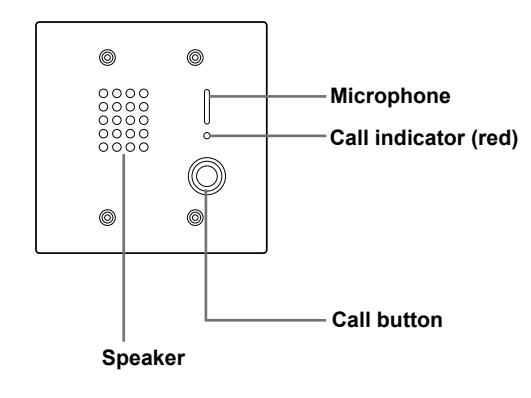
Sub station, surface mount (NI-BA)
| Power source | Supplied from the master station |
|---|---|
| Communication | Open voice hands-free communication |
| Ambient temperature | 0 - 40°C (+32°F - +104°F) |
| Mounting | Desktop use or wall (surface)-mount |
| Electrical box | 1-gang box |
| Material | Plastic |
| Color | White |
| Dimensions |
130 (W) x 150 (H) x 33 (D) mm
5-1/8" (W) x 5-7/8" (H) x 1-5/16" (D) |
| Weight | Approx. 290g (0.64 lbs.) |
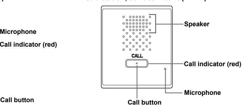
Sub station, fl ush mount (NI-JA)
| Supplied from the master station |
| Open voice hands-free communication |
| -10 - +60°C (+14°F - +140°F) |
| Flush-mount |
| 2-gang box |
|
Front panel: Stainless steel
Main unit: Plastic |
|
Front panel: Silver (stainless steel, vertical
hair-line processed) |
|
120 (W) x 120 (H) x 53.5 (D) mm
4-3/4" (W) x 4-3/4" (H) x 2-1/8" (D) |
| Approx. 380g (0.84 lbs.) |
| Protection class: IP54, IK07 |
Ceiling speaker (NI-LB)
| Power source | Supplied from the master station |
|---|---|
| Ambient temperature | 0 - 40°C (+32°F - +104°F) |
| Mounting | Flush-mount on the ceiling |
| Material | Plastic |
| Color | White |
| Dimensions |
ø180 x 62.5 (D) mm
ø7-1/16" x 2-7/16" (D) |
| Weight | Approx. 500g (1.1 lbs.) |
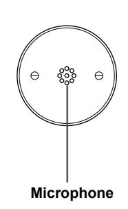
Ceiling microphone (NI-SB)
| Power source | Supplied from the master station |
|---|---|
| Ambient temperature | 0 - 40°C (+32°F - +104°F) |
| Mounting | Flush-mount on the ceiling |
| Applicable outlet box | Round shape with cover for depth of plastering |
| Material | Plate: Stainless steel |
| Dimensions |
ø105 x approx. 45 (D) mm
ø4-1/8" x approx. 1-3/4" (D) |
| Weight | Approx. 75g (0.17 lbs.) |
Bedside handheld sub station (NI-RC)
| Power source | Supplied from the master station |
|---|---|
| Communication | Open voice hands-free communication |
| Ambient temperature | 0 - 40°C (+32°F - +104°F) |
| Type | Handheld |
| Material | Plastic |
| Color | White |
| Dimensions |
56 (W) x 171.5 (H) x 28 (D) mm
2-3/16" (W) x 6-3/4" (H) x 1-1/8" (D) |
| Weight | Approx. 310g (0.68 lbs.) |
Wall jack for NI-RC (NIR-HP)
| Ambient temperature | 0 - 40°C (+32°F - +104°F) |
|---|---|
| Mounting | Wall (fl ush)-mount |
| Electrical box | 1-gang box |
| Material | Plastic |
| Color | White |
| Dimensions |
70 (W) x 120 (H) x approx. 37 (D) mm
2-3/4" (W) x 4-3/4" (H) x approx. 1-7/16" (D) |
| Weight | Approx. 90g (0.2 lbs.) |
Wall jack with hanger for NI-RC (NIR-HPF)
| Ambient temperature | 0 - 40°C (+32°F - +104°F) |
|---|---|
| Mounting | Wall (fl ush)-mount |
| Electrical box | 2-gang box |
| Material | Plastic |
| Color | White |
| Dimensions |
116 (W) x 120 (H) x approx. 53 (D) mm
4-9/16" (W) x 4-3/4" (H) x approx. 2-1/16" (D) |
| Weight | Approx. 140g (0.31 lbs.) |
Bedside call switch (NIR-8)
| Ambient temperature | 0 - 40°C (+32°F - +104°F) | |
|---|---|---|
| Material | Plastic | |
| Color | White | |
| Dimensions |
ø36 x 95 (H) mm
ø1-7/16" x 3-3/4" (H) |
|
| Weight | Approx. 90g (0.2 lbs.) | |
Wall jack for NIR-8 (NIR-1)
| Ambient temperature | 0 - 40°C (+32°F - +104°F) | |
|---|---|---|
| Mounting | Wall (fl ush)-mount | |
| Electrical box | 1-gang box | |
| Material | Plastic | |
| Color | White | |
| Dimensions |
70 (W) x 120 (H) x approx. 27 (D) mm
2-3/4" (W) x 4-3/4" (H) x approx. 1-1/16" (D) |
|
| Weight | Approx. 75g (0.17 lbs.) | |
Wall jack with microphone for NIR-8 (NIR-MB)
| Power source | Supplied from the master station | |
|---|---|---|
| Ambient temperature | 0 - 40°C (+32°F - +104°F) | |
| Mounting | Wall (fl ush)-mount | |
| Electrical box | 1-gang box | |
| Material | Plastic | |
| Color | White | |
| Dimensions |
70 (W) x 120 (H) x approx. 62 (D) mm
2-3/4" (W) x 4-3/4" (H) x approx. 2-7/16" (D) |
|
| Weight | Approx. 120g (0.26 lbs.) | |
Call latching wall jack for NIR-8 (NIR-7BS)
| Power source | Supplied from the master station | |
|---|---|---|
| Ambient temperature | 0 - 40°C (+32°F - +104°F) | |
| Mounting | Wall (fl ush)-mount | |
| Electrical box | 1-gang box | |
| Material | Plastic | |
| Color | White | |
| Dimensions |
70 (W) x 120 (H) x approx. 62 (D) mm
2-3/4" (W) x 4-3/4" (H) x approx. 2-7/16" (D) |
|
| Weight | Approx. 140g (0.31 lbs.) | |
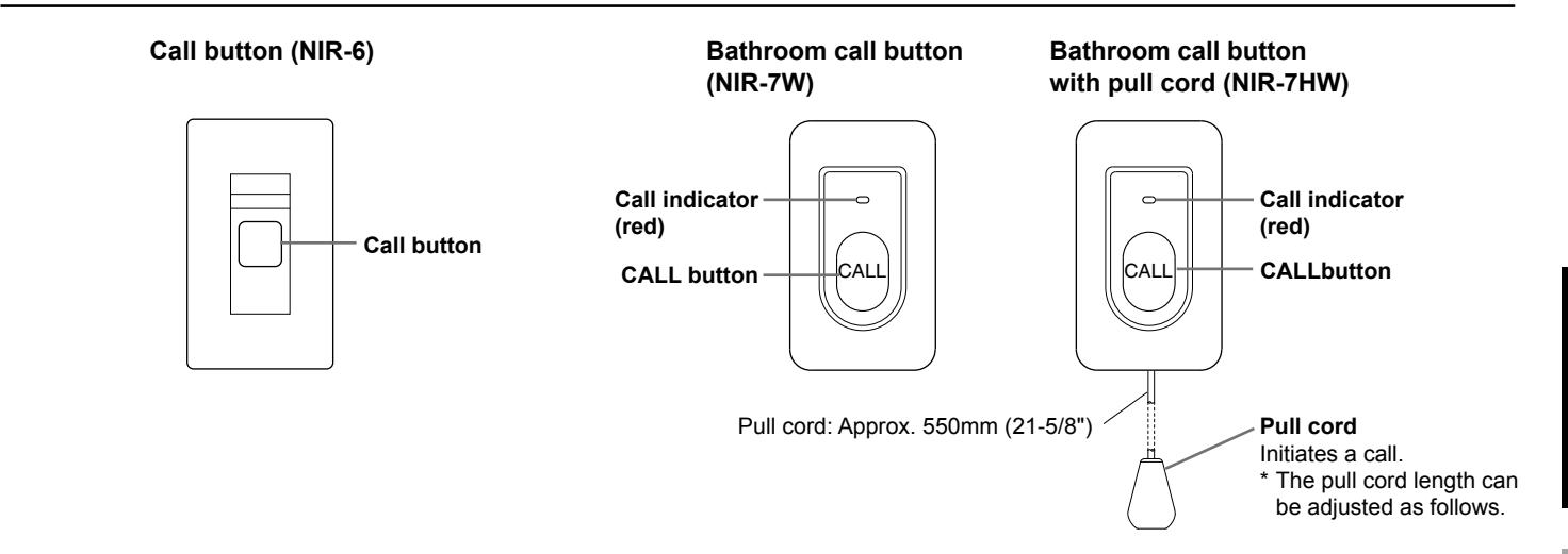
Call button (NIR-6)
| Ambient temperature | 0 - 40°C (+32°F - +104°F) | |
|---|---|---|
| Mounting | Wall (fl ush)-mount | |
| Electrical box | 1-gang box | |
| Material | Plastic | |
| Color | White | |
| Dimensions |
70 (W) x 120 (H) x approx. 38 (D) mm
2-3/4" (W) x 4-3/4" (H) x approx. 1-1/2" (D) |
|
| Weight | Approx. 85g (0.19 lbs.) | |
Bathroom call button (NIR-7W)
| Power source | Supplied from the master station | |
|---|---|---|
| Ambient temperature | 0 - 40°C (+32°F - +104°F) | |
| Mounting | Wall (fl ush)-mount | |
| Electrical box | 1-gang box | |
| Material | Plastic | |
| Color | White | |
| Dimensions |
70 (W) x 120 (H) x 25 (D) mm
2-3/4" (W) x 4-3/4" (H) x 1" (D) |
|
| Weight | Approx. 100g (0.22 lbs.) | |
| Remarks | Protection class: IPX4 | |
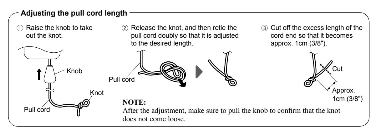
Bathroom call button with pull cord (NIR-7HW)
| Power source | Supplied from the master station | |
|---|---|---|
| Ambient temperature | 0 - 40°C (+32°F - +104°F) | |
| Mounting | Wall (fl ush)-mount | |
| Electrical box | 1-gang box | |
| Material | Plastic | |
| Color | White | |
| Dimensions |
70 (W) x 120 (H) x 25 (D) mm
2-3/4" (W) x 4-3/4" (H) x 1" (D) |
|
| Weight | Approx. 110g (0.24 lbs.) | |
| Remarks | Protection class: IPX4 | |
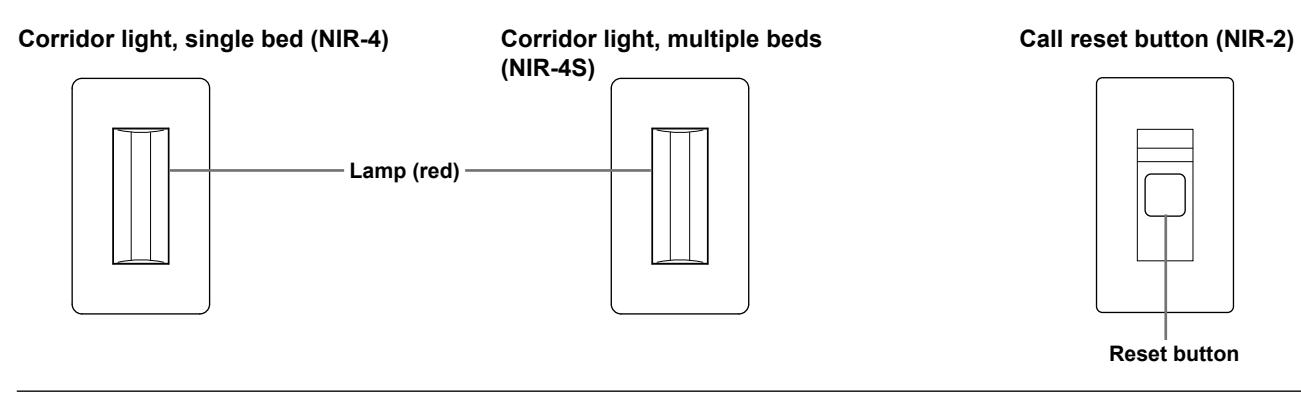
Corridor light, single bed (NIR-4) Corridor light, multiple beds (NIR-4S)
| Power source | Supplied from the master station | |
|---|---|---|
| Ambient temperature | 0 - 40°C (+32°F - +104°F) | |
| Mounting | Wall (fl ush)-mount | |
| Electrical box | 1-gang box | |
| Material | Plastic | |
| Color | White | |
| Dimensions |
70 (W) x 120 (H) x 28.5 (D) mm
2-3/4" (W) x 4-3/4" (H) x 1-1/8" (D) |
|
| Weight | Approx. 70g (0.15 lbs.) | |
Call reset button (NIR-2)
| Ambient temperature | 0 - 40°C (+32°F - +104°F) | ||
|---|---|---|---|
| Mounting | Wall (fl ush)-mount | ||
| Electrical box | 1-gang box | ||
| Material | Plastic | ||
| Color | White | ||
| Dimensions |
70 (W) x 120 (H) x approx. 38 (D) mm
2-3/4" (W) x 4-3/4" (H) x approx. 1-1/2" (D) |
||
| Weight | Approx. 85g (0.19 lbs.) | ||
Corridor light with reset button (NIR-42)
| Power source | Supplied from the master station | |
|---|---|---|
| Ambient temperature | 0 - 40°C (+32°F - +104°F) | |
| Mounting | Wall (fl ush)-mount | |
| Electrical box | 2-gang box | |
| Material | Plastic | |
| Color | White | |
| Dimensions |
116 (W) x 120 (H) x approx. 52 (D) mm
4-9/16" (W) x 4-3/4" (H) x approx. 2-1/16" (D) |
|
| Weight | Approx. 130g (0.29 lbs.) | |
Corridor light with buzzer (NIR-4BZ)
| Power source | Supplied from the master station | |
|---|---|---|
| Ambient temperature | 0 - 40°C (+32°F - +104°F) | |
| Mounting | Wall (fl ush)-mount | |
| Electrical box | 2-gang box | |
| Material | Plastic | |
| Color | White | |
| Dimensions |
116 (W) x 120 (H) x approx. 77 (D) mm
4-9/16" (W) x 4-3/4" (H) x approx. 3-1/16" (D) |
|
| Weight | Approx. 160g (0.35 lbs.) | |
Corridor light with nameplate 1 name (NIR-31) Corridor light with nameplate 2 name (NIR-32) Corridor light with nameplate 4 name (NIR-34)
| Power source | Supplied from the master station | |
|---|---|---|
| Ambient temperature | 0 - 40°C (+32°F - +104°F) | |
| Material | SPCC | |
| Color | White | |
| Dimensions | NIR-31 |
190 (W) x 144 (H) x 40 (D) mm
7-1/2" (W) x 5-11/16" (H) x 1-9/16" (D) |
| NIR-32 |
190 (W) x 144 (H) x 40 (D) mm
7-1/2" (W) x 5-11/16" (H) x 1-9/16" (D) |
|
| NIR-34 |
306 (W) x 144 (H) x 40 (D) mm
12-1/16" (W) x 5-11/16" (H) x 1-9/16" (D) |
|
| NIR-31 | Approx. 490g (1.08 lbs.) | |
| Weight | NIR-32 | Approx. 490g (1.08 lbs.) |
| NIR-34 | Approx. 810g (1.78 lbs.) | |
Warranty
Aiphone warrants its products to be free from defects of material and workmanship under normal use and service for a period of one year after delivery to the ultimate user and will repair free of charge or replace at no charge, should it become defective upon which examination shall disclose to be defective and under warranty. Aiphone reserves unto itself the sole right to make the fi nal decision whether there is a defect in materials and/or workmanship; and whether or not the product is within the warranty. This warranty shall not apply to any Aiphone product which has been subject to misuse, neglect, accident, power surge, or to use in violation of instructions furnished, nor extended to units which have been repaired or altered outside of the factory. This warranty does not cover batteries or damage caused by batteries used in connection with the unit. This warranty covers bench repairs only, and any repairs must be made at the shop or place designated in writing by Aiphone. This warranty is limited to the standard specifi cations listed in the operation manual. This warranty does not cover any supplementary function of a third party product that is added by users or suppliers. Please note that any damage or other issues caused by failure of function or interconnection with Aiphone products is also not covered by this warranty. Aiphone will not be responsible for any costs incurred involving on site service calls. Aiphone will not provide compensation for any loss or damage incurred by the breakdown or malfunction of its products during use, or for any consequent inconvenience or losses that may result.
The object area of is the EU.
FCC
This device complies with part 15 of the FCC Rules. Operation is subject to the following two conditions: (1) This device may not cause harmful interference, and (2) this device must accept any interference received, including interference that may cause undesired operation.
NOTE: This equipment has been tested and found to comply with the limits for a Class B digital device, pursuant to part 15 of the FCC Rules. These limits are designed to provide reasonable protection against harmful interference in a residential installation. This equipment generates, uses and can radiate radio frequency energy and, if not installed and used in accordance with the instructions, may cause harmful interference to radio communications. However, there is no guarantee that interference will not occur in a particular installation. If this equipment does cause harmful interference to radio or television reception, which can be determined by turning the equipment off and on, the user is encouraged to try to correct the interference by one or more of the following measures:
- Reorient or relocate the receiving antenna.
- Increase the separation between the equipment and receiver.
- Connect the equipment into an outlet on a circuit different from that to which the receiver is connected.
- Consult the dealer or an experienced radio/TV technician for help.
IC CAN ICES-3 (B)/NMB-3(B)

AIPHONE CO., LTD., NAGOYA, JAPAN Issue Date: Feb. 2016
FK2243 A P0216 SZ 57290