Aiphone Modular Tower Assembly Instructions
Open the original PDF document
View PDF

Modular Tower
Modular Tower Assembly Instructions
Ensure all of the components required to complete the installation are present.
TW-MKL L-Bracket Mounting Kit Contents:
- 4 x L-Bolts
- 8 x ¾" Hex Nuts
- 8 x ¾" Washers
- 1 x Printed Template
- 1 x Assembly Instructions
- It is recommended to transfer the provided template to a piece of wood between ½" and 1" thick. This will make it easier to properly position the L-bolts into the poured concrete foundation in Step 3.
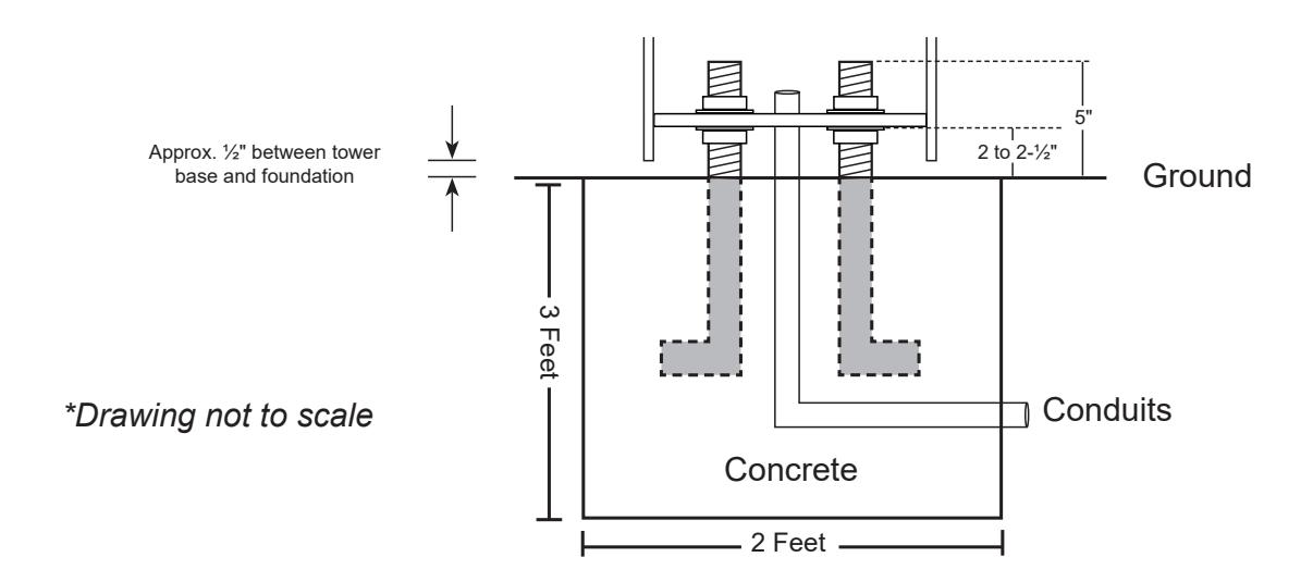
TW-MKL Installation:
- 1. Intercom and electrical wire conduits should be run through the foundation and into the center 4" diameter hole of the tower base module. These cable runs must be run separately, not in the same conduit. Note: It is the responsibility of the installer to ensure that all applicable electrical codes are met.
- 2. Pour the foundation at least 2 feet in diameter and 3 feet deep and in accordance with local building codes and frost line.
- 3. Install the 4 L-bolts below the grade with 5" projecting above the grade (see drawing below). Use the template to properly position the L-bolts within the concrete foundation.
- 4. Once the foundation has set, remove the template. Install one ¾" hex nut and one washer on each L-bolt 2 to 2-½" above grade to the top of the washer. This will allow for a ½" air gap between the foundation and tower base to allow airflow and prevent moisture problems. Verify that the nuts are level.
Modular Section Contents:
1 x Base Module w/ Access Panel
1 x Top Module w/ Access Panel
1 x Top Plate with or w/o Light Cage
6 x Access Panel Screws
6 x Access Panel Screws 1 x Module Securing Kit
2 x Plate Securing Screws
1 x *Middle Module w/ Access Panel
6 x Access Panel Screws
1 x CCTV Camera Arm Module
1 x Module Securing Kit 1 x Module Securing Kit
* Middle module includes an LED light for illuminating the intercom station.
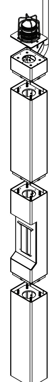
Tower Assembly:
Note: The tower assembly instructions that follow are for a 3-module tower with camera arm module and strobe light. Skip the steps that don't apply to your specific tower installation.
- 1. Remove the access panel from each tower module. Carefully install the base module onto the level washers/nuts, ensuring that the unit is oriented in the desired direction (access panel is on the back). Check that the tower base is level at this point. Install the second set of nuts and washers on the L-bolts and carefully tighten them, securing the tower base to the concrete foundation. Adjust as necessary.
- 2. Place the top module onto the middle module. Carefully align and secure the modules together using the provided securing bolts. Use the station or access panel opening in the middle module to thread in the securing bolts from below and fasten the modules together.
- 3. Place the middle and top modules onto the base module of the tower and carefully align them. (It is recommended to have two people lift the connected middle/top assembly into place). Use the provided securing bolts to fasten the modules together. Use the access panel opening in the base module to thread in the securing bolts from below.
- 4. To install the camera arm module, a ladder or some means of reaching the top of the tower will be needed. Use the ladder to carry the camera arm module to the top of the assembled tower. Use the access panel opening in the top module to thread in the securing bolts from below and fasten the camera arm module to the tower. Fish the required wire for the camera through the camera arm.
- 5. To install the top plate with light cage, feed the wires for the light through the hole on the top of the camera arm module. Fasten the top plate to the top of the camera arm module using the provided securing screws.
- The beacon/strobe will require a dedicated 24V DC power supply. This power supply can also be used to power the LED illuminator in the middle module.
- 6. Complete all intercom, camera, and power wiring connections. Secure the intercom to the middle module using the screws supplied with the station. As a final step, secure the access panels to each module of the tower using the provided panel screws.
Specifications:
Material: ¼" zinc-treated steel with powder coating Dimensions: Base Module: 34-¼" H x 10" W x 8" D
Middle and Upper Modules: 33" H x 10" W x 8" D Camera Arm Module: 67-⅞" H x 10" W x 12- 13 ⁄16 " D